IMV K2 User manual

Multi-Degree-Of-Freedom Sine Vibration Control System
K2
Multi-SINE
Instruction Manual
IMV CORPORATION

Type of document Instruction manual
System applied K2
Software <K2/Multi-SINE> later than Version 14.3.0

Japanese edition
Version Date Contents
6.0.0 2010.12.01 First edition
6.1.0 2011.09.26 Additional description of “Minimum value control”
10.0.0 2013.08.09 Renewal of screen display, modified description of test files and modified
description of input channels
13.0.0 2017.03.10 Additional description of the setting for skip of saving data files of auto-save at
each sweep turnover (or spot repeat), correction of misprints
13.5.0 2017.06.27 Additional description of XFR Measure by white noise
13.6.0 2017.10.02 Additional description of operation related to Live data in operation,
Correction of misprints
14.1.0 2018.04.27 Additional description of slope in interpolation type of control reference
profile
14.2.0 2018.09.10 Additional description of “type of interpolation” of control reference profile
14.3.0 2019.04.19 Modified description of Data save condition, correction of misprints
English edition
Version Date Contents
6.0.0 2010.12.01 First edition
6.1.0 2011.09.26 Additional description of “Minimum value control”
10.0.0 2013.08.09 Renewal of screen display, modified description of test files and modified
description of input channels
10.0.1 2016.07.29 Correction of misprints
13.0.0 2017.03.10 Additional description of the setting for skip of saving data files of auto-save at
each sweep turnover (or spot repeat), correction of misprints
13.5.0 2017.06.27 Additional description of XFR Measure by white noise
13.6.0 2017.10.02 Additional description of operation related to Live data in operation,
Correction of misprints
14.1.0 2018.04.27 Additional description of slope in interpolation type of control reference
profile
14.2.0 2018.09.10 Additional description of “type of interpolation” of control reference profile
14.3.0 2019.04.19 Modified description of Data save condition, correction of misprints


CONTENTS
Chapter 1 Outline of the System........................................................... 1-1
1.1 Specifications .................................................................... 1-1
1.1.1 Multi-SINE .................................................................. 1-1
1.1.2 Limit Control (Option of Multi-SINE) ........................................ 1-3
Chapter 2 Operation System of K2 Application.............................................. 2-1
2.1 Outline ........................................................................... 2-1
2.2 Test File ......................................................................... 2-2
2.3 Test Type ......................................................................... 2-2
Chapter 3 Basic Operation................................................................. 3-1
3.1 Sweep (Simplified definition) ..................................................... 3-1
3.2 Sweep (Detailed Definition Break Point)............................................ 3-23
3.3 Spot Test ......................................................................... 3-47
Chapter 4 Test Definition................................................................. 4-1
4.1 Outline ........................................................................... 4-1
4.2 Fundamental/Control Condition ..................................................... 4-2
4.2.1 Controlled variable ......................................................... 4-2
4.2.2 Max. Observation Frequency .................................................. 4-2
4.2.3 Peak amplitude estimation ................................................... 4-3
4.2.4 Loop check .................................................................. 4-4
4.2.5 Equalization mode ........................................................... 4-5
4.2.6 Shutdown time ............................................................... 4-6
4.3 Multi-axis/multi-point control condition........................................... 4-8
4.3.1 Frequency Resolution ........................................................ 4-8
4.3.2 Specify the time of XFR measurement excitation .............................. 4-8
4.3.3 Cross-talk control .......................................................... 4-9
4.3.4 Drive saving ................................................................ 4-9
4.3.5 Multi-axis/multi-point control speed ........................................ 4-12
4.4 Excitation group .................................................................. 4-14
4.4.1 Outline ..................................................................... 4-14
4.4.2 Excitation group configuration .............................................. 4-15
4.4.3 Excitation group information ................................................ 4-16
4.4.3.1 XFR loop check voltage ................................................ 4-16
4.4.3.2 XFR function measure voltage .......................................... 4-16
4.4.3.3 Initial output voltage ................................................ 4-17
4.4.3.4 Max. drive voltage .................................................... 4-17
4.4.3.5 Testing abort output voltage .......................................... 4-17
4.4.3.6 Operate initial loop check ............................................ 4-18
4.4.3.6.1 Frequency....................................................... 4-18

4.4.3.6.2 Output voltage ................................................. 4-18
4.4.3.6.3 Severity ....................................................... 4-18
4.4.3.6.4 Environment noise limit ........................................ 4-19
4.4.3.6.5 Response linearity check ....................................... 4-19
4.4.3.6.6 Response upper limit check ..................................... 4-19
4.5 Control reference ................................................................. 4-20
4.5.1 Sweep test .................................................................. 4-21
4.5.1.1 Sweep mode............................................................ 4-21
4.5.1.2 Direction............................................................. 4-22
4.5.1.3 Sweep rate............................................................ 4-23
4.5.1.4 Hold the sweep at the maximum sweep frequency ......................... 4-23
4.5.1.5 Sweep pause time...................................................... 4-24
4.5.1.6 Profile definition.................................................... 4-24
4.5.1.7 Tolerance definition.................................................. 4-24
4.5.1.8 Test time............................................................. 4-24
4.5.1.9 Zero Reference........................................................ 4-25
4.5.1.10 Relative Amplitude................................................... 4-25
4.5.1.11 Relative Phase....................................................... 4-26
4.5.2 Spot test................................................................... 4-27
4.5.2.1 Spot Reference definition............................................. 4-28
4.5.2.1.1 Frequency ...................................................... 4-29
4.5.2.1.2 Level .......................................................... 4-29
4.5.2.1.3 Abort / Alarm level ............................................ 4-29
4.5.2.1.4 Stay time ...................................................... 4-30
4.5.2.2 Auto-generation condition of the spot by profile ...................... 4-30
4.5.2.2.1 Generating mode ................................................ 4-31
4.5.2.2.2 Generation interval ............................................ 4-31
4.5.2.2.3 Direction ...................................................... 4-31
4.5.2.2.4 Stay time (By seconds) ......................................... 4-31
4.5.2.2.5 Stay time (By vibration cycles)................................. 4-32
4.5.2.2.6 Profile definition ............................................. 4-32
4.5.2.2.7 Tolerance definition ........................................... 4-32
4.5.2.3 Test time............................................................. 4-32
4.5.2.4 Repeat pause time..................................................... 4-33
4.5.2.5 Not stop the signal at shifting the spots when the condition is ready . 4-33
4.5.2.6 Manual operation initial parameters is to be changed .................. 4-33
4.5.2.7 Zero Reference........................................................ 4-34
4.5.2.8 Relative Amplitude.................................................... 4-34
4.5.2.9 Relative Phase........................................................ 4-34
4.5.3 Profile definition .......................................................... 4-35

4.5.3.1 Simplified definition ................................................. 4-36
4.5.3.2 Detailed definition (Constant) ........................................ 4-37
4.5.3.2.1 Break point / Frequency (Constant) .............................. 4-38
4.5.3.2.2 Break point / Level (Constant) .................................. 4-38
4.5.3.3 Detailed Definition (Interpolation) ................................... 4-39
4.5.3.3.1 Type of interpolation ........................................... 4-40
4.5.3.3.2 Unit of slope................................................... 4-40
4.5.3.3.3 Break Point / Frequency (Interpolation) ......................... 4-40
4.5.3.3.4 Break Point / Level (Interpolation) ............................. 4-40
4.5.3.3.5 Break Point / Slope (Interpolation) ............................. 4-41
4.5.3.4 Measured Profile Definition ........................................... 4-42
4.5.3.4.1 Outline......................................................... 4-42
4.5.3.4.2 Load the Data File.............................................. 4-43
4.5.3.4.3 Type of interpolation ........................................... 4-44
4.5.3.4.4 Data Processing................................................. 4-44
4.5.3.4.4.1 LPF (Low Pass Filter) Setting............................. 4-44
4.5.3.4.4.2 HPF (High Pass Filter) Setting............................ 4-45
4.5.3.4.4.3 Level Change.............................................. 4-45
4.5.3.4.5 CSV data file (Measured profile) ................................ 4-46
4.5.4 Tolerance definition ........................................................ 4-47
4.5.4.1 Tolerance ............................................................. 4-48
4.5.5 CALC Function ............................................................... 4-49
4.6 Input Channel ..................................................................... 4-53
4.6.1 Outline ..................................................................... 4-53
4.6.2 Input Channel ............................................................... 4-55
4.6.3 Input channel element ....................................................... 4-56
4.6.3.1 Weighting of drive generation ......................................... 4-57
4.6.3.2 Averaging Weighting Factor ............................................ 4-57
4.6.3.3 Maximum Control ....................................................... 4-58
4.6.3.4 Reference relative to Tolerance ....................................... 4-58
4.6.3.5 Peak Estimation Method peculiar to the Channel ........................ 4-59
4.6.3.6 Abort level at XFR mesurement ......................................... 4-59
4.6.3.7 Use Observation profle ................................................ 4-59
4.6.3.7.1 Profile definition.............................................. 4-60
4.6.3.7.2 Tolerance definition .............................................. 4-61
4.6.3.7.3 Limit by Observation Profile .................................... 4-61
4.7 Data Save Condition ............................................................... 4-62
4.7.1 Outline ..................................................................... 4-62
4.7.2 Save Condition of Data ...................................................... 4-62
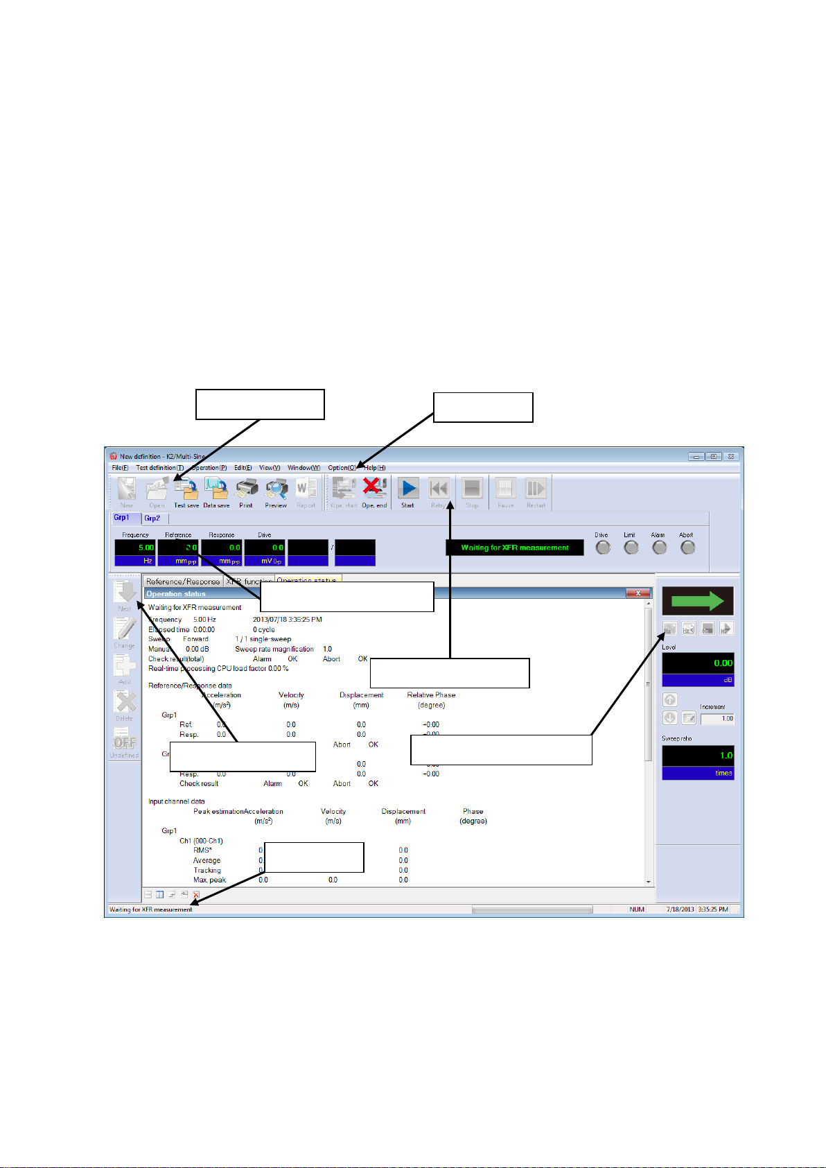
4.8 Operation Status .................................................................. 4-64

Chapter 5 Messages and Meanings .......................................................... 5-1
5.1 Multi-SINE Error Messages ......................................................... 5-1
Chapter 6 Supplemental Explanation ....................................................... 6-1
6.1 Timer ............................................................................. 6-1
6.2 Set Up ............................................................................ 6-2
6.3 Manual Operation .................................................................. 6-4
6.4 Using / Deleting of Live Data in Operation ........................................ 6-7
6.4.1 Using of Live Data in Operation ............................................. 6-8
6.4.1.1 Add the live data in operation at finishing the operation ............. 6-8
6.4.1.2 Add the live data in operation in Test definition mode ................ 6-10
6.4.2 Deleting of Live Data in Operation .......................................... 6-13
6.5 Skipping of XFR Measurement (Use the XFR Function of Live Data in Operation) ...... 6-14
6.6 Continuous XFR Measurement ........................................................ 6-17
6.7 Restarting suspended test ......................................................... 6-21

1 - 1
Chapter 1 Outline of the System
1.1 Specifications
1.1.1 Multi-SINE
(1) Control Method : ①Amplitude Control Portion :Level control of the swept sine waveform
by using the feed-back method
②Phase Control Portion:Real time waveform control by using the
feedforward method(Cross-talk control
between each axis)
(2) Control Frequency : 0.1~10,000 Hz (However it may be limited by conditions.)
(3) Frequency Resolution : Less than 10-4 of output frequency
(4) Control Dynamic Range : More than 114 dB
(5) Operation Mode
1) Sweep, Spot
2) Control variables : Response signal
(6) Sweep Operation
1) Sweep mode : Linear / Log
2) Sweep type : double / single
3) Direction : forward / backward
4) Manual operation at sweeping excitation pause / sweep pause, reversing of sweep direction,
excitation level change
(7) Test Time : by time / by sweep counts / by excitation times
(8) Input Channel (However it may be limited by conditions.)
1) Number of channels:maximum 64
(Including maximum 32 of ‘Principal Control Channels’)
2) Type of channels : Principal Control channel / Control channel / Monitor channel
(possible to duplicate)
3) Peak Amplitude Estimation Method : Averaged value, rms value, Tracking
4) Control Response Averaging Method : Averaged value control / Maximum value control /
Minimum value control
5) Alarm / Abort function : Level value of Alarm / Abort can be specified for each input
channel.
6) Limit Control Function : the maximum allowance profile data can be specified for each
input channel. When the response exceeding over the specified value is detected
at a concerning channel, the system controls this deviated response not to
exceeding over the level of allowance and continues the testing operation
without stopping. ‘Limit Control Option’ is necessary to use this function as
above.
1 - 2
(9) Output Channel : (However, it may be limited by conditions.)
1) Number of channels : maximum 16
2) Waveform distortion : Less than 0.1 % (1V rms)
(10) Analysis / Display Data
In Level measurement of Multi-SINE, it is assumed that the object signal for measurement is
the sine wave having the same frequency as the rated SINE force. Therefore, the DC signals
out of this assumption can not be measured.
1) The trace of the level for controlled response and response of each input channel
2) The trace of the level for drive
3) Each level data for every moments, accumulated value of the vibration times
4) Control response / Drive transmissibility, Each input channel / Controlled response
transmissibility
5) Distortion and Signal Tolerance of the Response signal to each input channels
6) The data of Transfer function between Principal Control channel and Drive Output
channel,Coherence
(11) Data save : 1) Automatic / Manual
2) Display data save as CSV format
(12) External Contact Function:
1) Input Part : Excitation start, Excitation stop, Pause, Restart, etc
2) Output Part : Waiting for excitation start, In excitation, In pause, Test
completed normally, Test completed in error
(13) Option : Limit Control
Display viewing of Multi-Sine

1 - 3
1.1.2 Limit Control (Option of Multi-SINE)
(1) Method
Observation Level is given to each limit control channel.
(2) Number of Channels
All the input channels are available to be used (however, the license is needed to be set.)
(3) Objective Physical Quantities
Physical quantity having a different unit from controlled variables is available to be used as a
Limit Control Channel.
2 - 1
Chapter 2 Operation System of K2 Application
2.1 Outline
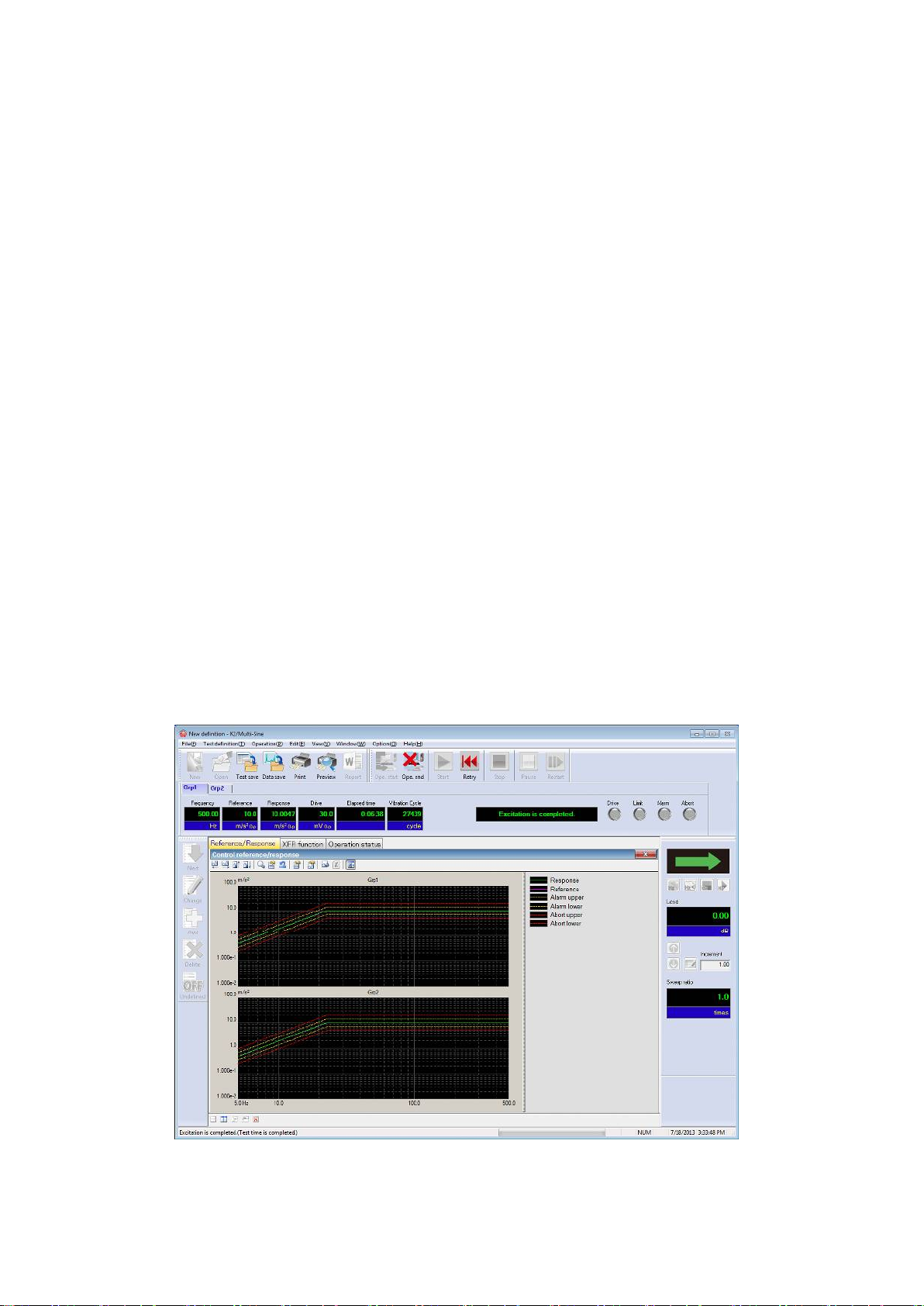
In K2 application, operation after booting up is executed by using a keyboard and a mouse.
When this application is started, a window shown as below appears.
All the names of menu in this application are displayed in Menu bar. Each menu is to be opened by
clicking on its name and available commands appears as a list.
The commands used frequently are displayed as icons in each Tool bar. A command is executed or a
dialog box corresponding to the command is opened when the icon is clicked. Operation status of K2
Controller is displayed in Status bar. The state during the excitation operation is displayed in Operation
status panel.
K2 Application Window
Operation tool bar
Operation status panel
Status bar
Definition tool bar Manual operation tool bar
File tool bar Menu bar

2 - 2
2.2 Test File
In K2 application, necessary information to operate a test is saved in a specified file called ‘Test file’ .
Following kinds of Test file are available in this system.
Necessary Test Files for test operation
・Test Definition File : The file created inVer10.0.0.0 or later
K2Multi-SINE(*.mswp2, *.mspt2)
The file created before Ver10.0.0.0
K2Multi-SINE(*.mswp, *.mspt)
・Graph Data File : The file created inVer10.0.0.0 or later(*.vdf2)
The file created before Ver10.0.0.0(*.vdf)
・Environment setting File
(I/O Module Configuration Information, Excitation System Information, Input channel
Information) : SystemInfo.Dat2
Note 1) Saved in ‘¥IMV¥K2_2nd’ on System Drive. Deleting inhibited
In K2 of the version before Ver.10.0.0.0, there are saved in ‘¥IMV¥K2’ on System
Drive.
In K2 of the version before Ver.6.0.0.0, there are saved in the Windows folder.
Note 2) If the K2 version is upgraded to Ver10.0.0.0 or later ones from previous ones, the
environment setting file will be automatically converted to the format for
Ver10.0.0.0 and later ones during installation.
2.3 Test Type
Two types of tests as below are available in K2 Multi-SINE.
①Sweep test
Sweep test is the most popular testing method used in sine vibration test. In this test, the system
operates the sine vibration control by changing the frequency continuously according to the
specified conditions.
②Spot test
In Spot test, the system operates the excitation of the specified condition in order by using the
excitation frequency and reference level specified beforehand.
Sweep operation is not executed in Spot. test
And, arbitrary setting of frequency series is possible in Spot test.

3 - 1
Chapter 3 Basic Operation
3.1 Sweep (Simplified definition)
< Example >
An example of sweep test is described as below ;(two shakers are used)
[Reference pattern]
[Test time]
Sweep rate : 1.000 (octave/min)
The times of double sweep : 1 (double-sweep)
[Information of sensors to be used]
Two acceleration pickups of piezoelectric :
ch1.:for Principal Control,sensitivity 3pC/(m/s2)
ch2.:for Principal Control,sensitivity 3pC/(m/s2)
However, these channels must be registered in Input enviroment information (in this example,
‘chtest1’).
Also, the rating information of excitation system has already been registered in Excitation system
information (in this example, ‘System1’).
Frequency [Hz]
Acceleration
[m/s2]
10
31.83
2000
20.0
Displacement:
1.0[mm]
3 - 2
< Procedures >
< Step 1 >
Press the button of [New] to start new definition.
< Step 2 >
Select the item of ‘Sweep’ in Test type.

3 - 3
< Step 3 >
Select an excitation system from the list of ‘Excitation System Information’.
< Step 4 >
Click the checkbox of ‘Input Environment Information’ and select an input environment information
from the list.
①
②

3 - 4
< Step 5 >
Press the [OK] button.
< Step 6 >
Press the button of [Next] to go to the next definition.

3 - 5
< Step 7 >
Press [OK].
< Step 8 >
Press the button of [Next] to go to the next definition.

3 - 6
< Step 9 >
Press [OK].
< Step 10 >
Press the button of [Next] to go to the next definition.

3 - 7
<Step11>
Select an excitation group among the available excitation groups. Here, select ‘Grp1’ and press the
button to add.
<Step12>
Input the values to ‘XFR loop check voltage‘ as 40 [mVrms].and ‘XFR function measurement
voltage’as 80.0 [mVrms]. Then press [OK].
①
②
①②
③
Other manuals for K2
5
Table of contents
Other IMV Measuring Instrument manuals


Popular Measuring Instrument manuals by other brands


humotion
humotion SmarTracks Diagnostics v.3.16 Installation guide & user manual

SEW
SEW 3800 CL instruction manual

General
General DCFM700 user manual

LaMotte
LaMotte WaterLink Spin Touch FF instruction manual

ESD
ESD 94390 Operation, installation, and maintenance manual

Würth
Würth EASY FINDER Translation of the original operating instructions


