IN-COMMAND Lite User manual

1
TROUBLESHOOTING GUIDE

2
TABLE OF CONTENTS
Table of Contents.............................................................................................................................................................................................................................................................................................................2
Introduction………………………………………………………………………………………………………………………………………………………………………………………………………………………………2
Body Control Module Wiring Diagram………………………………………………………………………………………………………………………………………………………………………………………………...3
Display Commander/Switch Plate Wiring Diagram………………………………………………………………………………………………………………………………………………………………………………….4
Body Control Module Pin Values………………………………………………………………………………………………………………………………………………………………………………………………….5 – 6
Paring a Mobile Device…………………………………………………………………………………………………………………………………………………………………………………………………………….7 – 8
Editing the Floor Plan…………………………………………………………………………………………………………………………………………………………………………………………………………………...9
Troubleshooting………………………………………………………………………………………………………………………………………………………………………………………………………………………..10
Introduction
The iN-Command Lite system is comprised of two parts; the BCM (Body Control Module) and either the DC (Display Commander) or SP (Switch
Plate). The iN-Command Lite system works in conjunction with the RV Switch Panel to provide remote app control for one light group and up to
seven motor functions. The DC or SP will automatically power on once power is applied.
This guide is made to ease troubleshooting the iN-Command Lite system. It will cover the wiring code and where those wires are connected on the
BCM (Body Control Module) and either the DC (Display Commander) or SP (Switch Plate), system functions, and what to look for to discern where
a problem could be.

3
Electric Wiring Guide for the BCM
BCM Pins 1-18 are on the Left side, ascending from Top to Bottom.
BCM Pins 19-36 on the Right side, ascending from Bottom to Top.
BCM Pins GND, RX, TX and +12V DC (DC RX/TX wires) are at the Top Right Side.
The TX (transmit) and RX (receive) connections at each device are crossed (crossover cable).

4
Electric Wiring for the DC/SP

5
BCM Pin Values
Pin Name BCM Function Note Amps DMM
Motor Switch Inputs
1
Motor 1 Out 12V from
Switch 12V for Motor 1 Extend Reversing Polarity DC Motor
30A
12V/GND
2 Motor 1 In 12V from Switch 12V for Motor 1 Retract Reversing Polarity DC Motor 12V/GND
3
Motor 2 Out 12V from
Switch 12V for Motor 2 Extend Reversing Polarity DC Motor 12V/GND
4 Motor 2 In 12V from Switch 12V for Motor 2 Retract Reversing Polarity DC Motor 12V/GND
5
Motor 3 Out 12V from
Switch 12V for Motor 3 Extend Reversing Polarity DC Motor 12V/GND
6 Motor 3 In 12V from Switch 12V for Motor 3 Retract Reversing Polarity DC Motor 12V/GND
7
Motor 4 Out 12V from
Switch 12V for Motor 4 Extend Reversing Polarity DC Motor 12V/GND
8 Motor 4 In 12V from Switch 12V for Motor 4 Retract Reversing Polarity DC Motor 12V/GND
9
Motor 5 Out 12V from
Switch 12V for Motor 5 Extend Reversing Polarity DC Motor 12V/GND
10 Motor 5 In 12V from Switch 12V for Motor 5 Retract Reversing Polarity DC Motor 12V/GND
11
Motor 6 Out 12V from
Switch 12V for Motor 6 Extend Reversing Polarity DC Motor 12V/GND
12 Motor 6 In 12V from Switch 12V for Motor 6 Retract Reversing Polarity DC Motor 12V/GND
13
Motor 7 Out 12V from
Switch 12V for Motor 7 Extend Reversing Polarity DC Motor 12V/GND
14 Motor 7 In 12V from Switch 12V for Motor 7 Retract Reversing Polarity DC Motor 12V/GND
Travel Lock 15 Lockout Signal In 12V 12V Inputfrom Tow Vehicle Brake Lock Out Motor Functions
when 12V Present 12V
Lighting I/O
16 Light 12V 15A In Input From Converter,Main
Breaker box
15A
12V
17 LightGND Just a Terminal, No PCB Trace
Needed GND
18 Light 12V 15A Out Output 12V From Pin 16 In 12V 12V
19 External Light Switch 12V In 12V Inputfrom External Switch 12V

6
Motor Outputs
20 Motor 7 In 12V for Motor 7 Retract Reversing Polarity DC Motor
30A
12V/GND
21 Motor 7 Out 12V for Motor 7 Extend Reversing Polarity DC Motor 12V/GND
22 Motor 6 In 12V for Motor 6 Retract Reversing Polarity DC Motor 12V/GND
23 Motor 6 Out 12V for Motor 6 Extend Reversing Polarity DC Motor 12V/GND
24 Motor 5 IN 12V for Motor 5 Retract Reversing Polarity DC Motor 12V/GND
25 Motor 5 Out 12V for Motor 5 Extend Reversing Polarity DC Motor 12V/GND
26 Motor 4 In 12V for Motor 4 Retract Reversing Polarity DC Motor 12V/GND
27 Motor 4 Out 12V for Motor 4 Extend Reversing Polarity DC Motor 12V/GND
28 Motor 3 In 12V for Motor 3 Retract Reversing Polarity DC Motor 12V/GND
29 Motor 3 Out 12V for Motor 3 Extend Reversing Polarity DC Motor 12V/GND
30 Motor 2 In 12V for Motor 2 Retract Reversing Polarity DC Motor 12V/GND
31 Motor 2 Out 12V for Motor 2 Extend Reversing Polarity DC Motor 12V/GND
32 Motor 1 In 12V for Motor 1 Retract Reversing Polarity DC Motor 12V/GND
33 Motor 1 Out 12V for Motor 1 Extend Reversing Polarity DC Motor 12V/GND
Power 34 Chassis GND GND GND
35 12V In Electric Motor Feed from Battery 30A 12V
36 12V In BCM Power from Converter 15A 12V
Display Commander
Link
37 12V Out 12V Out Connect to DC 12V
38 TX TX Out Connect toDC VDC
39 RX RX OutConnect to DC VDC
40 GND GND OutConnect to DC GND
The BCM should be wired correctly, without loose connections and +12VDC connected at pin 36. A RED LED will indicate that the BCM is powered
and receiving 12V. The DC or SP is connected to the BCM with 4 wires in the upper right corner of the board: ground, receiver, transmit and 12V
(GND, RX, TX, & 12V). When the SP is powered on, the RED and BLUE LED’s will stay lit while the SP is initializing. Once the LED’s turn off, the
SP is ready for operation. When the DC is powered on, initializing will appear on the display. Once initializing is replaced by iN-Command Lite on
the display, the DC is ready for operation.

7
Pairing the Mobile App
iN-Command Lite is able to pair with Android and iOS devices via the mobile app. Only one mobile device can be paired with iN-Command Lite at a
time.

8
To connect NCS50DC/SP with another device, perform the following steps:
NCS50SP: Long press “Bluetooth Pairing” button for 7 ~ 10 seconds to unpair device. NCS50SP will flash blue light twice when device is unpaired.
NCS50DC: In DC Menu, select unpair device and press the enter button. A message of “Are You Sure” will appear. Press “Enter” button again.
App: When powering down the App, select the box to “Unpair Device”.
Note: If unable to pair a device, go through the above steps to unpair a device, to make sure there is still not a device connected to the
NCS50DC/SP.

9
Editing the Floor Plan

10
Troubleshooting
Symptom
Solution
DC/SP will not turn on
Verify the BCM is powered on.
Check main fuse in Distribution Panel.
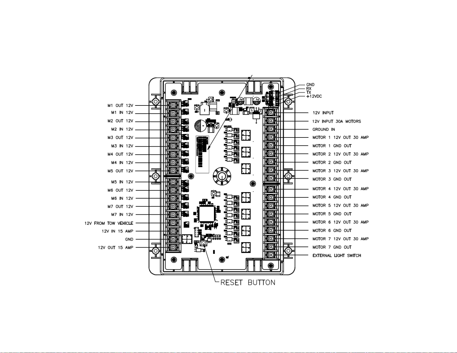
Verify red wire from BCM 12V (pin 37) is connected to 12V input on DC/SP.
Verify ground from BCM (pin 40) is connected to ground input on DC/SP
No Power to the BCM
Check if the RED power LED is on.
Check the main fuse in the Distribution Panel.
Check for 12V at pin 36.
Check for ground at pin 34.
Cycle power to the BCM
DC/SP Flashing On and Off
Ensure wires from BCM to DC are not damaged or pinched
Ensure wires are making contact with pins.
Press Reset button on BCM.
Cycle power to the BCM.
Light Group is not working Check 12V at pin 16 and ground at pin 17.
Check Light Group fuse in the Distribution Panel.
Motor Functions are not working Check 12V at pin 35.
Travel Lock is on (Motor Functions Disabled) Ensure 12V is removed from pin 15 (When the brakes are no longer being applied, or tow cable
is removed).
Press Reset button on BCM.
Functions not operating from DC/SP or App and
Battery voltage displays 0V Check to Ensure RX and TX wires are connected properly (RX from BCM connects to TX on
DC/SP; TX from BCM connects to RX on DC/SP).
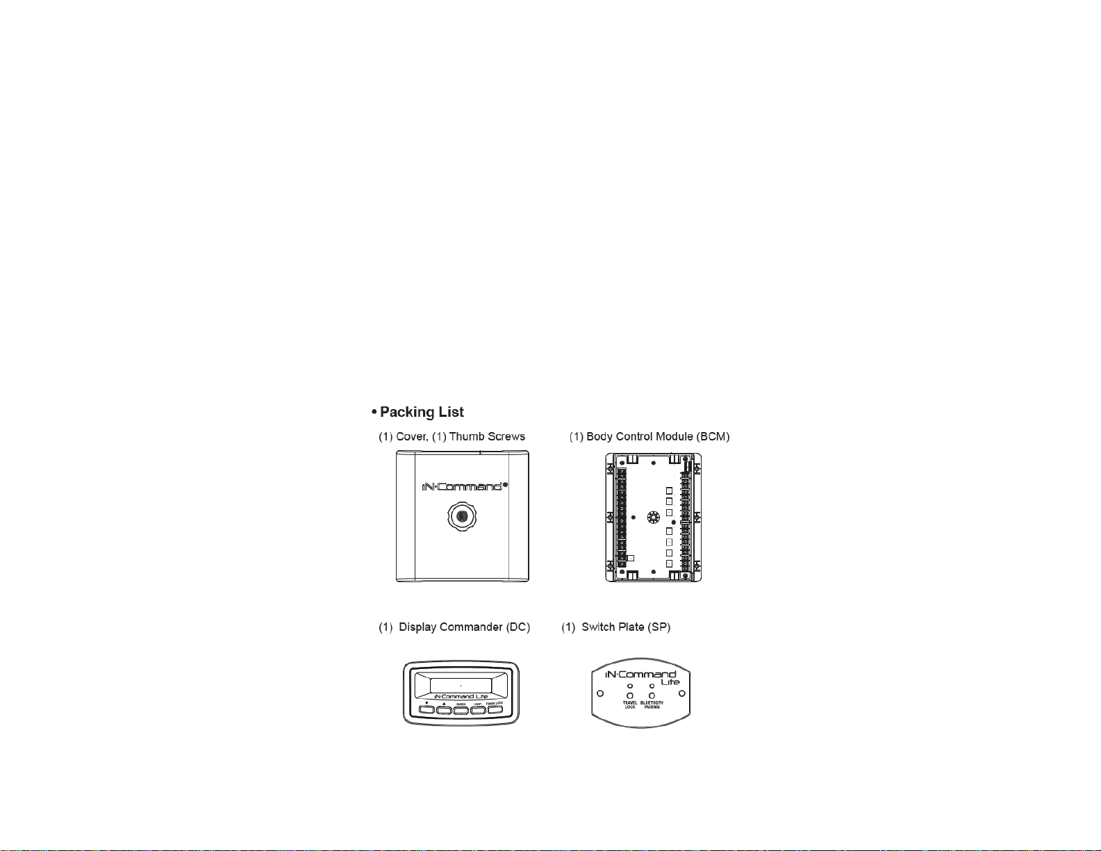
The NCS50 BCM with the SP/DC allows you to either use the RV Switch Panel or iN-Command App to control your RV’s functions. The BCM Pin
Values portion of this guide will clear most issues. Basically, if the BCM does not have the desired voltage, or signal input, it will not be able to
function or read battery voltage. Also, if the BCM has the correct output voltage, but nothing is functioning, the problem lies in the wiring leading to
the malfunctioning component or the component itself.
Any issues that are related to iN-Command that cannot be cleared using the above list will be tied to the BCM and DC hardware and software.
Careful inspection of the BCM will need to be done (possibly blowing the BCM board with air to remove any dust, debris, or conductive material). If
the BCM looks clean and undamaged (without burnt or cracked components) with all the wires secure and not touching each other, troubleshooting
the software is needed.
Contact an ASA representative 1-877-845-8750 for questions regarding iN-Command software or hardware issues.
Other manuals for Lite
1
Table of contents
Other IN-COMMAND Automobile Accessories manuals
Popular Automobile Accessories manuals by other brands

Kuda-Phonebase
Kuda-Phonebase 096380 Installation instruction

Xiaomi
Xiaomi Mi 20W Wireless Car Charger quick start guide

tams elektronik
tams elektronik FCS-3 manual

Curt Manufacturing
Curt Manufacturing 12113 installation instructions

ARM Motorsports
ARM Motorsports N63 FRONT FACING UPGRADE INSTALLATION GUIDE

PowerFleet
PowerFleet CELLOCATOR CR-100 manual