Incra Miter 3000 SE User manual

Manufactured by Taylor Design Group, Inc. P.O. BOX 810262 Dallas, TX 75381 ©2016 by Taylor Design Group, Inc. All rights reserved.
Before using the INCRA Miter3000SE, read and follow all of the instructions and safety information in this owner’s manual.
°When using the INCRA Miter3000SE in conjunction with any other tool, first read and follow all instructions and safety information
in that tool’s owner’s manual.
° Never let the saw blade come in contact with the aluminum or steel components of the INCRA Miter3000SE.
° When using the INCRA Miter3000SE, always keep your hands clear of the saw blade and the line of cut.
° Always turn offthe power and make sure that the saw blade comes to a complete stop before changing the setting of any part of the
INCRA Miter3000SE.
° Always securely tighten the large black clamping knob before starting any cut.
° Wear safety glasses, hearing protection, and follow all normal shop safety practices.
° After making any adjustments to the miter angle or fence position of your INCRA Miter3000SE, always verify safe clearance
between the blade and fence before turning on the saw.
° After making any adjustments to the fence position on the INCRA Miter3000SE, always make sure that the two socket head screws
are securely tightened.
° When using the INCRA Flip Shop Stop to position a piece for a cut, always hold or otherwise clamp the board between the stop
and the blade.
OWNER’SMANUAL
www.incra.com
Important safety instructions for using the INCRA Miter3000SE
Before using the INCRA
Miter3000SE, read and
follow all of the instructions
and safety information in
this owner’s manual.
by
SAFETY
INCRA MITER3000SE OWNER’S MANUAL
Manufactured by Taylor Design Group, Inc. P.O. BOX 810262 Dallas, TX 75381 WWW.INCRA.COM
Page 2
ASSEMBLY AND CALIBRATION
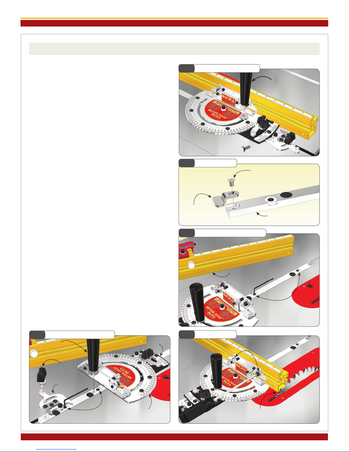
1. Attach Clamping Knob and T-Clip
Remove the hex bolt that secures that protractor head
and replace with the large threaded knob included in
the hardware pack. The washer on the hex bolt must
be used with the threaded knob, Fig. 1.
If the Miter slot in your table saw has a T-slot, attach
the T-clip to the end of the miter bar as shown in Fig. 2.
2. Adjust the Miter Bar
Loosen the (2) fasteners that secure the fence to the
fence mounting bracket and remove the fence. Adjust
the miter bar at each of the (4) expansion mechanism
locations for a good t in your table saw’s miter slot.
Turning the screw clockwise expands the mechanism.
You’ll nd (2) of the expansion locations in front of the
protractor. Adjust these (2) front expansion points
rst, expanding a little at each of the locations until
the bar slides smoothly, Fig. 3.
Remove the large clamping knob, and disengage the
rear actuator tooth from the 1/2° adjustment plate.
Pivot the protractor head to gain access to one of
the rear expansion points. To gain access to the fi-
nal rear expansion point, remove the rear actuator
thumbscrew and pivot the actuator, Fig. 4. After
adjustment, replace the rear actuator thumbscrew,
re-engage the rear actuator tooth to the 0° notch
on the 1/2° adjustment plate, then replace the large
clamping knob, washer and fence.
3. Attach the Fence
Place your Miter3000SE in the preferred miter slot at
your table saw. (Note: Left hand miter slot use shown.
See step 4 to convert fence for use in right hand mi-
ter slot.) Attached the fence to the fence mounting
bracket and slide the fence to a position that leaves
safe clearance between the end of the fence and the
blade. Tighten the (2) 1/4-20 fasteners, Fig. 5.
Fig. 1 Attach Clamping Knob
Fig. 2 Attach T-Clip
Fig. 3 Adjust Miter Bar - Front
Fig. 4 Adjust Miter Bar - Rear Fig. 5 Attach Fence
Threaded knob
Miter bar
#10-24x1/4”
Phillips at head
screw
T-clip
Fence removed
for access
Adjust (2) front
expansion points
Position fence for safe clearance
between fence and blade
Adjust (2) rear
expansion points
Large clamping knob 1/4-20 socket
head screws
Protractor head
pivoted for access
Rear actuator
Rear actuator
thumbscrew
1/2° adjustment
plate

INCRA MITER3000SE OWNER’S MANUAL
©2016 by Taylor Design Group, Inc. All rights reserved. Rev.1.16
Page 3
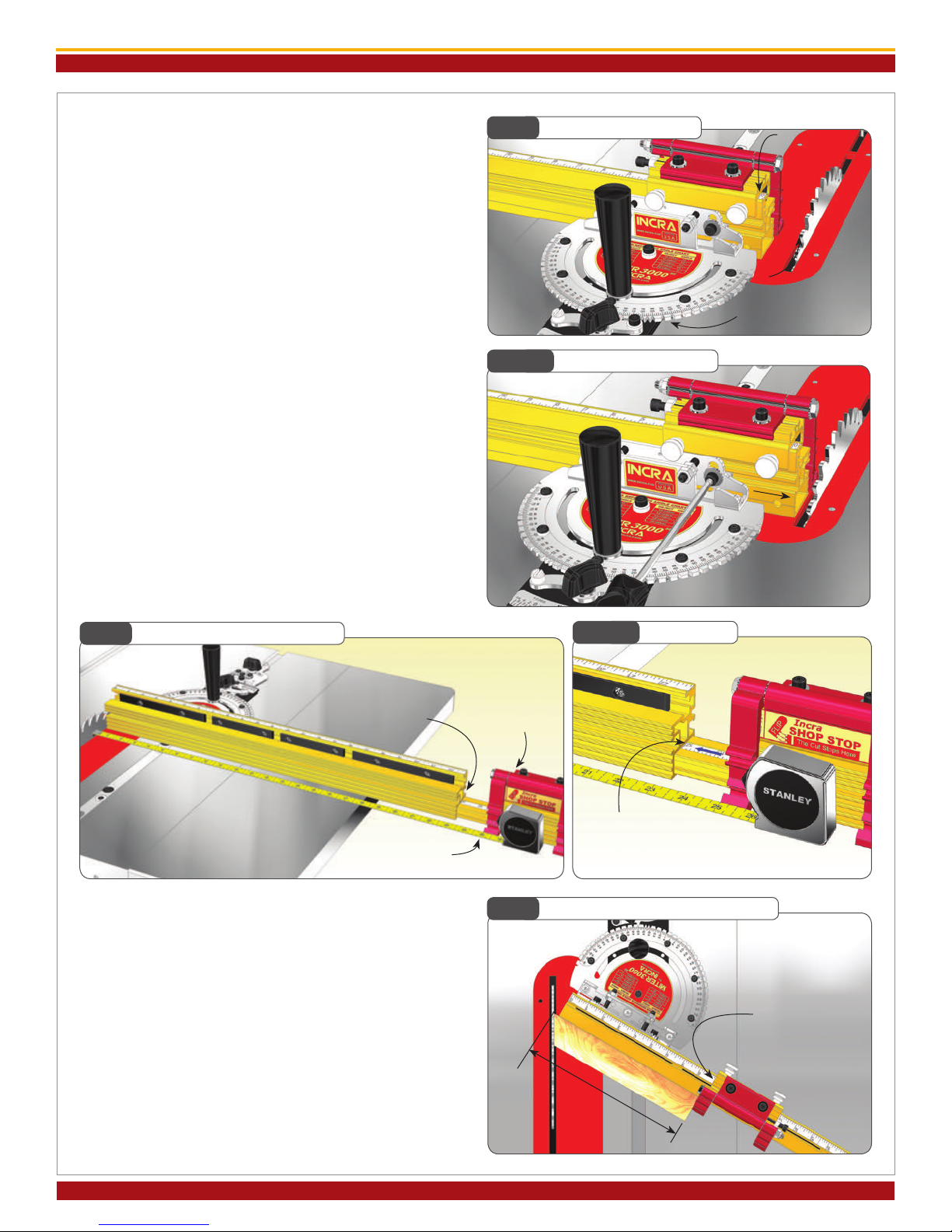
4. Left or Right of Blade
Your new Miter3000SE fence is factory congured for
use to the left of the blade. If you prefer to use your
Miter3000SE in the right hand miter slot just follow
the steps below.
Loosen the 1/4-20 socket head screw located at the
end of the 23” section of the fence, then slide out the
4” section of fence along with the attached extender
bar. Move the socket head screw, washer and rectan-
gular nut to the hole on the opposite end of the fence.
Slide the extender bar assembly into the end of fence,
capturing the rectangular nut in the T-slot on the ex-
tender bar. The higher numbers on the extender bar
scale should be closest to the saw blade. Loosen the
(2) socket head fasteners that secure the 4” section
of fence and reverse it. Tighten all fasteners, Fig 6.
Slide the scale in the top of the 23” fence out and re-
place with the included reverse reading scales.
TIP: About Your Fence Scales
All INCRA products use overlapping 16” long Lexan
scales. The overlap allows ne-tuning the scale from
one end to the other to agree with the high degree of
accuracy provided by the INCRA saw toothed posi-
tioning racks. As they are slid into the scale slot on the
fence, the ends are overlapped and aligned using the
optical window located at the end of the second scale.
The friction t will keep the scales in place. If you wish,
you can use a small piece of double faced tape at the
overlap to ensure that the scales move together when
changing your zeroed setups for mitering.
5. Adjust Fence Mounting Bracket 90°
to Saw Blade
Loosen the large clamping knob and make sure that
the rear actuator left hand tooth is engaged rmly
with the 0° notch on the 1/2° adjustment plate. Engage
the front actuator tooth with the 0° notch located on
the protractor head, Fig.7. Tighten the front actua-
tor thumbscrew then tighten the large clamping knob.
Using a Phillips head screw driver, loosen the (3)
Phillips head screws that secure the fence-mounting
bracket to the protractor head. Unplug your table
saw, then use a reliable machinist square to set the
fence at 90° to the saw blade, Fig. 8. Tighten the (3)
Phillips head screws.
This one time calibration prepares your INCRA Mi-
ter3000SE for work in either miter slot. Just remem-
ber that the accuracy of the INCRA Miter3000SE at
any subsequent setting is dependent upon the accura-
cy of your initial 90° calibration. Verify this im-
portant calibration with a test cut and ne
tune as necessary.
Fig. 6 Converting Fence for Use on Right Side of Blade
Fig. 7 Lock Front and Rear Actuator to 0°
Fig. 8 Adjust Fence Bracket 90° to Saw Blade
Move fasteners to opposite
end of fence
4” fence
section
Extender
bar
Remove
extender bar
assembly
1/2° adjustment
plate
Loosen (3) Phillips head screws
Rear actuator
left hand tooth
Front actuator tooth
Square
fence to blade
TIP About Your Fence Scales
Overlap scales as you slide into
scale slot
Optical window used
for proper alignment

INCRA MITER3000SE OWNER’S MANUAL
Manufactured by Taylor Design Group, Inc. P.O. BOX 810262 Dallas, TX 75381 WWW.INCRA.COM
Page 4
OPERATION – CHANGING ANGLE SETTINGS
The dual actuator design of the INCRA Miter3000SE provides two levels of adjustment. The front actuator is
used for coarse adjustments (5°), while the rear actuator is used for ne adjustments (1/2°). For most mitering
work, you’ll have the left hand tooth of the rear actuator engaged at the 0° notch, while you make angle changes
using only the front actuator. When using the rear actuator for ne adjustments, you are simply adding or sub-
tracting from the coarse adjustment setting.
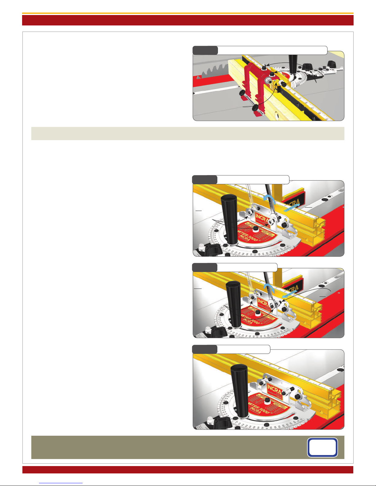
6. Calibrating the 1/2° Indexing Tooth
The 1/2° indexing tooth located on the rear actuator
is factory calibrated and should require no further ad-
justment. Follow the instructions below should you
wish to check the calibration or re-calibrate.
Loosen the large clamping knob and the rear actua-
tor thumbscrew. Engage the left-hand tooth of the
rear actuator rmly with the notch marked “CAL”
on the rear scale and hold while you tighten the large
clamping knob, Fig. 9. Now pivot the rear actua-
tor to engage the right hand tooth with the notch
marked “CAL” on the rear scale, Fig. 10. If adjusted
properly, it will pivot perfectly into the notch. To
adjust, loosen the (3) socket head screws that secure
the tooth and ne tune the position to align with the
“CAL” notch. Pivot back and forth between the two
“CAL” notches to verify the calibration.
Fig. 9 Calibrating 1/2° Indexing Tooth Fig. 10 Pivot Actuator to Check Calibration
Large clamping knob
Fig. 12 5° Indexing - Re-engage Front Actuator
Fig. 11 5° Indexing - Disengage Front Actuator
1st: Loosen large
clamping knob
1. Loosen the large clamping knob and make sure that
the rear actuator left hand tooth is engaged in the 0°
notch on the 1/2° adjustment plate. Loosen the front
actuator thumbscrew and pivot the actuator tooth
away from the notches located on the protractor head,
Fig. 11.
2. Rotate the protractor head to the desired angle
then rmly engage the tooth on the front actuator with
the corresponding notch on the protractor head. The
actuator tooth should point directly to the desired an-
gle on the scale. Tighten the large clamping knob, then
tighten the front actuator thumbscrew, Fig. 12.
5° Indexing (including 22.5° and 67.5° settings)
Left-hand tooth of rear
actuator at 0°
1st: Rotate to desired
angle
3rd: Tighten large
clamping knob then front
actuator thumbscrew
Loosen (3) socket
head screws to adjust
if necessary
Engage rear actuator
left-hand tooth with “CAL”
notch then tighten large
clamping knob
Rear actuator thumbscrew
Pivot actuator to
conrm right-hand
tooth engages
smoothly into
“CAL” notch
2nd: Loosen front
actuator thumb-
screw and pivot
tooth away from
protractor
2nd: Engage front actuator
tooth with notch at desired
angle

INCRA MITER3000SE OWNER’S MANUAL
©2016 by Taylor Design Group, Inc. All rights reserved. Rev.1.16
Page 5
Fig. 13 1/2° Indexing - Engage Front Actuator
1. Loosen the large clamping knob. Loosen the front
actuator thumbscrew and pivot the actuator tooth
away from the notches located on the protractor head.
Rotate the protractor head and engage the front actua-
tor tooth at the 5° notch closest to the angle you want.
Tighten the front actuator thumbscrew, Fig. 13.
2. Loosen the rear actuator thumbscrew. Use the left-
hand tooth to add or subtract from the coarse adjust-
ment setting in 1° intervals. Use the right-hand tooth
to add or subtract from the coarse adjustment setting
in 1/2° intervals. Engage the tooth rmly in the select-
ed notch then tighten the large clamping knob and the
rear actuator thumbscrew, Fig. 14.
Important: After completing your cut don’t forget to
return the rear actuator setting to the 0° notch.
CAUTION:
AFTER MAKING ANY ADJUSTMENTS TO THE
MITER ANGLE OF YOUR INCRA MITER3000SE,
ALWAYS VERIFY SAFE CLEARANCE BETWEEN
THE FENCE AND THE BLADE BEFORE TURN-
ING ON THE SAW.
1/2° Indexing
1st: Loosen large
clamping knob
3rd: Tighten thumbscrew
Fig. 14 1/2° Indexing - Engage Rear Actuator
1st: Loosen rear actuator
thumbscrew
2nd: Engage right or
left-hand tooth to add or
subtract 1/2° increments
3rd: Tighten
large clamping
knob and rear
actuator thumbscrew
For angle settings ner than the 1/2° settings, rst use the 1/2° indexing instructions above to locate the protrac-
tor head as close as possible to the desired angle. With the large clamping knob loosened, pivot the rear actuator
tooth slightly away from the notch on the 1/2° adjustment plate. Rotate the protractor head in the direction of
required adjustment and tighten the large clamping knob. Do not tighten the rear actuator thumbscrew. As with
any mitering tool, odd angle adjustments may require a little trial and error.
Continuous Adjustments
FLIP FENCE AND FLIP SHOP STOP - CALIBRATION AND OPERATION
As you look at your new INCRA Flip Shop Stop and
Flip Fence for the rst time you will see an interesting
detail. The front face of the fence uses a tongue and
groove arrangement to accept a mating feature on the
ip arms, Fig. 15. When the ip arm is down with
the two opposing features engaged, it becomes im-
possible for the sharp corner of a mitered board end
to wedge between the fence and ip arm. Combined
with INCRA’s famous incremental positioning capa-
bilities, you’ll soon be duplicating cut off lengths with
machine shop precision.
Fig. 15 Flip Shop Stop
Tong ue and groove
2nd: Loosen front actuator
thumbscrew and engage
tooth with 5° notch closest
to your desired angle
INCRA MITER3000SE OWNER’S MANUAL
Manufactured by Taylor Design Group, Inc. P.O. BOX 810262 Dallas, TX 75381 WWW.INCRA.COM
Page 6
Zeroing the Fence Scales
To zero the main fence scale for 90° work, rst set
the protractor to the 0° setting and lock in place.
Clamp the Flip Shop Stop to the fence so that the 0”
mark on the fence scale reads directly under the end
of the gold component of the Flip Shop Stop, Fig. 16.
Now loosen the (2) 1/4-20 socket head screws that
secure the fence to the fence mounting bracket and
slide the fence toward the blade until the Flip Arm on
the stop contacts the blade. Re-tighten the fasteners,
Fig. 16A.
For stopped cuts beyond the range of the main fence
you’ll need to calibrate the extender bar scale. Clamp
the INCRA Flip Shop Stop to the 4” fence extend-
er. (Use the scale on the short section of fence as a
reference for clamping the stop to the same position
each time you use it.) Now loosen the 1/4-20 socket
head screw located at the end of the longer fence and
slide the 4” fence and extender bar out. Use a tape
measurer to set the distance between the blade and
the Flip Arm at 25” and re-tighten the fastener, Fig. 17.
Now simply slide the scale in the extender bar to read 25”
at the end of the longer main fence section, Fig. 17A.
Fig. 16 Zeroing Fence Scale
Fig. 17 Setting Extender Bar Scale
Clamp Flip
Shop Stop at
0” position
Protractor set at 0°
Fig. 16A Slide Fence to Blade
Slide fence until ip
arm contacts blade
then tighten
fasteners
Fig. 17A Align Scale
Slide scale to read
25” at the end of
main fence
Fig. 18 Setting Scales for Angled Cuts
Loosen extender
bar fastener Clamp stop to 4”
section
Slide extender bar out until
ip arm is 25” from blade then
tighten fastener
For mitered cutting, a test cut is often the most accurate
means of setting the fence and extender bar scales since
measuring to the tooth of a blade set at an angle to the
fence can be difcult. Begin by setting the desired miter
angle and check for safe clearance between the fence and
blade. Clamp the stop to the fence about 10” away from
the blade. Miter a piece of scrap stock with this setup.
Measure the length of the cut piece, Fig. 18. Then sim-
ply slide the scale on the fence to read the length of the
cut directly under one end of the stop.
Slide scale to read
cut length here
Measure
length of cut

INCRA MITER3000SE OWNER’S MANUAL
©2016 by Taylor Design Group, Inc. All rights reserved. Rev.1.16
Page 7
Micro Adjusting
To micro adjust your Flip Shop Stop’s position, begin by
loosening the (2) socket head screws located on the top
of the stop body. Now turn the micro adjust socket head
screw to ne tune the stop position, Fig. 19. When un-
screwing the micro adjust screw, apply pressure to the
stop body to keep it against the screw end. After adjust-
ment, always tighten the (2) socket head screws on top
of the stop body.
Flip Arms and Stop Rods
The dual ip arms and stop rods provide a variety of
stop congurations. The ip arms can be used without
the stop rods when you want to take advantage of the
fence/arm tongue and groove feature for stop control on
mitered board ends. Typically, you will use the longer
rod to join the two arms together, Fig. 20. This pro-
duces an arrangement that, when pivoted, moves both
arms simultaneously. The rod can be positioned so that
it is the actual stop surface or it can be positioned slight-
ly behind the front of the arm so that the aluminum arm
is the actual stop surface.
By placing one of the shorter 1-1/2” rods in each of the
two stop arms, you can use the two stop arms inde-
pendently, Fig. 21. For example, you can calibrate one
for work to the left of the blade and the other for work
to the right. On one side of the blade you might want to
position the stop rods to provide two different cut off
lengths from one stop position. By using varying combi-
nations of long or short rods you can create as much as
7-3/4” between the two stop positions.
Making a Zero Clearance Wooden Sub-Fence
A sub-fence can be used to provide tear out control as
well as support for your workpiece up to and beyond
the blade. A good material to use for making your zero
clearance sub-fence is 3/4” medium density berboard
(MDF). Use the drill and counter bore dimensions
shown in Fig. 22. Attach using the supplied fasteners.
Adjust the length of the fence to accommodate your ap-
plication. Note: In applications where the incremental
stopping capability of the Flip Shop Stop is required, the
wooden sub fence can be no taller than 2-1/2”.
Fig. 19 Micro Adjusting
Loosen (2) socket
head screws
Turn this s oc ket head
screw to adjust
Fig. 20 Long Stop Rod
Long stop rod used to join
ip arms
Fig. 21 Short Stop Rods
Short stop
rods allow
independent
ip arm use
Fig. 22 Making a Sub-Fence
2-1/2” max (see note)
5/16” through hole
w/ 3/4” dia. x 3/8”
deep counter bore
To avoid the saw blade pulling your workpiece
into the cut, add a strip of adhesive backed sand-
paper to the front face of the wooden sub fence
TIP
1/4-20 rectangular
nut
1-1/16”
3/4”
1/4” at washer
1/4-20 x 3/4” socket
head screw
©2016 by Taylor Design Group, Inc. All rights reserved. Rev.6/16
Page 8
Manufactured by Taylor Design Group, Inc. P.O. BOX 810262 Dallas, TX 75381 WWW.INCRA.COM
MADE IN THE
USA
Taylor Design Group, Inc. P. O. B O X 810 2 6 2 D al la s, T X 75 3 81 P: 9 7 2 -2 4 2 - 9 97 5 F: 97 2 - 2 4 2 - 9 98 5 www.incra.com
INCRA is a Registered Trademark of Taylor Design Group, Inc. ©2016 Taylor Design Group, Inc.
INCRA MITER3000SE OWNER’S MANUAL
Fig. 23 Expanded Flip Stop Clamping Mode
Fig. 24 To Ti lt Fe nce Fo r wa rd
Your INCRA Miter30 00SE Fence has been adjusted square to the table at the factory so
no further adjustment should be required. If adding a wooden sub-fence, ne adjust-
ments to the angle can be easily made as described below.
Loosen
socket head
screws
Slide red assembly
into 2nd T-slot on
gold component
1st: Loosen
both outside
nuts
Expanded Flip Stop Clamping Mode
The two-part body design of the INCRA Flip Shop Stop
allows for use with up to a 3/4” thick wooden sub-fence.
To expand the INCRA Flip Shop Stop, loosen the (2)
socket head screws located on the top of the stop body,
then slide the upper portion of the stop off. Now slide
the upper portion back on, capturing the rectangular
nuts in the second T-slot located on the lower portion
(gold component) of the stop body, Fig. 23.
ADJUSTABLE FENCE MOUNTING BRACKET
Fig. 25 To Ti lt Fe nc e Bac k
2nd: Rotate 1/6
turn as shown,
alternating
between 2 out-
side nuts until
square
Fig. 26 To Loc k Se tt in g
After adjustment,
re-tighten the
remaining
loose nuts
Incra’s fence mounting bracket enables any fence to be
quickly and easily adjusted for perfect squareness to
the table. We have provided two adjustment points
so you can also neutralize twist or thickness variation
that is sometimes present in homemade wooden fenc-
es or sub-fences.
1) Place a square against the front face of your fence.
If you see a gap between the top of the fence and your
square rst loosen both outside nuts. Tighten one of in-
side nuts about 1/6 turn against the rear leg of the brack-
et as shown in Fig. 24, and then tighten the other inside
nut by the same amount in the same direction against
the rear leg. Alternate this 1/6 turn procedure between
the two nuts until the fence is perfectly square to the ta-
ble. DO NOT TURN THE SET SCREW and DO NOT
over tighten the nuts. It usually takes less than one full
turn of the nuts to square your fence to the table.
If you see a gap between the bottom of your fence and
the square, rst loosen both inside nuts. Tighten one of
outside nuts about 1/6 turn against the rear leg of the
bracket as shown in Fig. 25, and then tighten the other
outside nut by the same amount in the same direction
against the rear leg. Alternate this 1/6 turn procedure
between the two nuts until the fence is perfectly square
to the table. DO NOT TURN THE SET SCREW and
DO NOT over tighten the nuts. It usually takes less
than one full turn of the nuts to square your fence to the
table.
2) After the fence has been squared to the table as de-
scribed above, tighten both of the loose nuts against the
rear leg of the bracket to secure your setting, Fig. 26.
DO NOT TURN THE SET SCREW.
2nd: Rotate 1/6 turn
as shown alternating
between 2
inside
nuts until
square
1st: Loosen
both inside
nuts
Other Incra Measuring Instrument manuals

Popular Measuring Instrument manuals by other brands


Samoa
Samoa 383 401 Parts and technical service guide

Keysight Technologies
Keysight Technologies M9260A Startup guide

Marsh-McBirney
Marsh-McBirney Flo-Mate 2000 Installation & operation manual

Dräger
Dräger Aerotest Alpha Instructions for use

HBK
HBK 2255 instruction manual

PreSens
PreSens pH-10 mini instruction manual


