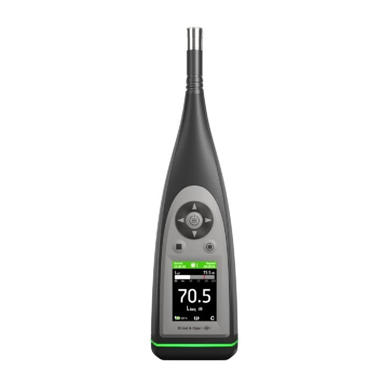
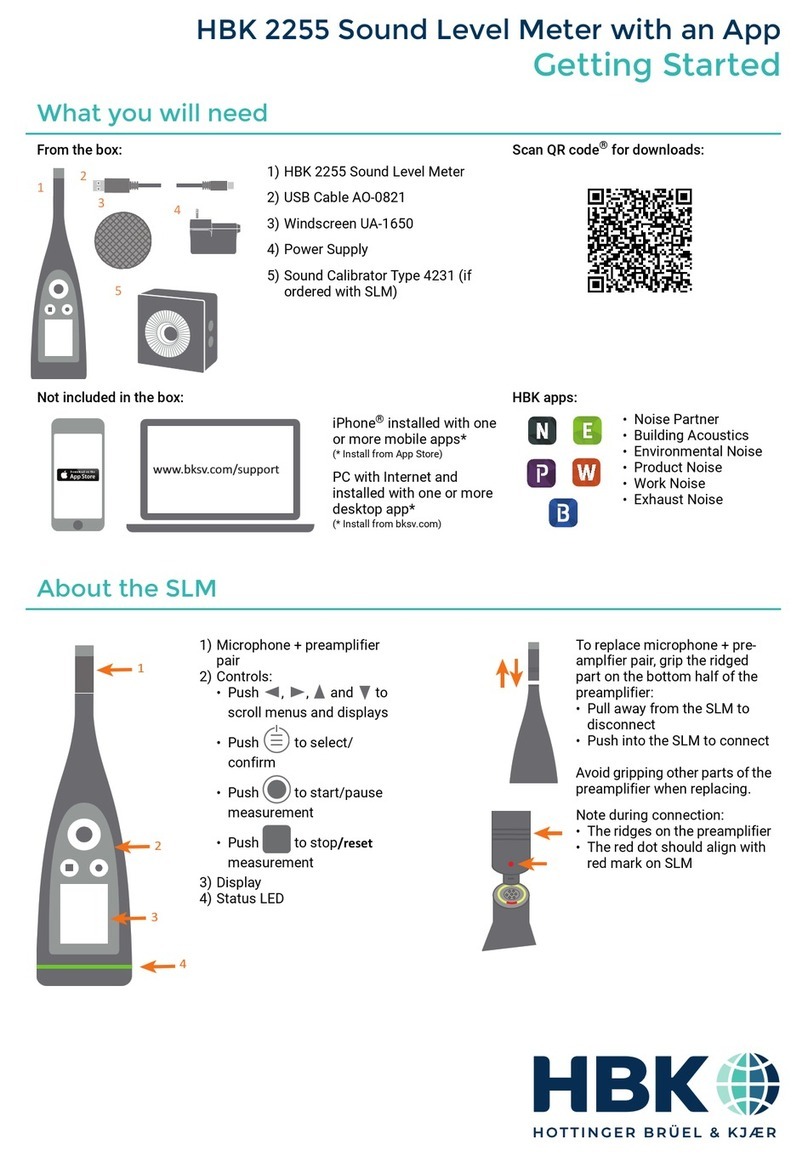
HBK 2255 User manual


Sound Level Meter Type 2255 –
Instruction Manual
Page 2 of 133

Sound Level Meter Type 2255 –
Instruction Manual
Page 3 of 133
Contents
Table of Contents
Chapter 1 Introduction....................................................................................6
1.1 About This Manual...............................................................................6
1.1.1 Conventions Used in this Manual ................................................6
1.2 System Overview ................................................................................7
1.2.1 Hard ware and Firm ware on the Sound Level Meter ......................7
1.2.2 Basic PC Software .....................................................................7
1.2.3 Hard ware Setup .........................................................................7
1.2.4 Block Diagrams........................................................................ 10
Chapter 2 Short Guide to the Sound Level Meter ........................................... 11
2.1 Introduction....................................................................................... 11
2.2 Switching the Sound Level Meter On and Off ...................................... 11
2.3 Setting Up the Sound Level Meter ...................................................... 11
2.3.1 About...................................................................................... 12
2.3.2 Measurement Settings.............................................................. 12
2.3.3 Display Settings....................................................................... 15
2.3.4 System Settings....................................................................... 16
2.3.5 Status ..................................................................................... 19
2.4 Calibration ........................................................................................ 20
2.4.1 Calibration Procedure............................................................... 20
2.4.2 Calibration Check Procedure .................................................... 22
2.5 Measuring with the Sound Level Meter ............................................... 24
2.5.1 The Display During Measurement ............................................. 24
2.5.2 Start, Pause and Stop of Measurement ..................................... 24
2.5.3 Overload and Underrange ........................................................ 25
2.6 Viewing Measurements ...................................................................... 25
2.7 Viewing Saved Measurements ........................................................... 26
2.8 Positioning the Microphone ................................................................ 26
2.9 Mounting the Microphone/Sound Level Meter on a Tripod .................... 27
2.10 Measuring Low-level Sounds.............................................................. 27
2.11 Measuring at Low Static Pressure....................................................... 28
2.12 Mechanic al Vibration ......................................................................... 29
2.13 Frequency Weightings ....................................................................... 29
2.14 Measured Quantities.......................................................................... 30
2.14.1 Instantaneous Broadband Measurements .................................. 30
2.14.2 Timed Broadband Measurements ............................................. 33
2.14.3 Spectrum Measurements.......................................................... 36
2.14.4 Instantaneous Spectrum Measurements .................................... 36
2.14.5 Timed Spectrum Measurements ............................................... 37
2.15 Overload and Underrange .................................................................. 37
2.15.1 Overload ................................................................................. 37
2.15.2 Underrange ............................................................................. 38
Chapter 3 Conformance Testing.................................................................... 39
3.1 Introduction....................................................................................... 39
3.2 Microphone, Accessories and Sound Fields ........................................ 39
3.2.1 For Acoustical Tests................................................................. 39
3.2.2 For Electrical Tests .................................................................. 39
3.3Calibration during Pattern Evaluation and Periodic Tests...................... 39
3.3.1 Acoustic Calibration ................................................................. 39
3.3.2 Electrical Substitute for Microphones......................................... 40

Sound Level Meter Type 2255 –
Instruction Manual
Page 4 of 133
3.4 Wi-Fi and Bluetooth During Tests ....................................................... 40
3.5 Mounting f or Acoustical Tests............................................................. 40
3.6 Periodic Testing of Acoustical Frequency Responses .......................... 41
3.7 Mounting f or Mechanical Vibrations Tests ........................................... 41
3.8 Testing 1/1-octave Band and 1/3-octave Band Filters........................... 41
3.9 EMC Test Procedures........................................................................ 42
3.9.1 Signal So urces f or Immunity Test .............................................. 42
3.9.2 Ref erenc e Orientatio n .............................................................. 42
3.9.3 Securing of Cables during EMC Test ......................................... 43
3.9.4 Accessories Included in EMC Test ............................................ 43
3.9.5 Normal Mode of Operation during EMC Test.............................. 43
Chapter 4 Specif ications............................................................................... 46
4.1 Specif ications.................................................................................... 46
4.2 Standards ......................................................................................... 46
4.3 Ref erenc e Environment al Conditions .................................................. 46
4.4 Ref erenc e Conditions for Acoustic Calibration ..................................... 47
4.5 Microphone....................................................................................... 47
4.6 Frequency Responses ....................................................................... 48
4.6.1 Electrical Frequency Responses ............................................... 48
4.6.2 Typical Low-f requency Responses ............................................ 49
4.6.3 Acoustical Frequency Responses ............................................. 50
4.6.4 Free-f ield Frequency Respo nses .............................................. 50
4.6.5 D iff use-f ield Frequency Responses ........................................... 52
4.6.6 Free-f ield Frequency Responses f or Dif f use-f ield
Calibrated Instruments ............................................................. 52
4.7 Directional Responses ....................................................................... 53
4.8 Self -generated Noise ......................................................................... 64
4.8.1 Maximum Broadband Self -generat ed Noise............................... 64
4.8.2 Typical Broadband Self -generated Noise................................... 64
4.8.3 Typical Self-generated Noise Spectra........................................ 65
4.9 Measuring Ranges ............................................................................ 66
4.9.1 Maximum Sound Level ............................................................. 66
4.9.2 Total Range............................................................................. 66
4.9.3 Primary Indicator Range ........................................................... 66
4.9.4 Indicator Range ....................................................................... 67
4.9.5 Linearity Range........................................................................ 67
4.9.6 Pulse Range............................................................................ 68
4.9.7 Linear Operating Range ........................................................... 68
4.9.8 Peak C Range ......................................................................... 68
4.10 Detectors .......................................................................................... 69
4.10.1 Exponential Averaging.............................................................. 69
4.10.2 Linear Averaging...................................................................... 70
4.10.3 Peak ....................................................................................... 70
4.11 Spectrum Analysis............................................................................. 70
4.11.1 1/1- octave Band Centre Frequencies ....................................... 70
4.11.2 1/3-octave Band Centre Frequencies ........................................ 71
4.11.3 Linear Operating Range ........................................................... 72
4.11.4 Measurement Range................................................................ 72
4.11.5 Octave Band Time Constants ................................................... 73
4.12 Inf luence f rom the Operating Environment .......................................... 73
4.12.1 Environmental Stabilisation Time .............................................. 73
4.12.2 Temperat ure ............................................................................ 73
4.12.3 Humidity.................................................................................. 73
4.12.4 Vibration.................................................................................. 73
4.13 Wirel ess Interf ace to the Sound Level Meter ....................................... 74
4.13.1 Bluetooth................................................................................. 74

Sound Level Meter Type 2255 –
Instruction Manual
Page 5 of 133
4.13.2 Wi-Fi ....................................................................................... 74
4.13.3 Regulatory Information............................................................. 74
4.14 Electrical Interface to the Sound Level Meter....................................... 75
4.14.1 Voltage Output......................................................................... 75
4.14.2 Digital Interf aces ...................................................................... 76
4.14.3 Charge / Po wer Interf ace .......................................................... 76
4.15 Power Supply.................................................................................... 76
4.15.1 External AC Main Power Supply Adapter................................... 76
4.15.2 Battery .................................................................................... 77
4.16 Warm-up Time .................................................................................. 77
4.17 Real-time Clock ................................................................................. 77
4.18 Mark Compliance .............................................................................. 78
Appendix A Tables...................................................................................... 80
A.1 Electrical Frequency Responses......................................................... 80
A.2 Free-f ield Frequency Responses ........................................................ 82
A.3 D iff use-f ield Frequency Responses .................................................... 87
A.4 Free-f ield Frequency Responses f or Dif f use-f ield Calibrated
Instruments ....................................................................................... 90
A.5 Directional Responses ....................................................................... 92
A.6 Periodic Testing of Acoustical Frequency Responses ........................ 124
Appendix B Cross-ref erences to Standards ................................................ 126
B.1 Introduction..................................................................................... 126
B.2 Cross-ref erences to Standards ......................................................... 126
B.3 Irrelevant Topics.............................................................................. 133

Sound Level Meter Type 2255 –
Instruction Manual
Page 6 of 133
Chapter 1
Introduction
1.1 About This Manual
This instruction manual for Sound Level Meter Type 2255 with Microphone Type 4966 has been
created to fulfil the documentation requirements of the national and international standards
that the sound level meter and this microphone conform to. These standards are listed in
section 4.2.
For other microphone configurations, there are a number of supplements to this manual that
give the relevant information for those configurations.
Other documentation and sales material will also contain specifications for the sound level
meter. In the event of any unintended inconsistencies between these and the specifications in
this instruction manual, the instruction manual takes precedence.
Appendix B of this manual provides cross-references between specific paragraphs in the
standards that require topics to be documented and the corresponding sections in this manual
that conform to them.
The PC and smart device software contain online help including user help for the sound level
meter.
1.1.1 Conventions Used in this Manual
The term “sound level meter” is an abbreviation for "Sound Level Meter Type 2255",
"microphone" is an abbreviation for "Prepolarized Free-field ½" Condenser Microphone Type
4966", and "windscreen" is an abbreviation for "90 mm dia. Windscreen with auto-detect insert
UA-1650" throughout this manual.
Selectable Buttons, Values and Pages on the Screen and Command
Indicated by bold typeface (for example: select Enabled).
Parameters, Text and Variable Fields
Parameters, instructions, descriptions appearing on the screen and variables are indicated by
italics (for example: select as
Input
).
Menus and Screen Navigation
Indicated by bold typeface and arrows (for example, go to Measurement settings > Input >
Sound field).
Notes and Hints
Please note: Notes contain nice-to-know information that does not convey possible risks to
the user or sound level meter.
Hint: Hints are suggestions or tips to help the user avoid typical problems, or to perform tasks
easier and/or correctly.

Sound Level Meter Type 2255 –
Instruction Manual
Page 7 of 133
1.2 System Overview
1.2.1 Hardware and Firmware on the Sound Level Meter
To see the currently installed firmware and hardware on the sound level meter, go to the About
screen. See section 2.3.1.
There are three firmware variants:
•FW-2255-000: General type-approved firmware
•FW-2255-001: WELMEC type-approved firmware, Germany
•FW-2255-002: WELMEC type-approved firmware, Spain
The three firmware variants fulfil the specifications described in this manual.
The FW-2255-000 variant is a superset of the other variants.
The three firmware variants are identical, except for the following restrictions on FW-2255-001
and FW-2255-002 compared to FW-2255-000:
•Installing and updating firmware can only be done by authorized personnel
•Measurements cannot be performed if the Clock has been reset and not automatically
set afterwards (FW-2255-000 gives a warning)
•Measurements cannot be opened if a checksum on data fails (FW-2255-000 gives a
warning)
In addition, the following restrictions have been made to FW-2255-002:
•Changes to microphone parameters can only be made by authorized personnel (created,
modified and deleted)
•Calibration with changes to the sensitivity can only be made by authorized personnel
•The maximum allowed deviation from initial sensitivity of microphone is ±1.1 dB (instead
of ±1.5 dB)
•Date format can only be dd/mm/YYYY or dd-mm-YYYY
•Time format can only be HH:mm:ss
•Decimal point can only be “,” (comma)
•Saved legally relevant data can first be deleted after a 2-year retention period
1.2.2 Basic PC Software
Noise Partner for PC can be used for transferring measurement data from the sound level meter
to a standard PC for post-processing and reporting.
Noise Partner for smart devices can be used for controlling the sound level meter and for
transferring data from the sound level meter to the smart device for display and post-
processing.
Noise Partner can be downloaded from the Brüel & Kjær website. For instructions on using this
software, see the software’s online help.
1.2.3 Hardware Setup
This section provides an overview of the hardware components used with the sound level meter.
A hardware overview is provided in Fig. 1.1; optional accessories are included in the figure.
The components needed for conformance testing of the sound level meter are listed in Table
1.1. The accessories that can be used for an approved measurement with this software version
are listed in Table 1.2.

Sound Level Meter Type 2255 –
Instruction Manual
Page 8 of 133
Fig. 1.1 Hardware overview

Sound Level Meter Type 2255 –
Instruction Manual
Page 9 of 133
Table 1.1 Hardware components needed for conformance testing of Sound Level Meter Type 2255
Quantity
HBK Part Number
Description
1
Type 4966
Prepolarized Free-field ½" Condenser Microphone
1 ZC-0043 Microphone Preamplifier
1 WA-0302-B Electrical Substitute for Microphone Type 4966, 15 pF
1
UA-0245
10–32 UNF to BNC Adapter
1 UA-1650 90 mm dia. Windscreen with auto-detect insert
1AO-0414-D-100 Microphone Extension Cable, 7-pin LEMO, 10 m
1 UA-1317 Microphone Holder
1
UA-1651
Tripod Extension
1 UA-2238 Tripod Adapter
1
ZG-0486
Power supply with integrated USB-A socket
1
AO-0821-D-010
USB Shielded I/O Cable, Type A-to-C, USB 2.0, 1 m
1 AO-0846 USB-C
®
to 3.5 mm Mini Jack Adapter, shielded, for
analogue headphones
1
Type 4231
Sound Calibrator
1 Type 4226 Multifunction Acoustic Calibrator
Table 1.2 Accessories that can be used for an approved measurement with this software version
Software
Version
HBK Type/Part
Number Description
1.2.0.1151
Type 4966 Prepolarized Free-field ½" Condenser Microphone
ZC-0043 Microphone Preamplifier
UA-1650
90 mm dia. Windscreen with auto-detect insert
AO-0414-D-100 Microphone Extension Cable, 7-pin LEMO, 10 m
UA-1317 Microphone Holder
UA-0049 Microphone Extension Rod
UA-1651 Tripod Extension
UA-2238 Tripod Adapter
ZG-0486
Power supply with integrated USB-A socket
AO-0821-D-010
USB Shielded I/O Cable, Type A-to-C, USB 2.0, 1 m
AO-0846 USB-C
®
to 3.5 mm Mini Jack Adapter, shielded, for
analogue headphones
Type 4231 Sound Calibrator

Sound Level Meter Type 2255 –
Instruction Manual
Page 11 of 133
Chapter 2
Short Guide to the Sound Level Meter
2.1 Introduction
This chapter contains a brief guide to the use of the sound level meter.
The user interface of the sound level meter has:
•A screen for displaying settings, results and status
•A keyboard for navigating on the screen, changing settings and controlling the
measurement
•A colour-coded light ring that reflects the status of the instrument
2.2 Switching the Sound Level Meter On and Off
To switch on, press on the sound level meter for a few seconds. The sound level meter will
start-up showing the last used measurement display.
Press and hold for at least 4 seconds to switch off the sound level meter.
2.3 Setting Up the Sound Level Meter
Please note:Features and their settings will depend on your licence. Not all settings
may be available on your sound level meter.
Press on the sound level meter to enter the menu.
Navigate through the menu using the sound level meter’s
up/down (△/ △) buttons. To view specific settings, use the
left/right (◁/ ▷) buttons.

2.3.1 About
Go to About to see the sound level meter’s serial number,
hardware version, firmware variant, and currently installed
firmware version.
2.3.2 Measurement Settings
The sound level meter can handle different applications with dedicated application-specific user
interfaces. Use
Setup mode
to select the right interface.
Setup mode
can have the following values:
•SLM – All necessary settings for traditional sound level meter
measurements including logging of broadband values and
spectra
•Infrasound – Settings for very low frequency measurements
with microphone Type 4964. G-weighting is available
•Building acoustics – settings for L1, L2, B2 and T2
measurements and calculation and display of reverberation
times T20 and T30
•Impulse – Settings for measurement and signal recording at
4 times higher sampling frequency
The sound level meter holds a complete setup per setup mode –
changing to another setup mode will load the corresponding setup and re-initialize the
program. This is done within 20 s.
The acoustical frequency response and calibration depends on the sound field, the microphone,
the microphone accessories in use, and the electrical frequency response. To improve the
quality of the measurement and help the user to measure correctly, the sound level meter
compensates for the sound field, the microphone and the microphone accessories in use by
automatically changing the electrical frequency response and calibration.
Hint: To ensure correct and good quality measurements, it is VERY IMPORTANT that
parameters in
Measurement settings
are correct.

Sound Level Meter Type 2255 –
Instruction Manual
Page 13 of 133
Go to Measurement settings > Input to select:
•
Microphone
– This is automatically set when the preamplifier
has been connected. The preamplifier contains TEDS
(Transducer Electronic Data Sheet) with information about the
preamplifier and microphone. This is used to select the correct
microphone settings from the internally stored microphones
and calibration history. See details in System settings >
Advanced settings > Microphones and Calibration history >
Calibrations.
•
Sound field
– Select the sound field correction to apply, based
on the type of measurement you will make. The type of
microphone is irrelevant. For example, microphone Type 4966 is a free-field microphone,
but if you select Diffuse-field, you can make correct measurements in a diffuse field.
Selecting Free-field will enhance the overall frequency response of the system.
Please note:Generally, ISO requires free-field conditions and ANSI requires diffuse-field
conditions. Check your local standards for the setting you require. No correction is made
for an unknown microphone
•
Windscreen detect
– Toggle Enabled/Disabled the automatic detection of Windscreen
UA-1650 when mounted on the microphone preamplifier
•
Windscreen type
– Manually select type of windscreen, when
Windscreen detect
is
Disabled
Go to Measurement settings > Measurement control to set up how to control your
measurement:
•
Logging mode
– Select Enabled to log measurement data at
every Logging interval
•
Logging interval
– Define the logging interval when Logging
mode is Enabled. Select 1, 5, 10, 30 or 60 seconds
•
Measurement time
– Select either:
oPreset for the measurement to run for the specified
Preset time
oFree to run until you press stop
•
Preset time
– Define the measurement time
•
Back-erase mode
– Select Enabled to overwrite all data from
the specified Back-erase time when continuing a paused
measurement. Only available when Logging mode is Disabled.
When Back-erase is disabled, measurement continues without
overwriting data
•
Back-erase time
–Define the back-erase time, from 1to 10 seconds
•
BB fast logging
and
Spectrum fast logging
– Define the logging rates for broadband
values and spectra, respectively, at a shorter rate than 1 s. Specify which data to fast log
in Measurement settings > Fast logging

Sound Level Meter Type 2255 –
Instruction Manual
Page 14 of 133
Go to Measurement settings > Broadband parameters to select the frequency weightings
to use and the broadband parameters to measure.
Use the arrow keys on the sound level meter to navigate
between the selectable fields, press to select/deselect the
parameter.
See details on measured broadband parameters in sections 2.13
and 2.14.
Go to Measurement settings > Spectrum parameters to select the:
•
Bandwidth
– 1/1-octave or 1/3-octave
•Frequency
Weighting
– A, B, C, Zor G
•
Spectrum parameters
– Select from those listed
Use the arrow keys to navigate between the selectable fields.
Press to select/deselect the parameter.
See details on measured broadband parameters in sections 2.13
and 2.14.

Sound Level Meter Type 2255 –
Instruction Manual
Page 15 of 133
Go to Measurement settings > Statistical parameters to select the
Basis parameter
for the
broadband statistics (LAeq
,
LAF
,
or LAS) and spectrum statistics (LXF, LXS, LXeq) and up to
five percentiles.
See details on statistics in section 2.14.2.
Go to Measurement settings > Audio recording to enable audio recording in Listen quality
(MP3-files). or in Analysis quality (FLAC files) and select your preferred trigger conditions for
the recording.
2.3.3 Display Settings
Go to Display settings >Screen brightness and Display settings > Light ring brightness to
adjust the brightness of the screen and light ring on the sound level meter, respectively.
Go to Display settings > Colour scheme to select either a Light or Dark scheme.
Use the rest of the Display settings to specify how to display your measurement data. There is
a view for each of the five possible displays to specify which parameters to display, the
maximum and minimum levels of the graphs, and whether to enable the view for display or not.
Here we only show the
Spectrum view
.

Sound Level Meter Type 2255 –
Instruction Manual
Page 16 of 133
2.3.4 System Settings
Go to System settings to control regional settings, power
settings, storage settings, network settings, advanced service
settings and timer settings.
Go to System settings > Regional settings > Language to
select your preferred user interface language.
Define the
Time zone
as a place, and then in the corresponding
GMT+/-hours will be shown.
The
Date format
and
Time format
can be defined here together
with the type of
Date separator
and
Decimal point
.
Set the
Decimal places
to 1or 2. This defines the number of
digits after the decimal point for result readings in dB values.
Select your preferred units for weather station readouts.
Go to System settings > Power management to define the
duration of inactivity before the display switches off, and the
duration before the sound level meter switches off
Please note: Connecting the sound level meter to external power
will always switch it on and start charging.

Sound Level Meter Type 2255 –
Instruction Manual
Page 17 of 133
Go to System settings > Data management to set up backup
settings for automatic backup and data retention.
Set
Data retention
to Automatic or Manual. When set to
Automatic, data that has been transferred to the PC apps or
backed up to a NAS disk/USB memory stick and has been
retained longer than the time specified by
Retention period
will
automatically be moved to the sound level meter’s
Trash
.
Data will be removed from Trash when space is needed (that is,
when more than 80% of disk space is used).
Go to System settings >Data management >Backup settings
to define how data is automatically backed up. Back up either to:
•USB memory stick – Select the USB stick
•NAS disk, a folder on a network drive, or on the hard disk on
your PC – Select Disabled, then enter the necessary information
The data transfer will automatically start whenever the sound
level meter is connected to the defined backup system.
Go to System settings > Network settings to set up how to
connect to the sound level meter through a network.
The sound level meter has three network interfaces:
•Wi-Fi®
•Ethernet through the USB-C®connector
•Bluetooth®(Bluetooth Low Energy)
Bluetooth is used for easy pairing of the smart device and
sound level meter and will automatically be switched on
when
Wi-Fi
mode is set to Act as hotspot or Connect to
network.
Give your sound level meter a
Nickname
to identify it (in addition to the serial number) when
accessing it from a network interface.
You can also define a password for accessing the instrument through Wi-Fi or Ethernet.
By enabling
Web server display
, you can see the display of the sound level meter in an Internet
browser by entering the sound level meter’s
IP address/display
, for example 10.42.0.1/display.
Use
Reset network settings
to clear all network settings. The sound level meter will forget all
networks it was connected to.

Sound Level Meter Type 2255 –
Instruction Manual
Page 18 of 133
Go to System settings >Network settings >Wi-Fi settings to
connect to the Wi-Fi. Set
Wi-Fi mode
to:
•Airplane mode to switch Wi-Fi and Bluetooth off completely
•Connect to network to connect to an existing network using
a Wi-Fi name and Wi-Fi password
•Act as hotspot to create a local hotspot for apps to connect
to
It is recommended to set
Set up IP
to Automatically, to let the
DNS server manage the IP settings. In special cases, you might
need to set up the IP manually.
Go to System settings >Network settings >Ethernet settings to define the interface settings
for using a cable – either a USB-C to USB (connected directly to a PC) or a USB-C to Ethernet
(connected to LAN).
Go to System settings > External devices to output an
analogue signal on the USB-C socket through USB-C to 3.5 mm
(Mini) Jack Adapter AO-0846.
Select Voltage output and the input signal to be output for
testing purposes, or LXF as a "DC"-output.
Select
Weather station
as Vaisala
The Vaisala comes in two variants:
•MM-0316 – for measurement of wind speed and wind
direction
•MM-0256 – for measurement of wind speed, wind direction,
ambient temperature, ambient pressure, relative humidity and
rainfall
The Vaisala weather station is connected to the sound level meter using USB Adapter ZH-0698
and a USB-C to USB-A female adapter.
Other manuals for 2255
1
Table of contents
Other HBK Measuring Instrument manuals
Popular Measuring Instrument manuals by other brands
jacarta
jacarta interSeptor Quick installation guide

Johnson Level & Tool
Johnson Level & Tool 40-6005 instruction manual
Kobold
Kobold DPL Operating instruction

Keysight Technologies
Keysight Technologies BT2152B Operating and service guide

Arad
Arad Sonata Quick installation guide
Extech Instruments
Extech Instruments 407026 user manual


