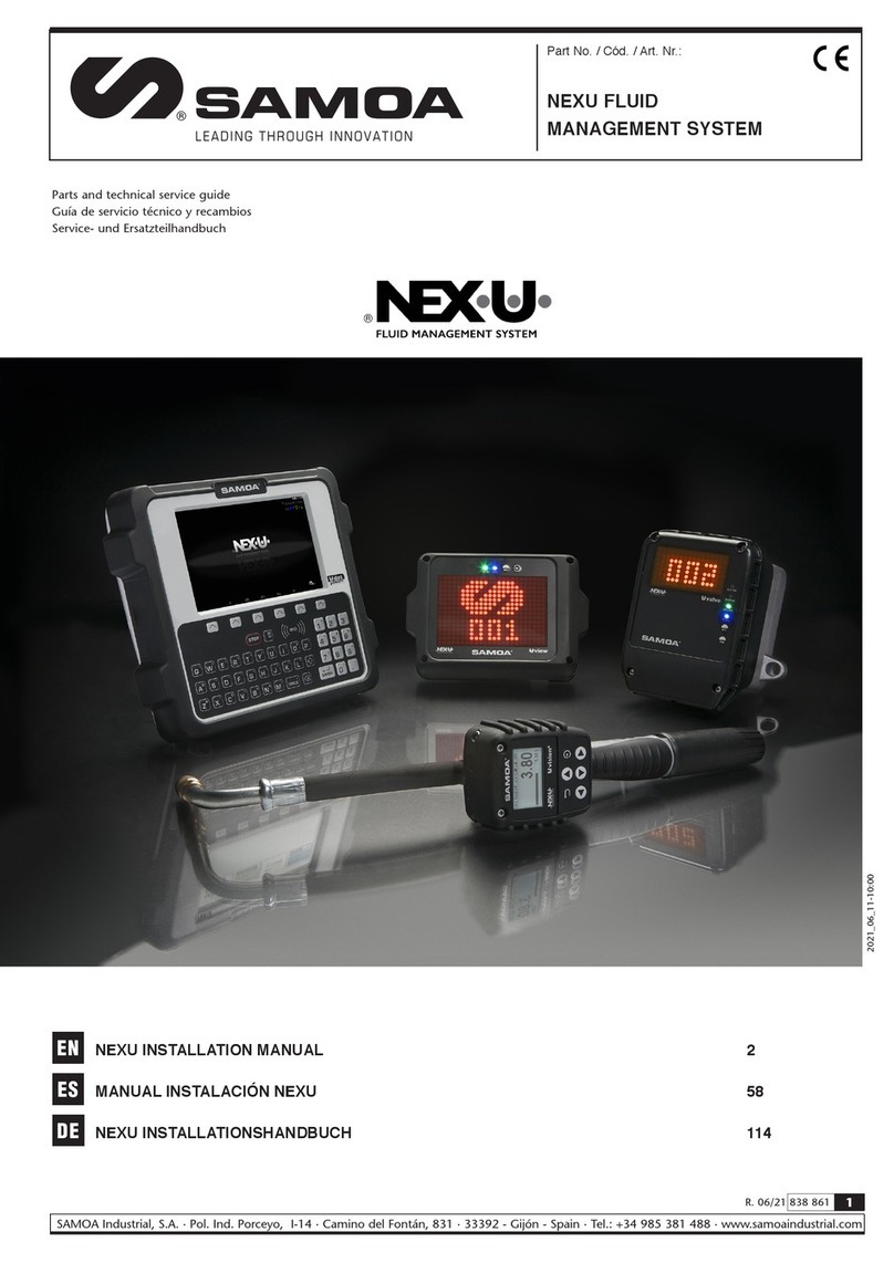
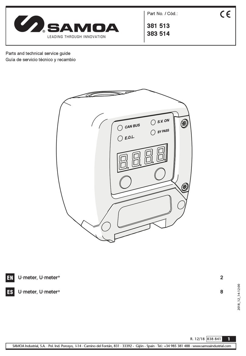
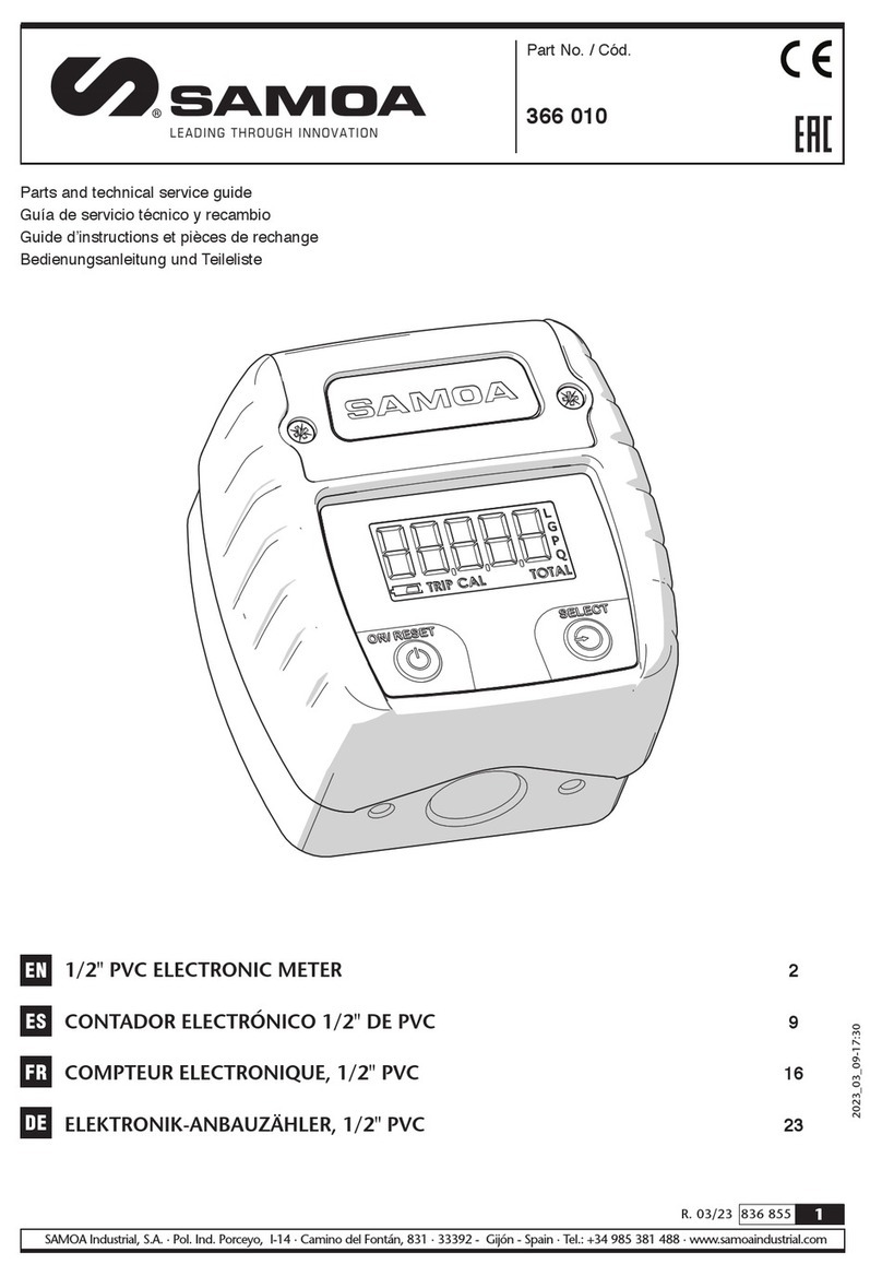
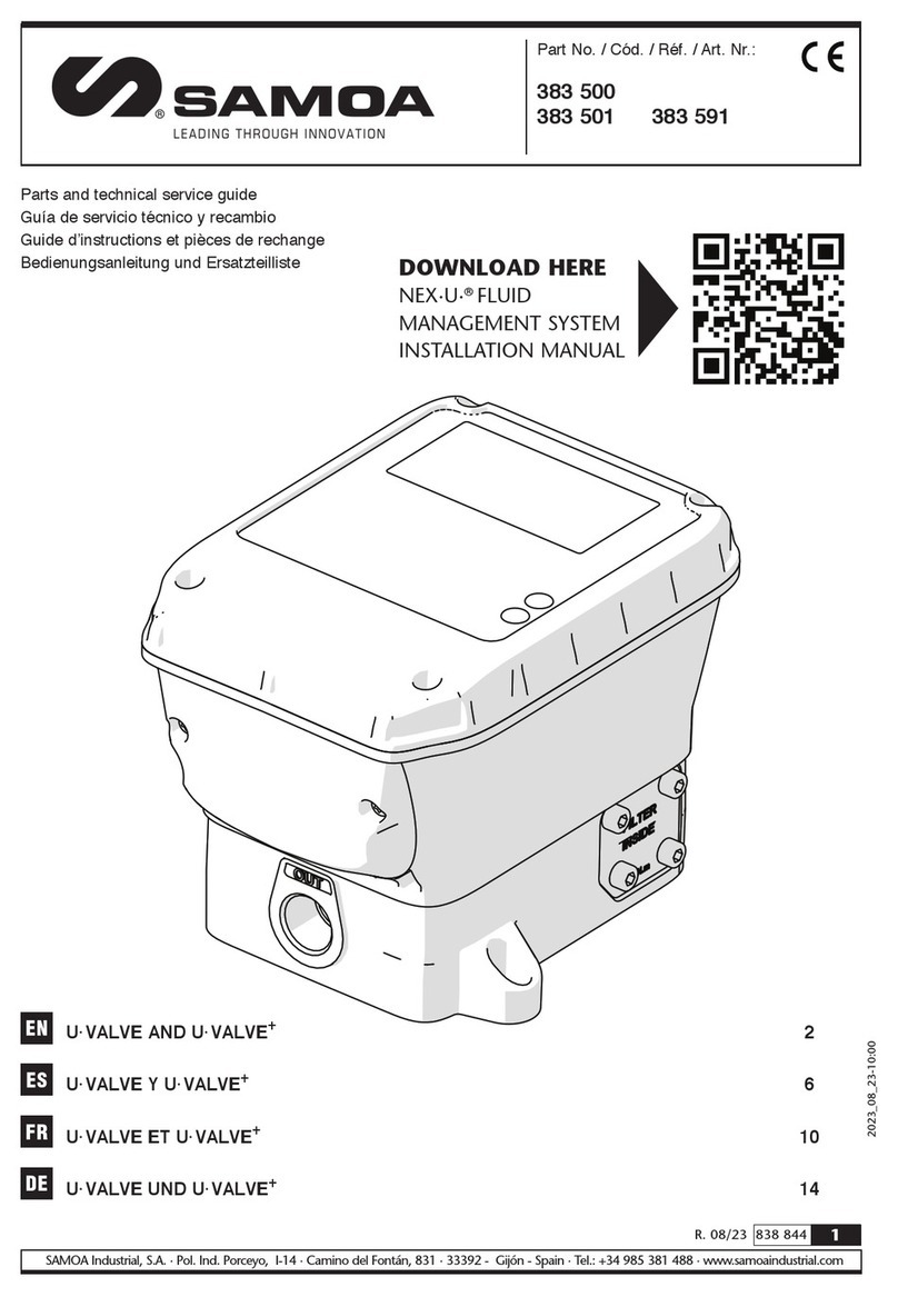
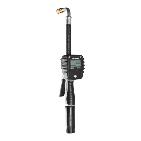
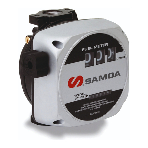
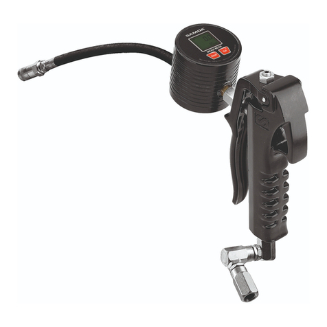
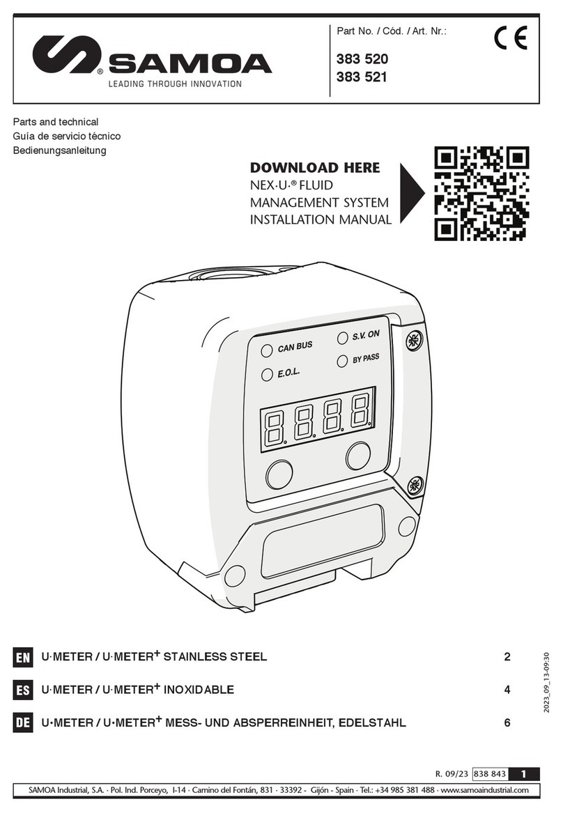
Samoa 383 401 Operating manual

1
R. 06/23 838 856
SAMOA Industrial, S.A. · Pol. Ind. Porceyo, I-14 · Camino del Fontán, 831 · 33392 - Gijón - Spain · Tel.: +34 985 381 488 · www.samoaindustrial.com
2023_06_09-09:30
Part No. / Cód. / Réf. / Art. Nr.:
383 401
U·VISION+CONTROL METER 2
CONTADOR DE CONTROL U·VISION+9
COMPTEUR DE CONTRÔLE U·VISION+16
U·VISION+ KONTROLLMESSGERÄT 23
EN
ES
ES
ES
Parts and technical service guide
Guía de servicio técnico y recambios
Guide d’instructions et pièces de rechange
Bedienungsanleitung und Teileliste

2838 856 R. 06/23
SAMOA Industrial, S.A. · Pol. Ind. Porceyo, I-14 · Camino del Fontán, 831 · 33392 - Gijón - Spain · Tel.: +34 985 381 488 · www.samoaindustrial.com
EN
2023_06_09-09:30
WARNINGS AND CAUTIONS
Product pictures and specifications are subject to change without prior notice.
The English version is a translation of the original document in Spanish. In case of a discrepancy, the original
will prevail.
EQUIPMENT MISUSE
• This equipment is for professional use only. Read all instruction manuals, tags, and labels before
operating the device.
• The device U·vision+is only compatible with the SAMOA oil control gun and fluid handle provided
with outlet flange. In case of doubt or further detailed information, please contact your sales
representative.
• This device cannot operate by itself and is intented to operate with a U·meter+, U·valve or U·count
device.
• In order to operate properly a previous configuration is needed. Consult the configuration chapter.
• Use the device only for its intended purpose
• This device has not been approved for being used in commercial transactions.
• Do not tamper the device.
• Any unauthorised modification to the equipment, misuse, improper maintenance or identification
label removal may void the warranty.
• It is mandatory to respect the polarity of batteries and follow its order of placement as indicated in
the batteries cover.
• Do not mix different battery brands.
• Do not mix new and used batteries.
SAFETY MEASURES
• If a leakage is detected in the batteries protect your eyes and skin. Cover the batteries housing with a
cloth before opening it to avoid that acid get sprayed onto your skin or eyes. If acid should spray into
your eyes, rinse immediately with clear water for several minutes. Consult a doctor immediately
afterwards.
INFORMATION ABOUT WASTES
The previous symbol means that according to local laws and regulations your product and/or its battery must
be disposed of separately from household waste. When this product reaches its end of life, take it to a
collection point designated by local authorities. The separate collection and recycling of your product and/or
its battery at the time of disposal will help conserve natural resources and ensure that it is recycled in a manner
that protects human health and the environment.

3
R. 06/23 838 856
SAMOA Industrial, S.A. · Pol. Ind. Porceyo, I-14 · Camino del Fontán, 831 · 33392 - Gijón - Spain · Tel.: +34 985 381 488 · www.samoaindustrial.com
EN
2023_06_09-09:30
Follow the next procedure in order to install the U·Vision+
device on a control gun:
1. Mount the extension outlet (1) if it is not
already attached.
2. In the case that the control gun has the plastic cover (2)
mounted, remove it by means of a screwdriver or
similar tool. The cover is pressure mounted, it should be
easily removed.
If the flange cover is mounted, remove it as well.
ASSEMBLY
123
4
3. Slide the U·Vision+device (3) through the extension
outlet (1) untill it remains properly fitted onto the flange.
4. Two kits (4) of nut, bolt and washer are supplied with
the U·vision+device to attach the unit to the flange as
indicated in the figure. In the case of the control gun for
dispensing oil use the kit with the M5x25 mm screws
and in the case of the fluid handle use the kit with the
M5x30 mm screws.
BATTERIES INSTALLATION AND REPLACEMENT
NOTE: The U·Vision+device is supplied without the batteries
installed, follow the next steps for proper installation.
1. Loosen the screws (1) with a T15 torx tool and remove
the battery cover (2).
2. Install the supplied batteries (3) checking the polarity as
indicated in the cover (4).
3. Put back the cover (2) and tighten the screws (1).
WARNING: To ensure battery compartment
watertightness, make sure that the battery cover is
properly placed and the screws tightened.
!
Fig. 5
1
2
Fig. 6
3
2
Fig. 7
4

4838 856 R. 06/23
SAMOA Industrial, S.A. · Pol. Ind. Porceyo, I-14 · Camino del Fontán, 831 · 33392 - Gijón - Spain · Tel.: +34 985 381 488 · www.samoaindustrial.com
EN
2023_06_09-09:30
001
The U·vision+can be paired with a U·meter+, U·valve or
U·count device.
Press Power button (Fig. 1) during a short time. In the left
bottom part of the screen, you will see the current
U·vision+firmware version.
Fig. 1 Fig. 2
001
CONNECTING...
U vision+
SAMOA
FW 1.04
Then the U·vision+will try to connect and will show the
connecting screen (Fig. 2). This screen will disappear after
a few seconds if the U·vision+has already been configured,
but if it has not been paired then the message will stay on
screen waiting for configuration.
BUTTONS FUNCTIONS
CONFIGURATION
1. Starting from the connecting screen (Fig. 2) press the
Power and Back button at the same time button until
U·vision+shows “SETUP” (Fig. 3) on the screen. Release
the buttons.
2. Then, the configuration screen is shown automatically
(Fig. 4). The U·vision+is now waiting for you to enter the
reel number you wish to associate.
3. To select the reel you can use the Up and Down buttons,
and press the Power button when the hose reel number
is correct.
4. Once the reel number has been set, the display shows that
the configuration has been accepted and the gun restarts
(Fig. 5). Depending on U·track configuration, the screen
will show “Normal Mode” or “Updating Work Orders”.
Fig. 3 Fig. 4
Fig. 5 Fig. 6
NOTE: make sure that the U·meter+, U·valve or U·count device is powered on before pairing the U·Vision+.
Follow the below instructions to pair your U·Vision+:
001
READY!
✓
PRODUCT
001
001 001
OK!
RESTARTING...
HOSE NB.:
SETUP
?[ 1]
Back/Cancel
Power/Select
Navigation keys (Up/Down)
Navigation keys (Left/Right)
PAIRING THE U·VISION+WITH A FLUID MANAGEMENT DEVICE

5
R. 06/23 838 856
SAMOA Industrial, S.A. · Pol. Ind. Porceyo, I-14 · Camino del Fontán, 831 · 33392 - Gijón - Spain · Tel.: +34 985 381 488 · www.samoaindustrial.com
EN
2023_06_09-09:30
WARNING: this devices only works with Uvalve/Uvalve with firmware versions 1.14 or higher. If you try to connect
U·vision+with a device with a lower version, the U·vision+will show you a warning message (Fig. 1).
!
Fig. 1
009 009
ERROR: NO MODE UVALVE VERS. <1.14
ERROR ERROR
PRODUCT
USING YOUR U·VISION+
If the U·vision+has been properly configured, a short
pressed on the Power button starts the device.
If you have any problem with the device is possible to
restart it by pressing Power button during 5 seconds.
The functionality of the U·vision+is totally related to
U·track software, because it is necessary to configure it,
choosing at least one of the two working modes: NORMAL
MODE or PRESET MODE.
Fig. 2
Fig. 3
This configuration can be made during first devices
configuration (Fig. 2) or anytime after installation in the
U·track DEVICES menu (Fig. 3).
When a transaction is launched in the management system
then the screen shows the transaction mode (Fig. 14 - Pag.
7) in which it can be seen the preselected amount (5).
This mode is the default mode (Fig. 4). Fig. 4
Fig. 5
NORMAL MODE
Fig. 6
003
NORMAL MODE
003
ENTER USER PIN
0
?
010
USER ERROR!!
ERROR
1. Using the different arrows, the operator must enter the
USER PIN, and press the Power button (top right) to
confirm (Fig. 5).
2. Enter the WORK ORDER and press the Power button
to confirm.
3. Finally, enter the AMOUNT and press the Power button to
send all information to U·track software to be verified.
If there is a problem during communication or during
verification, the U·vision+displays warning messages that
define the real problem: USER ERROR (Fig. 6), ORDER
ERROR, QUANTITY ERROR OR COMMUNICATION ERROR
(TRY IT AGAIN).

6838 856 R. 06/23
SAMOA Industrial, S.A. · Pol. Ind. Porceyo, I-14 · Camino del Fontán, 831 · 33392 - Gijón - Spain · Tel.: +34 985 381 488 · www.samoaindustrial.com
EN
2023_06_09-09:30
Fig. 7
Fig. 8
This mode is based on predefined work orders that must be
defined in U·track (Fig. 7).
Each work order will be related to a specific product,
If this mode is correctly defined, when the U·vision+is
awakened, it will try to update the work orders (Fig. 8).
If there are no work orders available (Fig. 9), it displays a
warning message, otherwise, if there are work orders
defined for this dispensing point, U·vision+allows entering
the user’s pin (Fig. 10).
In this mode, the system verifies step by step, first the USER;
if the user exists, the U·vision+displays the list of associated
work orders (Fig. 11). It is possible to choose the required
In both modes, the Back button allows you to cancel the transaction in progress.
PRESET MODE
Fig. 9 Fig. 10
Fig. 11 Fig. 12 Fig. 13
010
UPDATING OTS...
010
ERROR: NO OT RECEIVED
ERROR
003
ENTER USER PIN ?
1
010
SELECT JOB
1-1
ABCDEFGH
010
1.00 L
0.00
010
WAITING TRANSACTION
wo ?
wo ?
wo ?
wo ?
defining the quantity to be dispensed and the number of
repetitions that this order can execute.
work order and after the relevant verification (Fig. 12) the
transaction starts (Fig. 13) with the associated amount in
the U·track.
USING YOUR U·VISION+

7
R. 06/23 838 856
SAMOA Industrial, S.A. · Pol. Ind. Porceyo, I-14 · Camino del Fontán, 831 · 33392 - Gijón - Spain · Tel.: +34 985 381 488 · www.samoaindustrial.com
EN
2023_06_09-09:30
USING YOUR U·VISION+
TRANSACTION SCREEN
Once that the transaction is finished the screen shows for
a few seconds the amount dispensed (Fig. 16).
After that, depending on the monitoring system setup, the
topping screen (Fig. 17) is shown for a certain amount of
time previously preconfigured in the system. During this
period of time it is possible to make the topping from a
keypad. Once that the topping time limit is reached the
screen returns to the “ready for use mode”.
Fig. 14
010
50.00 L
0.00
PRODUCT
2 43
5
1
Fig. 15
010
50.00 L
35.80
PRODUCT
6
7
Fig. 16
001
50.00 L
50.0
PRODUCT
Fig. 17
001
TOP?
PRODUCT
When the trigger of the control valve gun is pulled the fluid
amount being dispensed (6) is displayed. The solenoid valve
open indicator (7) appears on the screen as long as the
U·meter+, U·valve or U·count solenoid valve is open.
BYPASS MODE
The by-pass mode can be activated from a keypad by
means of a key. When this mode is on it is shown on the
screen the information indicated in Fig. 18.
The open solenoid valve indicator (7) is shown on the
screen and the fluid can be dispensed. The quantity
displayed on the screen (8) indicates the total quantity of
fluid dispensed by the unit since it has been switched to
bypass mode (“TOTAL” meter).
Under these mode, a “TRIP” meter is available in order to
simplify the execution of individual dispenses. To do this,
just press and hold the “power” button until the displayed
quantity changes to zero (9). From now on, the dispensed
volume will increase from zero (“TRIP” meter). The “total”
meter will now be displayed on the bottom right corner of
the screen (10), next to the units.
WARNING: In by-pass mode the amount of fluid
dispensed is not registered in the monitoring system.
Fig. 18
001
L
PRODUCT
Fig. 19
001
10.00 L
PRODUCT
0.00
0.00
>>BYPASS<<
>>BYPASS<<
7
8
9
10

8838 856 R. 06/23
SAMOA Industrial, S.A. · Pol. Ind. Porceyo, I-14 · Camino del Fontán, 831 · 33392 - Gijón - Spain · Tel.: +34 985 381 488 · www.samoaindustrial.com
EN
2023_06_09-09:30
TECHNICAL SPECIFICATIONS
Unit compatibility SAMOA 1/2” oil control gun
SAMOA fluid handle
Batteries 4 x AA / LR6
Connectivity Bluetooth®LE
Temperature operation
range -10 ºC to 60 ºC
(14 ºF to 140 ºF)
Weight 420 g (0.92 lb)
Display Dot matrix 128x64 with
backlight
This device complies with Part 15 of the FCC Rules.
Operation is subject to the following two conditions:
(1) This device may not cause harmful interference.
(2) This device must accept any interference received,
including interference That may cause
undesired operation.
TROUBLESHOOTING
Symptom Possible cause Solution
Lack of connection. Unit not configured. Consult pairing instructions.
The screen does not turn on. Wrong batteries assembly. Check batteries polarity.
Batteries run out of energy. Replace batteries.
The unit is configured but it does
not work. Wrong pairing. Check that the unit is paired with the
correct hose reel.

9
R. 06/23 838 856
SAMOA Industrial, S.A. · Pol. Ind. Porceyo, I-14 · Camino del Fontán, 831 · 33392 - Gijón - Spain · Tel.: +34 985 381 488 · www.samoaindustrial.com
EN
2023_06_09-09:30
ES
ADVERTENCIAS Y PRECAUCIONES
Las imágenes y especificaciones de los productos están sujetas a cambios sin previo aviso.
Documento original en español.
USO INDEBIDO DEL EQUIPO
• Este equipo es sólo para uso profesional. Lea atentamente el manual de instrucciones y sus
advertencias antes de empezar a operar con el equipo.
• El dispositivo U·vision+sólo es compatible con la pistola de control de aceite y pistola de fluidos
SAMOA provistas ambas de brida de salida. En caso de duda o para obtener información más
detallada, póngase en contacto con su representante de ventas.
• Este dispositivo no puede funcionar por sí sola y está pensada para funcionar con un dispositivo
U·meter+, U·valve o U·count.
• Para su correcto funcionamiento es necesaria una configuración previa. Consulte el capítulo de
configuración.
• Utilice el equipo sólo para el uso para el cual fue diseñado.
• Este equipo no ha sido aprobado para su empleo en transacciones comerciales.
• No modifique el equipo.
• Cualquier modificación no autorizada del equipo, uso indebido, mantenimiento incorrecto o la
retirada de las etiquetas identificativas puede ser causa de anulación de la garantía.
• Es obligatorio respetar la polaridad de las pilas y seguir su orden de colocación tal y como se indica
en la tapa de las pilas.
• No mezcle distintas marcas de pilas.
• No mezcle pilas nuevas con usadas.
MEDIDAS DE SEGURIDAD
• Si se detecta una fuga en las pilas, protéjase los ojos y la piel. Cubra la carcasa de las pilas con un paño
antes de abrirla para evitar que el ácido salpique su piel u ojos. Si le salpicara ácido en los ojos,
enjuáguelos inmediatamente con agua limpia durante varios minutos. Consulte a un médico
inmediatamente después.
INFORMACIÓN SOBRE DESECHO DE RESIDUOS
El símbolo anterior significa que, de acuerdo con las leyes y normativas locales, su producto y/o su batería
deberán desecharse de manera independiente de los residuos domésticos. Cuando este producto alcance el
final de su vida útil, deberá llevarlo a un punto de recogida designado por las autoridades locales. La recogida
separada y el reciclaje del producto y/o su batería en el momento de su desecho ayudarán a proteger los
recursos naturales y a garantizar su reciclaje de forma que proteja la salud de las personas y el medio ambiente.
10 838 856 R. 06/23
SAMOA Industrial, S.A. · Pol. Ind. Porceyo, I-14 · Camino del Fontán, 831 · 33392 - Gijón - Spain · Tel.: +34 985 381 488 · www.samoaindustrial.com
2023_06_09-09:30
ES
Siga el siguiente procedimiento para instalar el dispositivo
U·vision+en una pistola de control:
1. Instale la extensión (1) en la pistola si no está ya montada.
2. En caso de que la pistola de control tenga montada la
tapa embellecedora (2) retírela con un destornillador o
herramienta similar. La tapa está montada a presión,
debería salir con un ligero esfuerzo.
Si el protector de brida está instalado, retírelo.
3. Deslice el dispositivo U·vision+(3) por la extensión (1)
123
4
hasta que permanece correctamente encajado en su
alojamiento en la brida.
4. Con el dispositivo U·vision+de suministrarán dos kits (4)
de tuerca, tornillo y arandela para fijarlo a la brida de
pistola como se indica en la imagen. En el caso de la
pistola de control para aceite utilice el kit con los
tornillos M5x25 mm y en el caso de la pistola de fluidos
utilice el kit con los tornillos M5x30 mm.
MONTAJE Y SUSTITUCIÓN DE LAS BATERÍAS
ATENCIÓN: El dispositivo U·Vision+se suministra sin las pilas
montadas, siga el siguiente procedimiento para instalarlas:
1. Afloje los tornillos (1) con la llave torx T15 y retire la
tapa (2) del compartimento de baterías.
2. Instale las baterías suministradas (3) respetando la
polaridad (4) indicada en la tapa.
3. Vuelva a poner la tapa (2) y apriete los tornillos (1).
ADVERTENCIA: Para garantizar la estanqueidad
del compartimento de pilas, asegúrese de que la
tapa está correctamente colocada y los tornillos
apretados.
!
Fig. 5
1
2
Fig. 6
3
2
Fig. 7
4
MONTAJE

11
R. 06/23 838 856
SAMOA Industrial, S.A. · Pol. Ind. Porceyo, I-14 · Camino del Fontán, 831 · 33392 - Gijón - Spain · Tel.: +34 985 381 488 · www.samoaindustrial.com
EN
2023_06_09-09:30
ES
FUNCIONES DE LOS BOTONES
001
El dispositivo U·vision+puede emparejarse con dispositivo
U·meter+, U·valve o U·count.
Presiona durante un breve instante de tiempo el botón de
Encendido (Fig. 1). En la parte inferior izquierda de la
pantalla se muestra la versión de software de la U·vision+.
Fig. 1 Fig. 2
001
CONNECTING...
U vision+
SAMOA
FW 1.04
A continuación, la U·vision+intentará conectarse mostrando
la pantalla de intento de conexión (Fig. 2). Si la U·vision+ ya
ha sido configurada esta pantalla desaparecerá tras un
breve instante, pero si no ha sido emparejada permanecerá
fija a la espera de su configuración.
CONFIGURACIÓN
1. Desde la pantalla de conexión (Fig. 2) presione a la vez los
botones de Encendido y de Atrás hasta que la U·vision+
muestre “SETUP” (Fig. 3) en la pantalla. Suelte los botones.
2. A continuación, se muestra automáticamente la pantalla
de configuración (Fig. 4). La U·vision+queda a la espera de
introducir el número de enrollador que desea asociar.
3. Para seleccionar el enrollador puede utilizar los botones de
Arriba y Abajo, y presionar el botón de Encendido cuando
el número de enrollador de manguera sea el correcto.
4. Una vez fijado el número de enrollador se muestra en la
pantalla la aceptación de la configuración y la pistola se
reinicia (Fig. 5). Dependiendo de la configuración del
U·track, la pantalla mostrará “modo normal” o
“actualizando órdenes de trabajo”.
Fig. 3
Fig. 4
Fig. 5 Fig. 6
NOTA: Asegúrese de que el dispositivo U·meter+, U·valve o U·count está encendida antes de emparejar la U·vision+.
Para emparejar la U·vision+siga el siguiente procedimiento:
001
READY!
✓
PRODUCT
001
001
001
OK!
RESTARTING...
HOSE NB.:
SETUP ?[ 1]
Atrás/Cancelar
Encendido/Select
Teclas de navegación (Arriba/Abajo)
Teclas de navegación (Izquierda/Derecha)
EMPAREJAMIENTO DE LA U·VISION+CON UN DISPOSITIVO DE CONTROL DE FLUIDO

12 838 856 R. 06/23
SAMOA Industrial, S.A. · Pol. Ind. Porceyo, I-14 · Camino del Fontán, 831 · 33392 - Gijón - Spain · Tel.: +34 985 381 488 · www.samoaindustrial.com
2023_06_09-09:30
ES
ADVERTENCIA: estos dispositivos solo funcionan con U·valve/U·valve+con versiones de firmware 1.14 o
superiores. Si intentas conectar la U·vision+con un dispositivo con una versión inferior, la U·vision+mostrará un
mensaje de advertencia (Fig. 1).
!
Fig. 1
009 009
ERROR: NO MODE UVALVE VERS. <1.14
ERROR ERROR
PRODUCT
CONFIGURACIÓN
Si la U·vision+ha sido configurada correctamente, pulsa el
botón de Encendido para ponerlo en marcha.
Si tiene algún problema con el dispositivo es posible reiniciarlo
pulsando el botón de Encendido durante 5 segundos.
La funcionalidad de la U·vision+está totalmente relacionada
con el software U·track, ya que es necesario configurarlo,
eligiendo al menos uno de los dos modos de trabajo:
Fig. 2
Fig. 3
MODO NORMAL O MODO PRESET.
Esta configuración puede realizarse durante la primera
configuración de los dispositivos (Fig. 2) o en cualquier
momento después de la instalación en el menú
DISPOSITIVOS del U·track (Fig. 3).
Cuando se lanza una transacción en el sistema de gestión,
la pantalla muestra el modo transacción (Fig. 14-Pág. 14)
en el que se puede ver la cantidad preseleccionada (5).
Este modo es el modo por defecto (Fig. 4). Fig. 4
Fig. 5
MODO NORMAL
Fig. 6
003
NORMAL MODE
003
ENTER USER PIN
0
?
010
USER ERROR!!
ERROR
1. Utilizando las diferentes flechas, el operador debe introducir
el PIN DE USUARIO, y pulsar el botón de Encendido para
confirmar (Fig. 5).
2. Introduzca la ORDEN DE TRABAJO y pulse el botón de
Encendido para confirmar.
3. Por último, introduzca la CANTIDAD y pulse el botón de
Encendido para enviar toda la información al software
U·track para su verificación.
Si se produce algún problema durante la comunicación o
durante la verificación, la U·vision+muestra mensajes de
advertencia que definen el problema real: ERROR DE
USUARIO (Fig. 6), ERROR DE PEDIDO, ERROR DE
CANTIDAD O ERROR DE COMUNICACIÓN (INTÉNTELO
DE NUEVO).

13
R. 06/23 838 856
SAMOA Industrial, S.A. · Pol. Ind. Porceyo, I-14 · Camino del Fontán, 831 · 33392 - Gijón - Spain · Tel.: +34 985 381 488 · www.samoaindustrial.com
EN
2023_06_09-09:30
ES
Fig. 7
Fig. 8
Este modo se basa en órdenes de trabajo predefinidas que
deben definirse en el U·track (Fig. 7).
Cada orden de trabajo estará relacionada con un producto
Si este modo está correctamente definido, cuando la
U·vision+se despierte, intentará actualizar las órdenes de
trabajo (Fig. 8).
Si no hay órdenes de trabajo disponibles (Fig. 9), mostrará
un mensaje de advertencia, de lo contrario, si hay órdenes
de trabajo definidas para este punto de dispensado, la
U·vision+permite introducir el PIN DE USUARIO (Fig. 10)
En este modo, el sistema verifica paso a paso, primero el
USUARIO; si el usuario existe, U·vision+muestra la lista de
órdenes de trabajo asociadas (Fig. 11).
En ambos modos, el botón de Atrás te permite cancelar la transacción en progreso.
MODO PRESET
Fig. 9 Fig. 10
Fig. 11 Fig. 12 Fig. 13
010
UPDATING OTS...
010
ERROR: NO OT RECEIVED
ERROR
003
ENTER USER PIN ?
1
010
SELECT JOB
1-1
ABCDEFGH
010
1.00 L
0.00
010
WAITING TRANSACTION
wo ?
wo ?
wo ?
wo ?
específico, definiendo la cantidad a dispensar y el número
de repeticiones que esta orden puede ejecutar.
Es posible elegir la orden de trabajo deseada y tras la
verificación pertinente (Fig. 12) se inicia la transacción (Fig.
13) con la cantidad asociada en el U·track.
CONFIGURACIÓN

14 838 856 R. 06/23
SAMOA Industrial, S.A. · Pol. Ind. Porceyo, I-14 · Camino del Fontán, 831 · 33392 - Gijón - Spain · Tel.: +34 985 381 488 · www.samoaindustrial.com
2023_06_09-09:30
ES
CONFIGURACIÓN
PANTALLA DE TRANSACCIÓN
Una vez finalizada la transacción, la pantalla muestra
durante unos segundos la cantidad dispensada (Fig. 16).
A continuación, dependiendo de la configuración del
sistema de monitorización, se muestra la pantalla de
topping (Fig. 17) durante un tiempo previamente
preconfigurado en el sistema. Durante este periodo de
tiempo es posible realizar el topping desde un teclado. Una
vez alcanzado el límite de tiempo, la pantalla vuelve al
“modo listo para su uso”.
Fig. 14
010
50.00 L
0.00
PRODUCT
2 43
5
1
Fig. 15
010
50.00 L
35.80
PRODUCT
6
7
Fig. 16
001
50.00 L
50.0
PRODUCT
Fig. 17
001
TOP?
PRODUCT
Cuando se aprieta el gatillo de la pistola de control, se
muestra la cantidad de fluido que está siendo dispensada (6).
El indicador de electroválvula abierta (7) aparece en la
pantalla mientras la electroválvula de la U·meter+, U·valve o
U·count esté abierta.
BYPASS MODE
El modo by-pass puede activarse desde un teclado mediante
una tecla. Cuando este modo está activado se muestra en
la pantalla la información indicada en la Fig. 18.
El indicador de electroválvula abierta (7) se muestra en la
pantalla y se puede dispensar el fluido. La cantidad
mostrada en la pantalla (8) indica la cantidad total de
fluido dispensado por el dispositivo desde que se ha
cambiado al modo bypass (contador “TOTAL”).
En este modo, se dispone de un contador de “disparo”
para simplificar la ejecución de transacciones individuales.
Para ello, basta con mantener pulsado el botón de
Encendido hasta que la cantidad mostrada cambie a cero
(9). A partir de este momento, el volumen dispensado
aumentará a partir de cero (contador “TRIP”). El contador
“TOTAL” se mostrará ahora en la esquina inferior derecha
de la pantalla (10), junto a las unidades.
ADVERTENCIA: En el modo bypass la cantidad de fluido
dispensado no se registra en el sistema de monitorización.
Fig. 18
001
L
PRODUCT
Fig. 19
001
10.00 L
PRODUCT
0.00
0.00
>>BYPASS<<
>>BYPASS<<
7
8
9
10

15
R. 06/23 838 856
SAMOA Industrial, S.A. · Pol. Ind. Porceyo, I-14 · Camino del Fontán, 831 · 33392 - Gijón - Spain · Tel.: +34 985 381 488 · www.samoaindustrial.com
EN
2023_06_09-09:30
ES
CARACTERÍSTICAS TÉCNICAS
Compatibilidad Pistola de aceite ½” SAMOA
Pistola de fluidos SAMOA
Alimentación 4 x AA / LR6
Conectividad Bluetooth®LE
Temperatura
de operación -10 ºC a 60 ºC
(14 ºF a 140 ºF)
Peso 420 g (0.92 lb)
Pantalla Matriz de puntos 128x64
con retroiluminación
Este dispositivo cumple la Parte 15 de las normas de la FCC.
Su funcionamiento está sujeto a las dos
siguientes condiciones:
(1) Este dispositivo no puede causar interferencias perjudiciales.
(2) Este dispositivo debe aceptar cualquier interferencia
recibida, incluidas las interferencias que puedan causar un
funcionamiento no deseado.
DIAGNÓSTICO Y SOLUCIÓN DE PROBLEMAS
Síntoma Posible causa Solución
Sin conexión. Dispositivo no configurado. Realice el procedimiento
de emparejamiento.
La pantalla no enciende. Montaje incorrecto de polaridad de pilas. Verificar montaje de pilas.
Pilas agotadas. Sustituir pilas.
El dispositivo está configurado,
pero no cuenta Emparejamiento incorrecto. Verifique que el dispositivo está
asociado al enrollador correcto.

16 838 856 R. 06/23
SAMOA Industrial, S.A. · Pol. Ind. Porceyo, I-14 · Camino del Fontán, 831 · 33392 - Gijón - Spain · Tel.: +34 985 381 488 · www.samoaindustrial.com
2023_06_09-09:30
FR
AVERTISSEMENTS ET MISES EN GARDE
Les images et les spécifications des produits sont susceptibles d’être modifiées sans préavis.
La version anglaise est une traduction du document original en espagnol. En cas de divergence,
l’original prévaudra.
MAUVAISE UTILISATION DE L’ÉQUIPEMENT
• Cet équipement est réservé à un usage professionnel. Lisez tous les manuels d’instructions, étiquettes
et étiquettes avant d’utiliser l’appareil.
• L’appareil U·vision+n’est compatible qu’avec le pistolet de contrôle d’huile SAMOA et la poignée
produit munie d’une bride de sortie. En cas de doute ou d’informations plus détaillées, veuillez
contacter votre représentant commercial.
• Cet appareil ne peut pas fonctionner seul et est conçu pour fonctionner avec un appareil U·meter+,
U·value ou U·count.
• Pour fonctionner correctement, une configuration préalable est nécessaire. Consulter le chapitre
configuration.
• Utilisez l’appareil uniquement aux fins pour lesquelles il a été conçu.
• Cet appareil n’a pas été approuvé pour être utilisé dans des transactions commerciales.
• Ne pas altérer l’appareil.
• Toute modification non autorisée de l’équipement, mauvaise utilisation, entretien inapproprié ou
retrait de l’étiquette d’identification peut annuler la garantie.
• Il est obligatoire de respecter la polarité des piles et de suivre son ordre de placement comme indiqué
dans le couvercle des piles.
• Ne mélangez pas différentes marques de piles.
• Ne mélangez pas des piles neuves avec des anciennes.
MESURES DE SÉCURITÉ
• Si une fuite est détectée dans les piles, protégez vos yeux et votre peau. Couvrez le boîtier des piles
avec un chiffon avant de l’ouvrir pour éviter que de l’acide ne soit pulvérisé sur votre peau ou vos
yeux. En cas de projection d’acide dans les yeux, rincez immédiatement à l’eau claire pendant
plusieurs minutes. Consulter un médecin immédiatement.
INFORMATIONS SUR LES DÉCHETS
Le symbole précédent signifie que, conformément aux lois et réglementations locales, votre produit et/ou sa
batterie doivent être éliminés séparément des ordures ménagères. Lorsque ce produit arrive en fin de vie,
apportez-le à un point de collecte désigné par les autorités locales. La collecte et le recyclage séparés de votre
produit et/ou de sa batterie au moment de sa mise au rebut contribueront à préserver les ressources naturelles
et à garantir qu’il est recyclé d’une manière qui protège la santé humaine et l’environnement.

17
R. 06/23 838 856
SAMOA Industrial, S.A. · Pol. Ind. Porceyo, I-14 · Camino del Fontán, 831 · 33392 - Gijón - Spain · Tel.: +34 985 381 488 · www.samoaindustrial.com
EN
2023_06_09-09:30
FR
Suivez la procédure suivante pour installer le dispositif
U·Vision+sur un pistolet de contrôle:
1. Montez la prise d’extension (1) si elle n’est pas déjà fixée.
2. Dans le cas où le pistolet de contrôle a le couvercle en
plastique (2) monté, retirez-le à l’aide d’un tournevis ou
d’un outil similaire. Le couvercle est monté par pression,
il doit être facilement retiré. Si le couvercle de bride est
monté, retirez-le également.
3. Faites glisser l’appareil U·Vision+ (3) à travers la sortie
123
4
d’extension (1) jusqu’à ce qu’il reste correctement fixé
sur la bride.
4. Deux kits (4) d’écrou, de boulon et de rondelle sont
fournis avec le dispositif U·vision+ pour fixer l’unité à la
bride comme indiqué sur la figure. Dans le cas du pistolet
de contrôle pour la distribution d’huile, utiliser le kit avec
les vis M5x25 mm et dans le cas de la poignée à fluide,
utiliser le kit avec les vis M5x30 mm.
INSTALLATION ET REMPLACEMENT DES PILES
NOTE: L’appareil U·Vision+est fourni sans les piles installées,
suivez les étapes suivantes pour une installation correcte:
1. Desserrez les vis (1) avec un outil T15 et retirez le
couvercle de la batterie (2).
2. Installez les piles fournies (3) en vérifiant la polarité
comme indiqué sur le couvercle (4).
3. Remettre le couvercle (2) et serrer les vis (1).
AVERTISSEMENT: Pour assurer l’étanchéité du
compartiment à piles, assurez-vous que le
couvercle de la pile est correctement placé et que
les vis sont bien serrées.
!
Fig. 5
1
2
Fig. 6
3
2
Fig. 7
4
ASSEMBLAGE

18 838 856 R. 06/23
SAMOA Industrial, S.A. · Pol. Ind. Porceyo, I-14 · Camino del Fontán, 831 · 33392 - Gijón - Spain · Tel.: +34 985 381 488 · www.samoaindustrial.com
2023_06_09-09:30
FR
FONCTIONS DES BOUTONS
001
Le U·vision+peut être couplé avec un appareil U·meter+,
U·valve ou U·count.
Appuyez brièvement sur le bouton d’alimentation (Fig. 1).
Dans la partie inférieure gauche de l’écran, vous verrez la
version actuelle du micrologiciel U·vision+.
Fig. 1 Fig. 2
001
CONNECTING...
U vision+
SAMOA
FW 1.04
Ensuite, l’U·vision+essaiera de se connecter et affichera
l’écran de connexion (Fig. 2). Cet écran disparaîtra après
quelques secondes si le U·vision+a déjà été configuré, mais
s’il n’a pas été apparié alors le message restera à l’écran en
attendant la configuration.
CONFIGURATION
1. Àpartirde l’écrandeconnexion(Fig. 2),appuyezsimultanément
sur les boutons Power et Back jusqu’à ce que U·vision+ affiche
« SETUP » (Fig. 3) à l’écran. Relâchez les boutons.
2. Ensuite, l’écran de configuration s’affiche automatiquement
(Fig. 4). L’U·vision+ attend maintenant que vous saisissiez
le numéro de bobine que vous souhaitez associer.
3. Pour sélectionner l’enrouleur, vous pouvez utiliser les
boutons Haut et Bas, et appuyer sur le bouton
d’alimentation lorsque le numéro d’enrouleur est correct.
4. Une fois le numéro de bobine défini, l’écran indique que
la configuration est acceptée et le pistolet redémarre (Fig.
5). Selon la configuration U·track, l’écran affichera
“Normal Mode” ou “Updating Work Orders”.
Fig. 3 Fig. 4
Fig. 5 Fig. 6
NOTE: Assurez-vous que l’appareil U·meter+, U·valve ou U·count est sous tension avant de coupler l’U·Vision+. Suivez
les instructions ci-dessous pour coupler votre U·Vision+:
001
READY!
✓
PRODUCT
001
001
001
OK!
RESTARTING...
HOSE NB.:
SETUP
?[ 1]
Retour/Annuler
Alimentation/Sélection
Touches de navigation (Haut/Bas)
Touches de navigation (Gauche/Droite)
ASSOCIATION DU U·VISION+AVEC UN DISPOSITIF DE GESTION DES FLUIDES

19
R. 06/23 838 856
SAMOA Industrial, S.A. · Pol. Ind. Porceyo, I-14 · Camino del Fontán, 831 · 33392 - Gijón - Spain · Tel.: +34 985 381 488 · www.samoaindustrial.com
EN
2023_06_09-09:30
FR
AVERTISSEMENT: cet appareil fonctionne uniquement avec Uvalve/Uvalve avec les versions de firmware 1.14 ou
supérieures. Si vous essayez de connecter U·vision+ avec un appareil avec une version inférieure, U·vision+ vous
montrera un message d’avertissement (Fig. 1).
!
Fig. 1
009 009
ERROR: NO MODE UVALVE VERS. <1.14
ERROR ERROR
PRODUCT
CONFIGURATION
Si l’U·vision+ a été correctement configuré, un appui court
sur le bouton d’alimentation démarre l’appareil.
Si vous rencontrez un problème avec l’appareil, il est
possible de le redémarrer en appuyant sur le bouton
d’alimentation pendant 5 secondes.
La fonctionnalité de U·vision+ est totalement liée au
logiciel U·track, car il est nécessaire de le configurer en
Fig. 2
Fig. 3
choisissant au moins un des deux modes de
fonctionnement: MODE NORMAL ou MODE PRESET.
Cette configuration peut être effectuée lors de la première
configuration des dispositifs (Fig. 2) ou à tout moment
après l’installation dans le menu U·track DEVICES (Fig. 3).
Lorsqu’une transaction est lancée dans le système de
gestion, l’écran affiche le mode de transaction (Fig. 14 - Pag.
7) dans lequel on peut voir le montant présélectionné (5).
Ce mode est le mode par défaut (Fig. 4). Fig. 4
Fig. 5
MODE NORMAL
Fig. 6
003
NORMAL MODE
003
ENTER USER PIN
0
?
010
USER ERROR!!
ERROR
1. À l’aide des différentes flèches, l’opérateur doit entrer le
code PIN UTILISATEUR et appuyer sur le bouton
d’alimentation (en haut à droite) pour confirmer (Fig. 5).
2. Entrez l’ORDRE DE TRAVAIL et appuyez sur le bouton
d’alimentation pour confirmer
3. Enfin, entrez le MONTANT et appuyez sur le bouton
d’alimentation pour envoyer toutes les informations au
logiciel U·track à vérifier.
S’il y a un problème pendant la communication ou pendant
la vérification, l’U·vision+ affiche des messages
d’AVERTISSEMENT qui définissent le vrai problème: ERREUR
UTILISATEUR (Fig. 6), ERREUR DE COMMANDE, ERREUR DE
QUANTITÉ OU ERREUR DE COMMUNICATION (RÉESSAYER).

20 838 856 R. 06/23
SAMOA Industrial, S.A. · Pol. Ind. Porceyo, I-14 · Camino del Fontán, 831 · 33392 - Gijón - Spain · Tel.: +34 985 381 488 · www.samoaindustrial.com
2023_06_09-09:30
FR
Fig. 7
Fig. 8
Ce mode est basé sur des ordres de travail prédéfinis qui
doivent être définis dans U·track (Fig. 7).
Chaque bon de travail sera lié à un produit spécifique, en
Si ce mode est correctement défini, au réveil du U·vision+,
il tentera de mettre à jour les bons de travail (Fig. 8).
S’il n’y a pas de bons de travail disponibles (Fig. 9), il affiche
un message d’avertissement, sinon, s’il y a des bons de
travail définis pour ce point de distribution, U·vision+
permet d’entrer le code PIN de l’utilisateur. (Fig. 10).
Dans ce mode, le système vérifie étape par étape, d’abord
l’UTILISATEUR ; si l’utilisateur existe, le U·vision+ affiche la
liste des bons de travail associés (Fig. 11).
Dans les deux modes, le bouton Retour permet d’annuler la transaction en cours.
MODO PRESET
Fig. 9 Fig. 10
Fig. 11 Fig. 12 Fig. 13
010
UPDATING OTS...
010
ERROR: NO OT RECEIVED
ERROR
003
ENTER USER PIN ?
1
010
SELECT JOB
1-1
ABCDEFGH
010
1.00 L
0.00
010
WAITING TRANSACTION
wo ?
wo ?
wo ?
wo ?
définissant la quantité à distribuer et le nombre de
répétitions que cette commande peut exécuter.
Il est possible de choisir le bon de travail requis et après la
vérification correspondante (Fig. 12) la transaction
commence (Fig. 13) avec le montant associé dans le U·track.
CONFIGURATION
Table of contents
Languages:
Other Samoa Measuring Instrument manuals

Samoa
Samoa 366010 User manual

Samoa
Samoa 383 700 How to use

Samoa
Samoa U-VISION 383 400 Operating manual

Samoa
Samoa NEXU Operating manual

Samoa
Samoa 366760 Operating manual

Samoa
Samoa U-VISION 383 400 How to use

Samoa
Samoa Oval Gear Meter User manual

Samoa
Samoa 381 513 User manual

Samoa
Samoa U.VALVE Operating manual

Samoa
Samoa 411100 User manual
Popular Measuring Instrument manuals by other brands

Tektronix
Tektronix 7L13 instruction manual

HOKUYO AUTOMATIC
HOKUYO AUTOMATIC UHG-08LX instruction manual

Chauvin Arnoux
Chauvin Arnoux C.A 852 user manual

ZHEJIANG FENGDENG ELCTRIC CO.,LTD
ZHEJIANG FENGDENG ELCTRIC CO.,LTD DS5210 Series user manual

Craftsman
Craftsman 320.29939 owner's manual

Dinel
Dinel CLM-36 instruction manual