Incredible Technologies Big Buck Hunter CALL OF THE WILD User manual

© Copyright 2005 Incredible Technologies, Inc. All Rights Reserved.
INSTALLATION AND OPERATION MANUAL
Version 01/05

Big Buck Hunter™ Page 1Version 01/05
© Copyright 2004-2005 Incredible Technologies, Inc. All Rights Reserved. Unauthorized duplication is a violation of applicable law.
All other marks are the properties of their respective owners. All rights reserved.
l
FEATURES
•Up to Four Players can Hunt in Head-To-Head Competition!
•Select from Traditional Play, Hunt Club, Tournament Play Modes
•Improved Hunt Club Play For More Stats and Variety
•Unique New Bonus Only Play Mode
•Over 480 Authentic and Unique 3D Hunting Scenes
•Hunt All Across the US and Canada, Including the New Midwest and Southwest
Regions
•Hunt in Varying Weather Conditions: Sunlight, Rain, Fog and Snow
•Hunt During Different Times of Day: Early Morning, Afternoon and Night
•Hunt Deer, Elk and now Antelope
•Exciting Bonus Rounds Lets you Test your Skill on Doves, Pheasant, Squirrel,
Duck, Skeet, Raccoon, and a Huge Variety of Targets
•Operator Selectable Bloodless and Tagging Modes

Big Buck Hunter™ Page 2Version 01/05
© Copyright 2004-2005 Incredible Technologies, Inc. All Rights Reserved. Unauthorized duplication is a violation of applicable law.
All other marks are the properties of their respective owners. All rights reserved.
FEATURES.......................................................................................................................................................1
DEDICATED CABINETS ........................................................................................................................................ 4
DEDICATED GAME CONTENTS ................................................................................................................................. 4
RECOMMENDED SUPPLIES ...................................................................................................................................... 4
THE CABINET ........................................................................................................................................................ 4
Key Measurements...........................................................................................................................................4
Power Requirements.........................................................................................................................................4
Rifle and Holster Clips.......................................................................................................................................4
Hard Drive ........................................................................................................................................................4
Volume and Test Switches................................................................................................................................4
LED Sign ..........................................................................................................................................................4
Security Bar ......................................................................................................................................................5
Card Reader.....................................................................................................................................................5
Monitor..............................................................................................................................................................5
DIP SWITCH SETTINGS ........................................................................................................................................ 5
BIG BUCK HUNTER COTW PCB CONNECTIONS ................................................................................................ 5
KIT GAME INSTALLATION.................................................................................................................................... 5
KIT PACKAGE CONTENTS........................................................................................................................................ 6
RECOMMENDED TOOLS AND SUPPLIES..................................................................................................................... 6
INSTALLATION PREPARATION ........................................................................................................................... 6
THE CABINET ........................................................................................................................................................ 6
Power Requirements.........................................................................................................................................6
Monitor Requirements.......................................................................................................................................6
Cabinet Selection..............................................................................................................................................7
CONTROL PANEL ................................................................................................................................................... 7
Button Preparation............................................................................................................................................7
Volume and Test Switches................................................................................................................................8
GRAPHIC OVERLAYS .............................................................................................................................................. 8
Control Panel Overlay Installation......................................................................................................................8
Function Labels Overlay Installation..................................................................................................................8
Marquee Installation..........................................................................................................................................8
Cabinet Side Graphics Installation.....................................................................................................................8
RIFLE HOLSTER INSTALLATION ................................................................................................................................ 9
Gun Installation...............................................................................................................................................10
WIRING AND HARDWARE ASSEMBLY ...................................................................................................................... 10
Control Panel Assembly ..................................................................................................................................10
Printed Circuit Board (PCB).............................................................................................................................10
PCB and Hard Drive Installation......................................................................................................................11
Wire Harness..................................................................................................................................................12
Power Supply and Connections.......................................................................................................................12
Instructions for ATX Power Supplies:...............................................................................................................12
SYNC .............................................................................................................................................................13
Coin Doors, Test Switch, and Volume Control Panel .......................................................................................13
Final Check.....................................................................................................................................................13
DIP SWITCH SETTINGS ...................................................................................................................................... 13
CONNECTING THE PHONE LINE........................................................................................................................ 13
NODE CONNECTIONS ........................................................................................................................................ 14
INITIAL POWER-UP ............................................................................................................................................. 14
ITNET OPERATOR REGISTRATION ................................................................................................................... 15

Big Buck Hunter™ Page 3Version 01/05
© Copyright 2004-2005 Incredible Technologies, Inc. All Rights Reserved. Unauthorized duplication is a violation of applicable law.
All other marks are the properties of their respective owners. All rights reserved.
ITNET INSTALLATION PROCEDURE ................................................................................................................. 15
OPERATOR TEST MODE .................................................................................................................................... 16
MAIN MENU......................................................................................................................................................... 16
ITNET COLLECTIONS & AUDITS RESET.......................................................................................................... 16
OPERATOR ADJUSTABLES MENU........................................................................................................................... 17
GAME MODE SELECTION.............................................................................................................................17
COIN DOOR SETTINGS.................................................................................................................................18
SKILL LEVEL ADJUSTMENT..........................................................................................................................18
PLAYER COST SCHEDULE...........................................................................................................................18
VOLUME SETTINGS ......................................................................................................................................18
ATTRACT MODE SOUNDS............................................................................................................................19
VIOLENCE......................................................................................................................................................19
EMAIL REQUEST MENU................................................................................................................................19
COIN PAGE PROMPT TEXT..........................................................................................................................20
RESET OPERATOR ADJUSTABLES .............................................................................................................20
GAME AUDITS MENU............................................................................................................................................ 20
DISPLAY COIN AUDITS .................................................................................................................................20
DISPLAY GAME PURCHASE AUDITS ...........................................................................................................21
DISPLAY REGION AUDITS ............................................................................................................................21
DISPLAY LIFETIME COIN AUDITS ................................................................................................................21
ITNET MENU....................................................................................................................................................... 22
ITNET ADJUSTABLES MENU ........................................................................................................................25
DISABLE\ENABLE TOURNAMENTS ..............................................................................................................26
DISPLAY TIMERS ..........................................................................................................................................27
SYSTEM TESTS MENU .......................................................................................................................................... 28
VIDEO SCREEN TESTS.................................................................................................................................28
SOUND TESTS ..............................................................................................................................................28
SWITCH TESTS .............................................................................................................................................28
SERIAL PORT TESTS ....................................................................................................................................28
COMMUNICATION TESTS.............................................................................................................................29
MOTHERBOARD TESTS................................................................................................................................29
GUN CALIBRATION RESULTS \INPUT TEST...............................................................................................29
GUN FLASH/MONITOR BRIGHTNESS TEST ................................................................................................30
GUN CALIBRATION MENU...................................................................................................................................... 31
MAILBOX............................................................................................................................................................. 31
HIGH SCOREBOARDS MENU.................................................................................................................................. 31
AUTOMATIC STARTUP TEST AND SWITCH TESTS..................................................................................................... 31
JAMMA HARNESS AND GUN CONNECTIONS........................................................................................................... 32
JAMMA Harness Connection ..........................................................................................................................32
Gun Harness Connection................................................................................................................................32
RIFLE PART NUMBERS ......................................................................................................................................... 33
APPENDIX A........................................................................................................................................................ 35
GENERAL TROUBLESHOOTING............................................................................................................................... 35
Video Problems...............................................................................................................................................35
Sound Problems .............................................................................................................................................35
Gun Problems .................................................................................................................................................36
Control Problems ............................................................................................................................................37
Power-Up Problems ........................................................................................................................................37
Miscellaneous Problems .................................................................................................................................37
APPENDIX B........................................................................................................................................................ 38
ITS®/ITNET® ONLINE OVERVIEW.................................................................................................................... 38
ITNET® DEBIT ACCOUNT FORM ..................................................................................................................... 39
ITNET® OPERATOR AGREEMENT FORM ....................................................................................................... 41
ITNET® GAME REGISTRATION FORM ............................................................................................................ 43
APPENDIX C........................................................................................................................................................ 43
APPENDIX C........................................................................................................................................................ 45
INDUSTRY CANADA (IC) NOTICE .................................................................................................................45
FCC Regulation Compliance...........................................................................................................................45
WARNINGS AND NOTICES.............................................................................................................................. 46
CONTACT INFORMATION ....................................................................................................................................... 47

Big Buck Hunter™ Page 4Version 01/05
© Copyright 2004-2005 Incredible Technologies, Inc. All Rights Reserved. Unauthorized duplication is a violation of applicable law.
All other marks are the properties of their respective owners. All rights reserved.
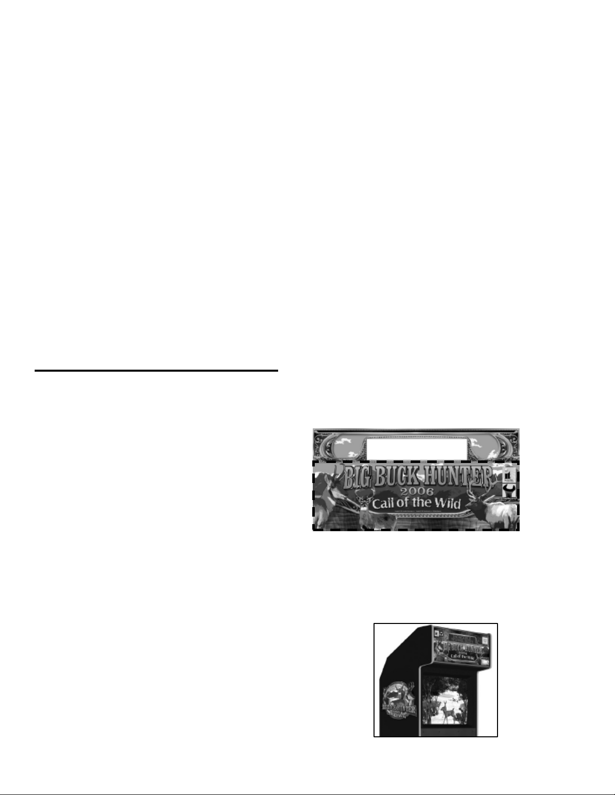
DEDICATED CABINETS
DEDICATED GAME CONTENTS
(1) Big Buck Hunter Call of the Wild
Dedicated Cabinet with LED Sign
(1) Gun Assembly
(1) Big Buck Hunter COTW Manual
(1) Monitor Manual
(1) 50 ft. Telephone Cable
(1) Telephone Line Splitter
RECOMMENDED SUPPLIES
qAnalog telephone connection.
qInexpensive telephone, used to test the line
connection.
THE CABINET
Your Big Buck Hunter Call of the Wild cabinet comes with
the hard drive packed in a padded box inside the cabinet.
Install the hard drive carefully. Make sure all of the
connectors, wires, harnesses and PCB cards are seated
securely in their sockets before applying power.
Key Measurements
•Shipping Dimensions (height x width x depth): 78 x 30
x 37 [inches] 198.12 x 76.2 x 93.98 [centimeters]
•Shipping Weight: 415 [pounds] 188.24 [kilograms]
•Power Supply Specs (input/output voltages, power):
ATX: input 115VAC (8A) 230VAC (4.5A) output
+3.3VDC (14A), +5VDC (25A), +12VDC (10A), -5VDC
(0.5A), -12VDC (1A), +5V/SB(1.5A) power 250W Max
•Current drawn by cabinet: 2 AMPS Approximate
•Fluorescent bulb specs: 17" F15 T8CW
•Compliance -FCC Class A
Power Requirements
Big Buck Hunter Call of the Wild requires a 250-Watt ATX
Power Supply.
+3 VDC 14 amps
+5 VDC 25 amps
+12 VDC 10 amps
WARNING!!!
The output level of many “regulated” switching power
supplies actually varies with load. For this reason, the power
supply from an old game may not be an ATX power supply
required for a BIG BUCK HUNTER™ RED BOARD. This
makes the existing power supply inappropriate and
hazardous to your new game. Use only a 250-Watt ATX
Power Supply with the RED BOARD.
Rifle and Holster Clips
Unwrap the rifle and mount it on the two holster clips on
the control panel. You will want to calibrate your rifle for
best game play results. Refer to the Gun Calibration
section for proper calibration and adjustments procedures.
Hard Drive
BIG BUCK HUNTER CALL OF THE WILD uses a hard
drive to store its game data. The Hard Drive is shipped in a
padded box inside the cabinet. Install the hard drive
carefully, as it is very sensitive to shock. Make sure the
hard drive is mounted securely and the power and data
cables are secure. Refer to the Hard Drive section for
proper mounting and replacement procedures.
The hard drive is shipped with a mounting bracket already
attached. The bracket protects the electronics from
damage due to improper handling. DO NOT REMOVE the
bracket, as it may cause damage to the hard drive.
CAUTION!
Hard drives are sensitive to both physical and electrical
shock. DO NOT DROP OR KNOCK OVER the hard drive.
Avoid shocks and other electrical discharges. DO NOT
REMOVE the mounting bracket from the hard drive.
Removal may cause damage to the hard drive and will
void the warranty. Keep the supplied padded box for
shipping any returns. Failure to use the supplied shipping
box will void the warranty. DO NOT USE POWER TOOLS.
Returns
The Hard Drive is shipped in a shipping box that is
fastened to the inside bottom of the cabinet. Be sure to
keep this box, in case you need to move the game or ship
the hard drive. Ship the bracket with the hard drive. Do
not remove the bracket from the hard drive. Failure to use
the supplied box, or removal of the bracket, will VOID THE
WARRANTY on the hard drive.
Volume and Test Switches
Your cabinet comes equipped with a bank of buttons
mounted inside the coin door. The Test button activates
Operator Test mode, for software audits, game
adjustables, and system tests. Refer to the Operator Test
section of this manual for more information.
There are also two Volume control buttons mounted inside
the coin door. Press the button on the left to increase
volume, and press the button on the right to decrease
volume. You can also adjust volume in the Operator Test
mode by pressing the Test button.
LED Sign
Your Big Buck Hunter Call of the Wild cabinet has a
scrolling LED sign installed in the marquee section of the
cabinet. The LED sign is used by ITNet to advertise
contests and game features. When the game is not
registered to ITNet, the scrolling sign displays basic game
features for Big Buck Hunter, as a way to attract players.
When ITNet features are enabled, special messages
related to tournaments or contests will be sent through the
Big Buck Hunter™ Page 5Version 01/05
© Copyright 2004-2005 Incredible Technologies, Inc. All Rights Reserved. Unauthorized duplication is a violation of applicable law.
All other marks are the properties of their respective owners. All rights reserved.
phone line for automatic display. If the LED is required to
be off in your state or location, it can be disabled in
Operator Adjustables mode.
Security Bar
Big Buck Hunter Call of the Wild comes with a heavy-duty
security bar, to help you protect your cash box. Use a
strong padlock (not included) to lock the security bar in
place.
Card Reader
Your Big Buck Hunter Call of the Wild cabinet contains a
card reader unit that is installed in the front of your cabinet.
Players and operators use the card reader for access to
exciting online game features. Make sure the card
reader’s power and data connectors are seated properly.
Use the Card Reader test in Operator Test Mode to make
sure the card reader is working properly.
Monitor
Your Big Buck Hunter Call of the Wild cabinet comes
equipped with a digital monitor set to medium resolution
(mid-res). Big Buck Hunter Call of the Wild dedicated
cabinets support mid-res. monitors, offering superb
graphics and brilliant colors. Big Buck Hunter KITS
support both low-res and mid-res. monitors. Because this
shooting game uses light to track targets and determine
aiming, a properly adjusted monitor is extremely important.
Make sure your monitor is adjusted properly for best game
play results.
DIP SWITCH SETTINGS
The SW51-Dip switches can be found on the main PCB
near the JAMMA connector.
Dip Switch 1 (ON): Normal Play (DEFAULT)
Dip switch 1 (OFF): OPERATOR MODE
Dip switch 2 (ON): Regular Targeting (DEFAULT)
Dip switch 2 (OFF): Secondary Targeting
Dip switch 3 (ON): Always "ON" (DEFAULT)
Dip switch 4 (ON): Always "ON" (DEFAULT)
The SW5-Dip switches can be found near the flashing
green LED.
Dip switch 1 (OFF): Medium Resolution (DEFAULT)
Dip switch 1 (ON): Low Resolution
**Dip switch 2 (OFF): Low Resolution B Adjust
Dip switch 2 (ON): Low Resolution A (DEFAULT)
Dip switch 3 (ON): Always "ON" (DEFAULT)
Dip switch 4 (ON): Always "ON" (DEFAULT)
**If you are experiencing a “jittery” image, try this mode to
correct. Restart the game and adjust the monitor
Note: Low-resolution works on BBH KITS ONLY!
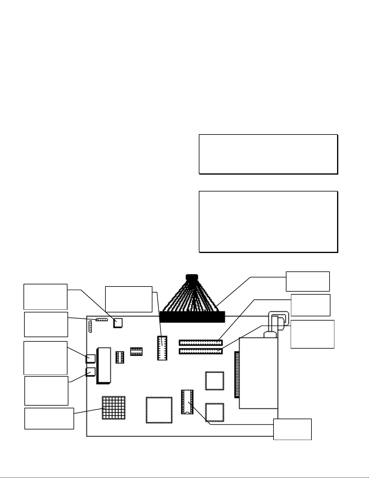
BIG BUCK HUNTER COTW
PCB CONNECTIONS JAMMA
Connector
Video
Card
Processor with
Heat Sink
Boot ROM
U15
Hard Drive
Connector
LED Sign
Connector
(Gray)
CD ROM
40-Pin
Connector
20-Pin ATX
Power
Connector
Phone Jack
for Outside
Line
Extra Phone
Jack used for
Daisy
Chaining
Rifle
Connector
BIG BUCK
HUNTER
MAIN PCB
Modem
Pin
32
Pin
16

Big Buck Hunter™ Page 6Version 01/05
© Copyright 2004-2005 Incredible Technologies, Inc. All Rights Reserved. Unauthorized duplication is a violation of applicable law.
All other marks are the properties of their respective owners. All rights reserved.
KIT GAME INSTALLATION
KIT PACKAGE CONTENTS
(1) Printed Circuit Board (PCB) Assembly
(1) Hard Drive and 40-Pin Ribbon Cable
(1) ATX Power Supply
(1) Gun Assembly
(2) Gun Mounting Clips
(1) Illuminated Button Assembly
(1) Card Reader Assembly
(1) Misc. Mounting Hardware
(1) Marquee Art
(1) Marquee Acrylic
(1) Control Panel Overlay
(1) Set Control Panel Labels
(2) Side Decals
(1) Set Installation Templates
(1) 50 ft. Telephone Cable
(1) Telephone Line Splitter
(1) Manual
RECOMMENDED TOOLS AND
SUPPLIES
•Phillips and Slotted Screwdrivers
•Socket Set, Wire Cutters and Strippers
•Pliers or Channel Locks
•Electric Drill with 3/32", ¼", and 7/16" Bits
•Chassis or Sheet Metal Punch
•Razor Knife and Sharp Blades
•Soldering Iron and 60/40 Resin Core Solder
•Assorted Fastening Hardware
•Heat Shrink Tubing (3/32", 1/8", and 3/16")
•Masking Tape or 4" Wire Ties
IF YOU DO YOUR OWN PAINTING, YOU'LL NEED
THESE PAINT SUPPLIES:
•Air Brush or Paint Sprayer
•Paint Brush, Paint Roller and Pan
•Paint (and Primer)
•Sandpaper
INSTALLATION
PREPARATION
BEFORE YOU START...
1. Check to see if all the needed parts have been
included in your kit or tournament cabinet.
2. Do you have the necessary tools?
3. Do not work with any part of the system plugged
in (lights, monitor, or power supply).
THE CABINET
Power Requirements
WARNING!
ATX Power Supplies require a load to operate. There
will be no Voltage Output if the power supply is not
connected to the main board.
Big Buck Hunter Call of the Wild requires an ATX
Power Supply, supplied with this kit. Make sure the
game you have chosen to convert is able to supply all
the required voltages for Big Buck Hunter Call of the
Wild.
+3 VDC 14 amps
+5 VDC 25 amps
+12 VDC 10 amps
WARNING!!!
The output level of many “regulated” switching power supplies
actually varies with load. For this reason, the power supply from
an old game may not be an ATX power supply required for a BIG
BUCK HUNTER™ RED BOARD. This makes the existing power
supply inappropriate and hazardous to your new game. Use only
a 250-Watt ATX Power Supply with the RED BOARD.
Monitor Requirements
BIG BUCK HUNTER requires a monitor in a
horizontal mount raster scan with negative composite
SYNC. It can be difficult to change the monitor from
vertical to a horizontal unit. Therefore, installation will
be easier if you choose a horizontal mount cabinet.
BIG BUCK HUNTER has been designed for medium-
resolution (mid-res) monitors. For best results,
choose a cabinet with a mid-res. monitor. Consult
your monitor for mid-res. adjustment.
ONLY Big Buck Hunter Call of the Wild Kits will work
with low-resolution monitors. Please check the dip
switch settings on Page 5 for correct settings.
CAUTION! Monitors are extremely dangerous and can result in
severe injury. Make sure you follow and observe all safety
precautions as outlined in your monitor’s manual.

Big Buck Hunter™ Page 7Version 01/05
© Copyright 2004-2005 Incredible Technologies, Inc. All Rights Reserved. Unauthorized duplication is a violation of applicable law.
All other marks are the properties of their respective owners. All rights reserved.
DRILL 1" HOLE
DRILL 3/16" HOLE
(2 PLACES)
START BUTTON
HOLE TEMPLATE
Cabinet Selection
You can choose either a new cabinet or a used
cabinet for your BIG BUCK HUNTER game. Reusing
a cabinet is by far the most cost-effective way to
maximize the return of your initial investment. In
either case, all you need to provide is a cabinet with a
power supply, bill acceptor and monitor. We provide
the rest. The end result is a new game at a very low
cost.
NOTE:
It is recommended that a cabinet used for similar types
of games be used for your BIG BUCK HUNTER. Large
monitors mounted at a right angle work best.
NOTE:
The monitor must be mounted perpendicular to the gun
for the game to play correctly.
When selecting a cabinet, keep this in
mind:
A cabinet with a 25" or larger monitor, mounted at a
right angle, will produce the best game play results.
The monitor must be perpendicular to the gun for the
game to play correctly.
1. Remove the following from the cabinet: Main
Logic Board(s), Control Panel, Monitor Plexiglas,
Marquee, Cabinet Graphics
2. Thoroughly clean out your cabinet. Remove all
the old buttons, joysticks and wires from the
control panel. DO NOT remove monitor and
speaker wires.
3. If your cabinet does not have switches or buttons
inside the cabinet, you will need to install them for
volume control and access to diagnostics and
testing modes.
4. Remove the old graphics and adhesive from the
control panel, and the side of the cabinet.
5. For a fresh look, painting is highly recommended.
Spray painting gives a better finish, but if an air
brush or paint sprayer is unavailable, a roller is
second best. Remember to cover all exposed
surfaces not to be painted.
6. The "new game look" should always apply to the
inside of your game as well. A few wire ties and
shrink tubing on your harness, some fastening
hardware on your subassemblies, and a sweep
with the vacuum cleaner will help ensure that
glitches do not occur.
CONTROL PANEL
Compare your cabinet’s control panel to the diagram
below to determine how to install the graphics and
controls. The BIG BUCK HUNTER gun holster is
mounted either on the front or side of the cabinet, so
your control panel requires very little drilling.
Button Preparation
Big Buck Hunter comes with an illuminated Start
button.
1. When making the hole for the Start button, use the
control panel layout diagram as a guide to where
you should drill your new hole, and mark the
center of the hole with a pencil.
2. Locate and Mark the center of the control panel.
3. Position and attach the Start Button Hole Pattern
Template to your control panel. Be sure that the
location you have selected is free from
obstructions inside the cabinet. Be sure that the
template is oriented correctly.
4. Carefully drill and deburr the 1” center hole, and
the two 3/16” mounting holes.
5. Use a file to smooth any rough edges on the
holes.
6. Fill any old and unused holes with wood, resin, or
a metal plate.
7. It is recommended that you cover your control
panel with Plexiglas. Now would be a good time
to cut it to fit while the dimensions and tools are at
hand.
Big Buck Hunter™ Page 8Version 01/05
© Copyright 2004-2005 Incredible Technologies, Inc. All Rights Reserved. Unauthorized duplication is a violation of applicable law.
All other marks are the properties of their respective owners. All rights reserved.
8. Install the control panel graphics and labels,
following the instructions found in the manual. Cut
away any graphics material from the button holes.
9. Insert the supplied button into the large hole. Two
pins on the lower edge of the button are used to
lock the button into position.
10. Tighten the large plastic nut securely onto the
plastic button housing.
11. Snap the micro-switch and lamp into the button
housing.
12. Attach the button assembly switch and lamp to the
main harness connectors. Refer to the manual for
correct wiring.
Volume and Test Switches
If your cabinet does not have switches or buttons inside
the cabinet, you will need to install them for volume
control and access to diagnostics and testing modes.
Big Buck Hunter requires three external switches to
navigate through Operator Mode. Install a Test, Volume
Up and Volume Down switch in a convenient location
inside your coin door. Volume Up and Volume Down
double as scroll up and scroll down when in Operator
Mode. Refer to the JAMMA Connections diagram for
proper wiring.
GRAPHIC OVERLAYS
BIG BUCK HUNTER comes equipped with graphics
that will accommodate a variety of existing game
cabinets. Remove any old control panel graphics and
make sure the panel is clean and free of dirt, grease
or adhesives before installing your new graphics.
Control Panel Overlay Installation
1. Make sure the control panel is clean and free
from dust, grease, metal filings, and sawdust.
The background overlay provided with the game
is oversized to accommodate most control panel
sizes. Center the background overlay on the
control panel surface. Be sure to leave enough
excess material above and below the control
panel in order to trim it evenly.
2. Remove the protective backing from the
background overlay. Center the background
overlay over the control panel and place down
gently, making sure to keep it square. Using your
hands, press down firmly, starting from the center
and smooth the background overlay outward,
making sure all bubbles have been pressed out
for a clean, flat surface.
3. Using a sharp razor knife, trim any excess from
the background overlay. Carefully pierce through
the overlay above the control panel hole that you
have marked. Cut out material covering the pre-
drilled holes with the razor knife. Be sure to cut
and trim the background overlay cleanly and
evenly.
Function Labels Overlay Installation
Line up the supplied function labels to correspond
with the control panel layout on the previous page.
Remove the backing and carefully press into place.
Be sure they are straight. Refer to the control panel
diagram for optimal placement. If you are protecting
your control panel with a Plexiglas overlay and have
already cut it install it now.
Insert the Start button into the control panel and
tighten securely. Refer to the Wiring section of this
manual for correct button wiring.
Marquee Installation
If your cabinet needs a new marquee Plexiglas,
determine the correct size and cut to fit. Using the old
marquee Plexiglas as a template, center the Plexiglas
on your new marquee, making sure that all the printed
images will be visible.
The supplied marquee is designed to fit in a
dedicated Big Buck Hunter as well as most universal
kit cabinets. When installing in a kit, you will need to
trim the marquee art to fit. Use the existing Plexiglas
from your cabinet to determine the proper trim size.
Refer to the diagram below for best results. Be sure
to leave enough room above and below the logos so
they are not cut off when installed.
Using a razor knife, carefully score the new marquee,
following the edges of the old glass. Carefully break
off excess material. Be sure the light behind the
marquee works and that the glass is clean on both
sides. Now install the marquee graphics and
Plexiglas securely.
Use the area below the LED section for kit marquee
Cabinet Side Graphics Installation
Remove any old side stickers. Be sure the surface is
smooth and clean. Carefully remove the backing
from the supplied logo stickers and smooth in place
on the side of your cabinet. Refer to the diagram
below for optimal placement.
Big Buck Hunter™ Page 9Version 01/05
© Copyright 2004-2005 Incredible Technologies, Inc. All Rights Reserved. Unauthorized duplication is a violation of applicable law.
All other marks are the properties of their respective owners. All rights reserved.
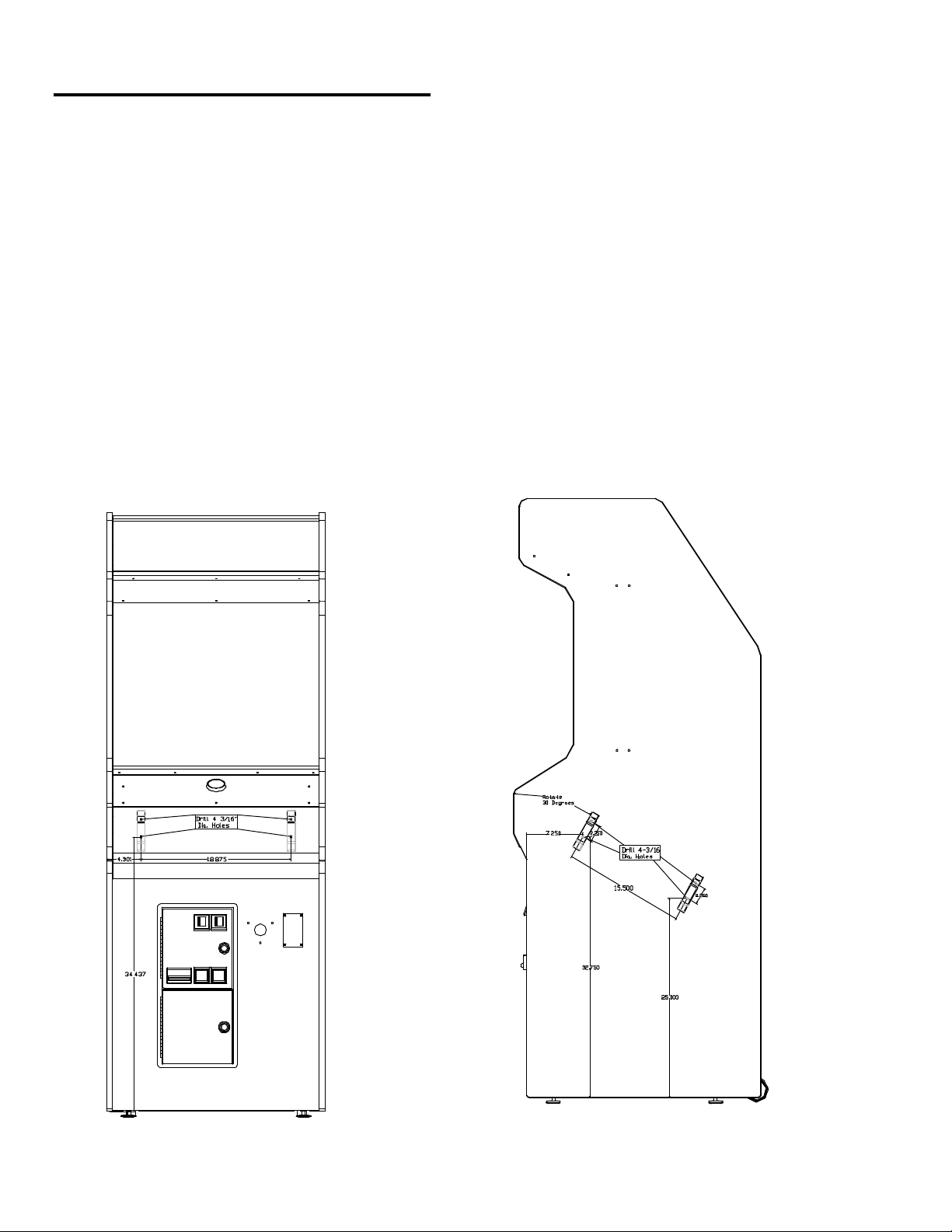
RIFLE HOLSTER INSTALLATION
Most BIG BUCK HUNTER games come equipped
with a specially designed rifle. To mount the rifle to
the cabinet, you need to attach a rifle holster. The
rifle holster consists of two high-impact plastic
brackets. These brackets can be mounted on the
front of your cabinet, or on the side of your cabinet.
1. Determine where you want to mount the holster.
The holster should be mounted at a comfortable
height near the control panel. Make sure the
cable attached to the rifle will reach the PCB
when mounted in the proposed bracket position.
2. Use the dimensions on the cabinet diagrams for
optimal placement.
3. For FRONT MOUNTING, center the template on
a vertical surface. Be sure the template is
oriented correctly. Match the center of the
template to the center line of the cabinet. Use
only the brackets on the template labeled A and
C. The center holes on the brackets should be
18.875” apart.
4. For SIDE MOUNTING, orient and attach the
template to the cabinet at a 30-degree angle. Be
sure the template is oriented correctly. Use only
the brackets on the template labeled A and B.
The center holes on the brackets should be 15.5”
apart.
5. Punch or mark the center holes for the
appropriate bracket mounting holes with an awl.
6. Remove the template and carefully drill and
deburr the four 3/16” mounting holes.
7. Install the brackets using the supplied carriage
bolts, flat washers and locking nuts. Fasten the
nuts securely inside the cabinet.
Big Buck Hunter™ Page 10 Version 01/05
© Copyright 2004-2005 Incredible Technologies, Inc. All Rights Reserved. Unauthorized duplication is a violation of applicable law.
All other marks are the properties of their respective owners. All rights reserved.
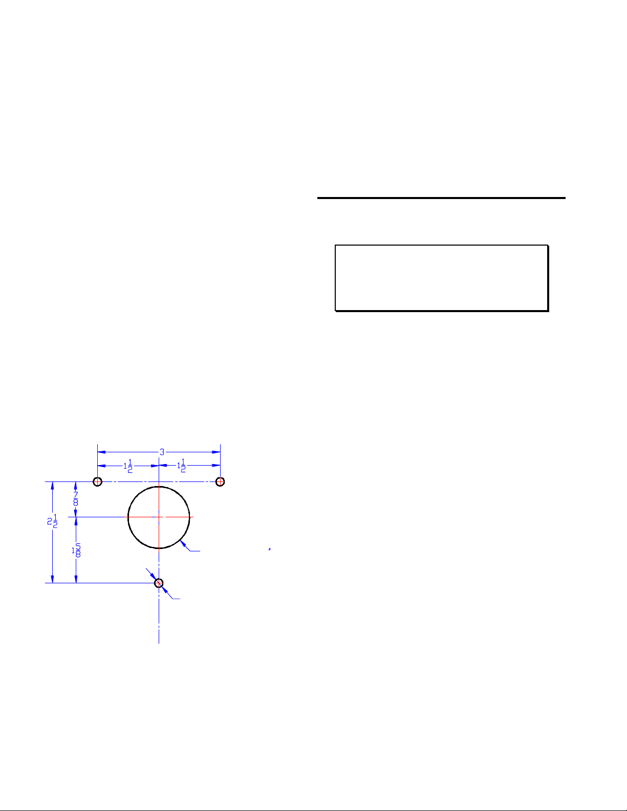
DRILL HOLE
7/32" (3 PLACES)
DRILL HOLE 1-1/2
GUN CABLE MOUNTING PLATE
HOLE PATTERN
Gun Installation
1. Insert the gun into the newly mounted holster.
The attached gun cable should be hanging freely,
with no loops or kinks.
2. Determine the best location for the gun cable
mounting bracket. Players should be able to
move the gun freely. Use the dimensions
indicated on the cabinet diagrams for
approximate placement. Be sure that once
installed, the wires from the gun cable assembly
will reach the power supply and PCB inside the
cabinet.
3. Position and attach the Gun Cable Mounting
Template to the cabinet. Be sure that the location
you have selected is free from bracing or wiring
inside the cabinet.
4. Carefully drill and deburr the 1 ½” center hole,
and the three .20 mounting holes.
5. Thread the cable connector and grounding wire
through the center hole.
6. Mount the Gun Cable Mounting Plate using the
supplied carriage bolts, flat washers and locking
nuts. Make sure the bolts are seated firmly.
Attach the grounding wire to any one of the
carriage bolts before installing the washer and
locking nut.
7. Once the Gun Cable Mounting Plate is mounted
securely, Make sure the gun can move freely in
all directions.
8. Inside the cabinet, connect the Cable Connector
to the supplied Connecting Harness. The
Connecting Harness then connects to GUN 1
connector on the main PCB. See the Wiring
section of this manual for more details.
WIRING AND HARDWARE
ASSEMBLY
REMEMBER! DO NOT WORK WITH ANY PART OF
THIS SYSTEM PLUGGED IN (Lights, Monitor, or
Power Supply).
NOTE:
All switch wires used in this game need to be wired to
the normally open connection on the switches. Each
switch requires a ground wire on the common
connector and the appropriate control or switch wire on
the other normally open connector of the switch.
Control Panel Assembly
Wire the controls using the JAMMA Harness
Connection table. Connect the gun using the supplied
connecting harness cable into GUN 1 on the main
PCB.
Printed Circuit Board (PCB)
BIG BUCK HUNTER uses a hard drive to store its
game data. Make sure you mount your PCB in such a
way as to allow easy connections to the hard drive
cables. Refer to the next section for suggested
mounting positions.
Big Buck Hunter™ Page 11 Version 01/05
© Copyright 2004-2005 Incredible Technologies, Inc. All Rights Reserved. Unauthorized duplication is a violation of applicable law.
All other marks are the properties of their respective owners. All rights reserved.
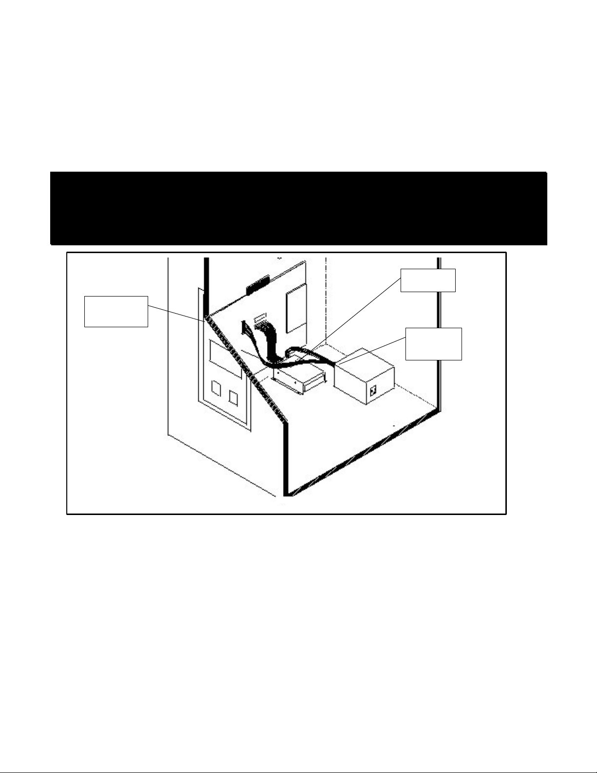
PCB and Hard Drive Installation
The hard drive is shipped with a mounting bracket already attached. The bracket allows installation with a minimal number
of steps and protects the electronics from damage due to improper handling. DO NOT REMOVE the bracket, as it may
cause damage to the hard drive. Use the diagram shown below for positioning the hard drive assembly in different types
of cabinets. Make sure to position the game board and the drive close enough for the two supplied cables to reach.
A data cable is supplied for the hard drive and is required for proper operation. Test fit the cable supplied for the hard
drive before securing to the mounting surface. See the insert for installation details. The supplied ribbon cable is for data
transmission. Connect one end of this cable to the keyed connector at J21 on the game board, and the other end into the
keyed connector on the hard drive. Also connect the 4-pin connector from the ATX power supply to the hard drive.
CAUTION!
Hard drives are sensitive to both physical and electrical shock. DO NOT DROP OR KNOCK OVER the hard drive.
Avoid shocks and other electrical discharges. DO NOT REMOVE the mounting bracket from the hard drive.
Removal may cause damage to the hard drive and will void the warranty. Keep the supplied padded box for
shipping any returns. Failure to use the supplied shipping box will void the warranty.
Installation in Lower Cabinet
1. Install the CPU Board on the inside wall of the cabinet (left or right), approximately 1 ½” above the cabinet floor.
Secure the CPU board using the ten supplied #6x3/4” hex washer head sheet metal screws.
2. Locate the Hard Drive on the cabinet floor, approximately 2” from the cabinet wall, and directly in line with the JAMMA
connector. Attach with 4 #8X ¾” wood screws (supplied). Avoid jarring or vibrating the hard drive with power
tools during installation.
3. Connect the keyed Hard Drive ribbon cable to J21 on the CPU board.
4. connect the 4-pin connector from the ATX power supply to the hard drive.
Returns
In kit games, the hard drive is shipped in a special padded box. In a dedicated cabinet, the shipping box is fastened to the
inside bottom of the cabinet. Be sure to keep this box, in case you need to ship the hard drive. Ship the bracket with the
hard drive. Do not remove the bracket from the hard drive. Failure to use the supplied box, or removal of the bracket, will
VOID THE WARRANTY on the hard drive.
RED BOARD
PCB
Hard Drive
ATX Power
Supply
J5
J22
J21
Big Buck Hunter™ Page 12 Version 01/05
© Copyright 2004-2005 Incredible Technologies, Inc. All Rights Reserved. Unauthorized duplication is a violation of applicable law.
All other marks are the properties of their respective owners. All rights reserved.
Wire Harness
1. If you are installing BIG BUCK
HUNTER CALL OF THE WILD
into a cabinet with a pre-installed
JAMMA harness, it may not have
a wire for the test switch. You will
have to add a contact to the edge
connector at the proper position
(position 15). Some cabinets
have only one coin switch input and the coin switches
are wired together. Connect the designated wires to
the coin switches separately.
2. Attach the wire harness connector to the PCB. Be
sure it is mounted correctly.
WARNING!
Make sure you have identified PIN 1 on the connector before
powering up. Plugging the JAMMA connector in backwards will
cause damage to the PCB.
3. It is best to use connectors (not supplied) whenever
joining a set of harness wires to a subassembly. If you
choose to solder wires together, follow this procedure:
4. Strip off about ½" of insulation from the wire.
5. Slide a piece of heat-shrink tubing over the end.
6. Do not leave a lot of excess wire spooled up in your
cabinet. Cut the wires to the length you need plus a
few extra inches. Leave enough for proper cable
dressing. Do not make it stretch across the inside of
the cabinet.
7. Solder the new wire to the original wire. Use a straight
in-line splice.
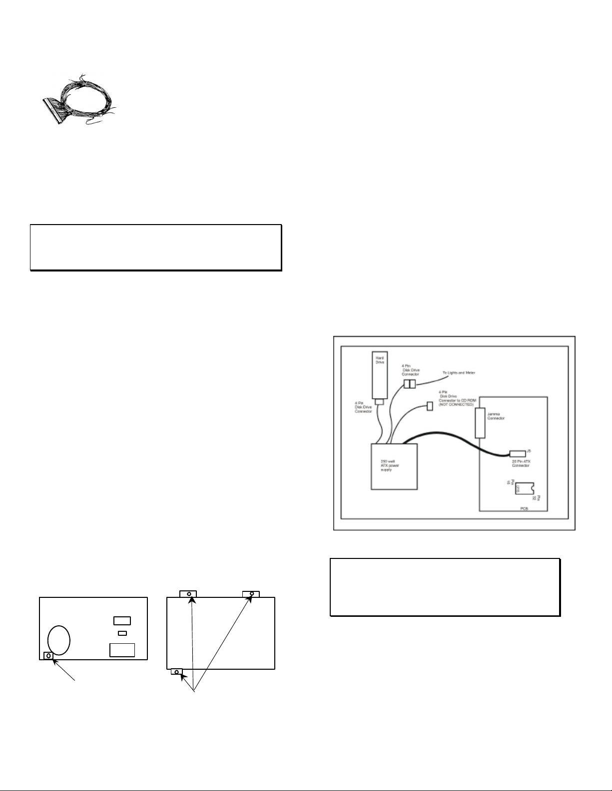
Power Supply and Connections
Because of current consumption, your Big Buck Hunter Call
of the Wild PCB connects directly to a 250-Watt ATX Power
Supply. To correctly mount the ATX Power Supply, you will
need to add a third bracket (supplied):
1. Attach the mounting bracket to the power supply using
the 6-32x1/4” machine screw.
2. Place the power supply in its intended location.
3. Secure the power supply using the three supplied #6x1/2”
hex washer head sheet metal screws.
Instructions for ATX Power Supplies:
1. Turn power to the cabinet and power supply completely
off.
2. Connect the 20-Pin ATX Connector directly into the RED
BOARD socket J5.
3. Locate one Hard Drive Power Connector from the ATX
Power Supply. Use this connector for powering lights,
meters and other non-PCB devices.
4. Locate another Hard Drive power connector on the ATX
Power Supply. Connect this to the Hard Drive.
5. The third Hard Drive connector from the power supply
remains unused. This is meant for future use to perform
updates with a CD ROM drive. Always be sure the CD
ROM drive is set to SLAVE Mode.
6. Turn power on while holding down the start button to
initiate a diagnostic test. Run this test to make sure your
RED BOARD is functioning properly.
7. Be sure to check your JAMMA connector and make sure
it is tightly connected. Detailed instructions and photos
of this installation can be viewed on the Operator
Services section of the IT web site, www.itsgames.com.
WARNING!
ATX Power Supplies require a load to operate. There will be
no Voltage Output if the power supply is not connected to the
main board.
Back View
New Bracket Top View
3 Mounting Brackets
Big Buck Hunter™ Page 13 Version 01/05
© Copyright 2004-2005 Incredible Technologies, Inc. All Rights Reserved. Unauthorized duplication is a violation of applicable law.
All other marks are the properties of their respective owners. All rights reserved.
SYNC
This is the recommended approach for a Wells-Gardner
monitor and should work with some others as well.
If your monitor does not have a composite SYNC input but
has separate horizontal and vertical SYNC inputs, try
connecting the composite SYNC signal from the PCB to
the negative horizontal SYNC signal on the monitor. This
should produce a satisfactory result, although some
adjustment of the monitor's SYNC controls may be
necessary.
Coin Doors, Test Switch, and Volume
Control Panel
Wire the coin doors and the test switch(es) as per the
JAMMA Harness Connection table on page 35. Connect
the door lamps to the +12 vdc supply. Some games have
separate power supply outputs for the lamps.
Install a test switch somewhere convenient inside the coin
door area. This switch allows you to enter adjustables, run
diagnostics, and see or clear audits. Make it readily
accessible through the coin door. Wire it to the Test wire
on the JAMMA Harness.
BIG BUCK HUNTER has the ability to adjust volume at
any time during a game. Install two push button switches
(not included) inside the coin door for easy access.
Connect the switches to the JAMMA harness. Refer to the
JAMMA Harness Connection table on 35.
Final Check
Check the game inside and out for any imperfections.
Secure any loose wiring or fastening hardware.
Make sure the coin door is tight and the coin mechs are
well adjusted.
NOTE:
Make sure all assemblies are firmly attached. Anything that is
not mounted securely will rattle when the game is played.
This game makes use of low-frequency sounds that can
cause any loose joints to rattle.
DIP SWITCH SETTINGS
The SW51-Dip switches can be found on the main PCB
near the JAMMA connector.
Dip Switch 1 (ON): Normal Play (DEFAULT)
Dip switch 1 (OFF): OPERATOR MODE
Dip switch 2 (ON): Always "ON" (DEFAULT)
Dip switch 3 (ON): Always "ON" (DEFAULT)
Dip switch 4 (ON): Always "ON" (DEFAULT)
The SW5-Dip switches can be found near the flashing
green LED. These are used to adjust monitor resolution in
Kits.
Dip switch 1 (OFF): Medium Resolution (DEFAULT)
Dip switch 1 (ON): Low Resolution
**Dip switch 2 (OFF): Low Resolution B Adjust
Dip switch 2 (ON): Low Resolution A (DEFAULT)
Dip switch 3 (ON): Always "ON" (DEFAULT)
Dip switch 4 (ON): Always "ON" (DEFAULT)
**If you are experiencing a “jittery” image, try this mode to
correct. Restart the game and adjust the monitor
Note: Low-resolution works on BBH KITS ONLY!
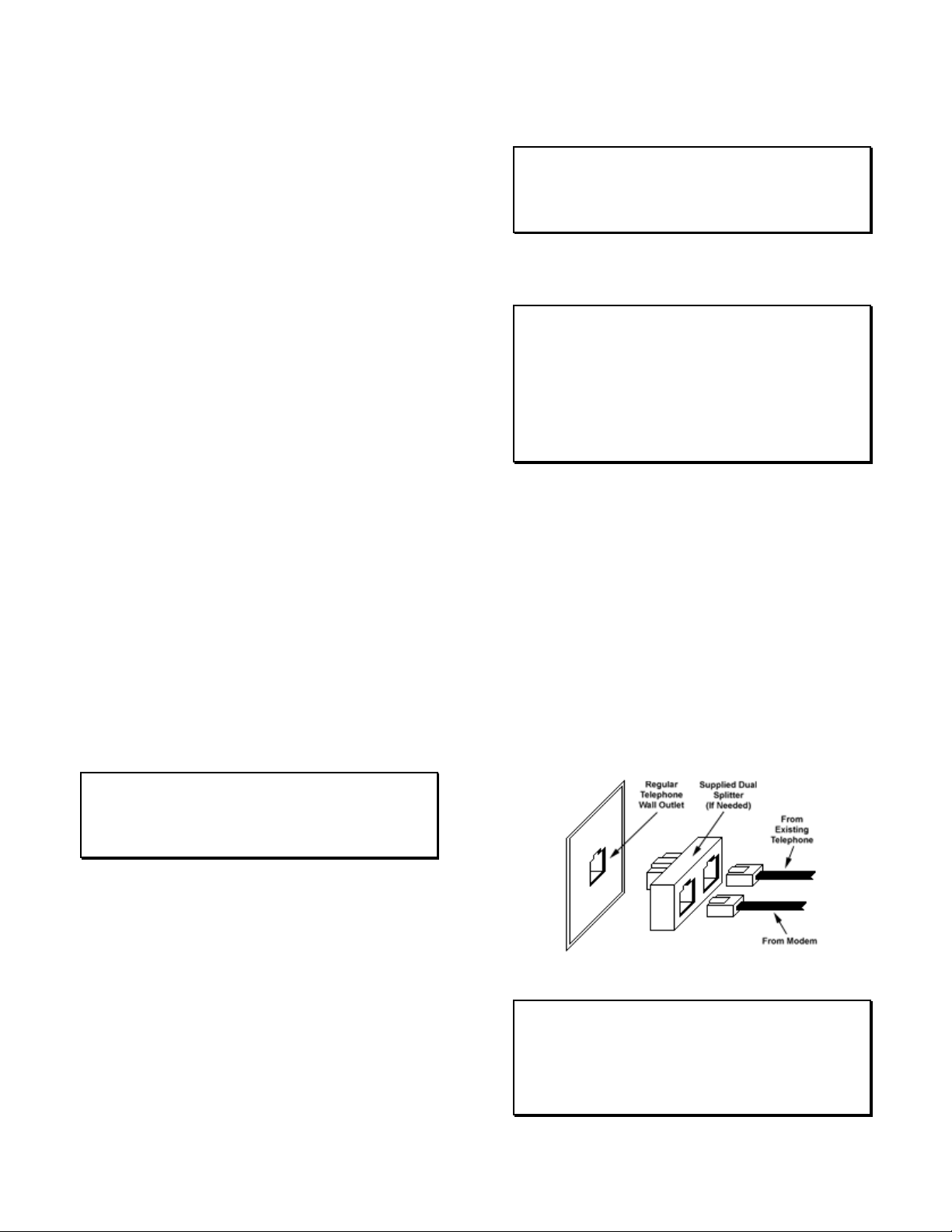
CONNECTING THE PHONE
LINE
In order for your game to enjoy online features, you must
connect the game to a regular telephone line. ITNet
requires a regular phone line that gives a dial tone. Phone
systems that are not direct outside lines may not work.
1. Make sure that the supplied long telephone cable is
plugged into the modem connector on the PCB labeled
PHONE 1. Thread the cable through the mouse hole
below the back door.
2. Connect the loose end of the long cable into any
existing telephone jack. Use the included splitter if you
are connecting to a jack already in use.
Connecting to the Wall
IMPORTANT!
Your game will receive code updates through the phone line,
even if you are not registered with the ITNet system.
However, you MUST be registered with ITNet and
appropriate operator papers must be on file wi th Incredible
Technologies, Inc. or your game will not receive the ITNet
play features.

Big Buck Hunter™ Page 14 Version 01/05
© Copyright 2004-2005 Incredible Technologies, Inc. All Rights Reserved. Unauthorized duplication is a violation of applicable law.
All other marks are the properties of their respective owners. All rights reserved.
NODE CONNECTIONS
If you are planning to place more than one online machine
in a location, you may want to connect them together so all
of the ITNet machines share the same phone line. Follow
the directions below to correctly daisy chain your cabinets
together.
ITNet games can be connected together and share one
phone line. Connect the first game cabinet to the phone
line following the directions on the previous page.
From the first cabinet, connect the long round 50-foot
telephone cable that is supplied with each game, to the
phone jack on the PCB marked PHONE2. Connect the
other end of this cable into the phone jack marked
PHONE1 on the next cabinet in line. If a third cabinet is to
be connected, attach another telephone cable to the jack
marked PHONE2 on the second cabinet. Attach the other
end of the cable to the jack marked PHONE1 on the third
cabinet. Repeat this sequence until all of your tournament
machines are daisy-chained together.
INITIAL POWER-UP
1. Connect the JAMMA Harness.
WARNING!
Make sure the JAMMA harness, hard drive, and all other
connections are plugged in correctly. Damage to the PCB will
occur if the JAMMA connector is plugged in wrong.
2. Check the game inside and out for any imperfections.
Secure any loose wiring or fastening hardware.
NOTE:
Make sure all assemblies are firmly attached. Anything that is
not mounted securely will rattle when the game is played.
This game makes use of low-frequency sounds that can
cause any loose joints to rattle.
3. Plug in the game and turn it ON.
4. Look and smell for smoke (TURN IT OFF
IMMEDIATELY IF ANY IS NOTICED).
5. Make sure the LED’s on the PCB are flashing. If not,
something is wrong, turn off the game.
6. Listen for sound. Sounds should be heard in the attract
mode if it is a new game on for the first time.
7. How is the picture? Is it centered? Is it too bright? Is it
in focus? Adjust your monitor to get the best picture
possible.
NOTE:
Check your monitor manual to make adjustments. Some test
patterns are available through the game's system tests by
pressing the Test switch. Use them when making any
adjustments. (See System Tests Menu on page 28). Proper
monitor adjustment is very important.
8. Try all coin switches. Drop quarters or tokens through
to check the coin mechs. Insert a dollar bill into the bill
validator and listen for the credits to ring up. Make
sure the game is adding credits. You can use the
PLAYER CONTROL TEST by pressing the test switch
and entering the SYSTEM TESTS MENU. Do all of the
controls work? Try playing the game with the volume
up and listen for rattling as you play. Tighten anything
that is making noise.
9. Upon initial power-up, the game will initialize to factory
default settings. These settings affect game elements
such as number of credits per coin, difficulty settings,
etc. The OPERATOR ADJUSTABLES MODE section
will describe how to alter these settings and view the
system audits or run system tests.
10. If you wish to automatically run a series of system
tests, hold down the START button when you power
up the game cabinet. The game will automatically
perform the MAIN MEMORY, VIDEO MEMORY,
PLAYER CONTROL, SOUND TEST, and HARD
DRIVE tests. This is a good, quick way to check the
integrity of your PCB.

Big Buck Hunter™ Page 15 Version 01/05
© Copyright 2004-2005 Incredible Technologies, Inc. All Rights Reserved. Unauthorized duplication is a violation of applicable law.
All other marks are the properties of their respective owners. All rights reserved.
ITNET OPERATOR
REGISTRATION
Follow these simple instructions to become eligible to
operate ITNet online features. If you are already a
registered ITNet operator, you can skip steps 1
through 4.
1. Fill out the ITNet Debit Account Form, found in
Appendix B, and open a Debit Account at your
local bank.
2. Read and sign the ITNet Operator Agreement,
found in Appendix B.
3. Fax or mail these two forms to Incredible
Technologies, Inc. to become an authorized ITNet
Operator.
4. Once these forms are processed, you will receive
your ITNet Operator ID Card in the mail.
The Operator ID Card allows you to:
Register your games for online play right on-site.
Activate games, add and change location
information, and de-activate games at the location.
Gain access to the personalized IT Operator
Services web site.
Check audits and bookkeeping from your home or
office.
NOTE:
If you are a brand new ITNet operator and can’t wait for your
Operator ID card to arrive in the mail, you can fax the GAME
REGISTRATION FORM, found in Appendix B, to Incredible
Technologies. The ITNet staff will then enter your machine’s
location data for you. Please allow 2 to 5 business days for
processing. When your machine calls in, it will automatically register
to your account and activate the online features.
ITNET INSTALLATION
PROCEDURE
Follow these simple instructions for game and ITNet
setup.
1. Follow the instructions to the left to become an
ITNet operator and receive your Operator ID card.
2. Set up your ITS-compatible game cabinet as you
would any other video game. If you have a
tournament version, be sure the LED sign is
properly connected or you will not receive
tournament play. Refer to other sections in this
manual for further help. Power should remain
OFF at this point.
3. Turn on the game. You may have to wait a few
seconds for hard drive access. If the game is not
registered a screen will appear asking you to
swipe your operator card to start the registration
process. If you do not have your card, or do not
have it ready, it will time out after 60 seconds.
4. If the game is already turned on you can still use
your card to register your game. Enter Operator
Mode by pressing the test button inside the coin
door. Then from the MAIN MENU, select ITNet
MENU, then GAME AND LOCATION
REGISTRATION. Follow the On-screen
instructions. Insert your ITNet Operator
Identification Card when prompted.
NOTE:
If you do not have your Operator ID Card yet please fax in a
Game Registration Form. The ITNet staff will then enter your
machine’s location data for you. After the form has been
processed and your machine calls in, it will automatically
register to your account and activate the online features.
5. Enter all of the necessary location information
carefully and accurately. When completed, the
game will automatically attempt to connect to
ITNet. Pay attention to the various screen
messages as the game makes its call, to spot any
trouble areas.
6. Automatic installation is successful when the
screen displays a SUCCESSFUL message. If any
unsuccessful message appears, the game will try
again automatically in a few minutes, or you can
enter Operator Mode by pressing the test button
inside the coin door and manually force a call. If
your first few attempts to call are unsuccessful,
refer to the troubleshooting guide in your manual
or call your distributor.
7. The game is now connected to the ITNet System
and ready for public play! Online features will be
automatically activated by Incredible Technologies
via ITNet.
Big Buck Hunter™ Page 16 Version 01/05
© Copyright 2004-2005 Incredible Technologies, Inc. All Rights Reserved. Unauthorized duplication is a violation of applicable law.
All other marks are the properties of their respective owners. All rights reserved.
OPERATOR TEST MODE
If your game is registered to ITNet, you can use your
Operator ID Card to enter Test Mode. Or, you can
enter the Operator Test Mode by pressing the Test
Button inside the coin door, or by flipping SW51-DIP
Switch 1 to the OFF position. Be sure the DIP Switch
is returned to the ON position to return to the game.
Test Mode allows you to adjust certain game settings
and track valuable audits and bookkeeping
information.
Use the gun or test buttons to navigate through the
various menus.
Action Gun Control Switch Control
Scroll Down Gun Trigger Volume Down
Scroll Up Gun Pump Volume Up
Select Start Button Test
Note:
The current code version number and the Board Serial ID are
displayed at the top of every menu. Call-in information is
displayed at the bottom of each menu, including the Local time,
the next scheduled call to ITNet, the last successful ITNet call,
and the last attempted call to ITNet.
MAIN MENU
The first screen displayed in Operator Test Mode is
the Main Menu. The Main Menu displays the various
selections available to the operator.
ITNET COLLECTIONS & AUDITS RESET displays
the current machine coin counts, for use in separation
of ITNet fees from your collections. You can also
perform collections and audits resets from this menu.
OPERATOR ADJUSTABLES MENU is used for
customizing the game to your location including player
costs per game, skill level settings, attract mode
sounds, etc.
GAME AUDITS MENU allows you to check your
game’s coin, purchase, region and lifetime coin audits.
ITNET MENU is designed to take advantage of many
of the ITNet capabilities including registering your
machine with ITNet, disabling/enabling calls to ITNet,
and forcing a call to ITNet.
SYSTEM TESTS MENU verifies the operation of the
hardware, controls, and monitor through easy and
automatic procedures accessed through this menu.
GUN CALIBRATION MENU calibrates the gun for
aiming and accuracy, to achieve optimal game play.
MAILBOX is currently not functional in Big Buck
Hunter Call of the Wild.
HIGH SCOREBOARDS MENU gives you quick and
easy access to the Regular Play (offline) leaderboards
for each region.
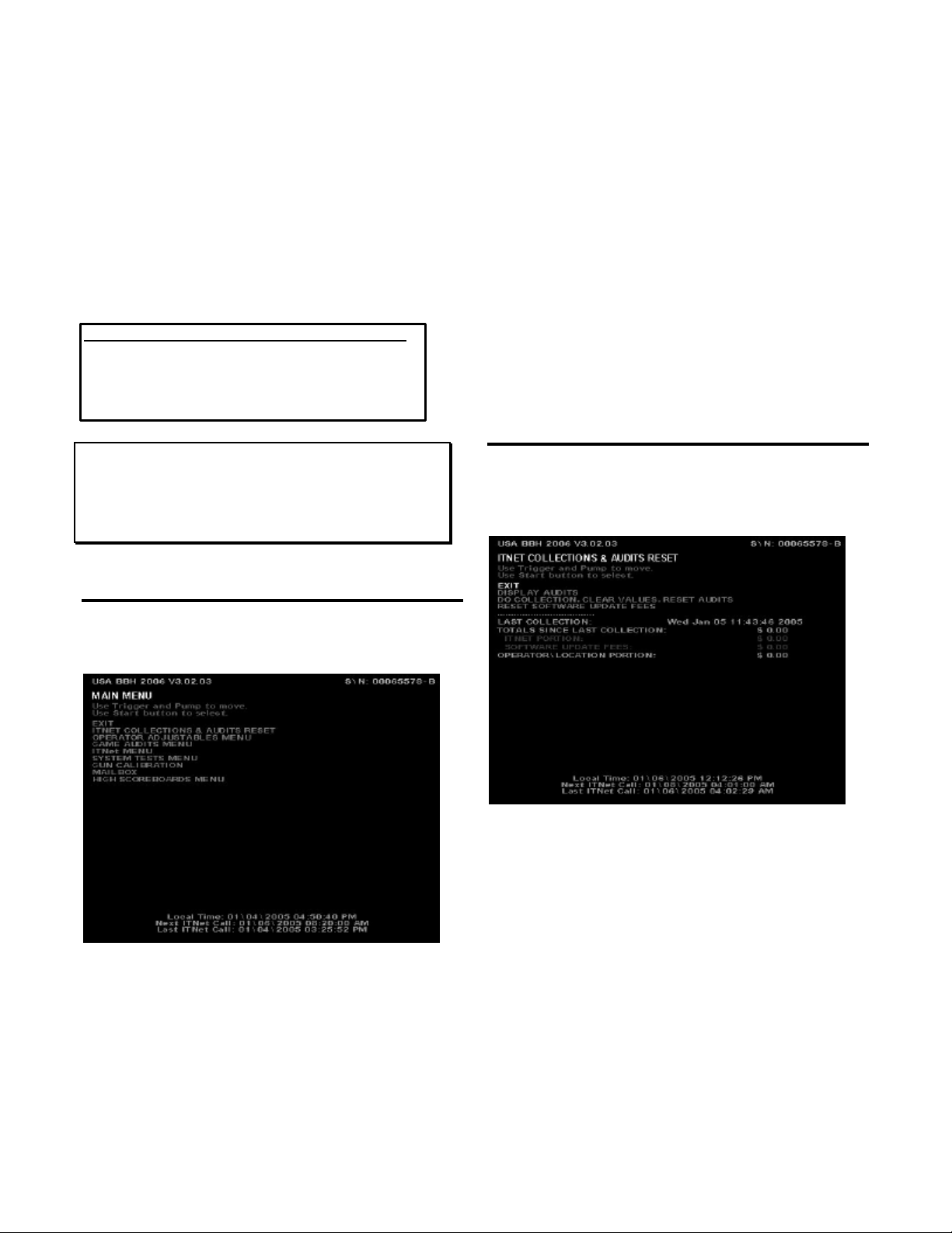
ITNET COLLECTIONS &
AUDITS RESET
Use this screen to assist in bookkeeping when doing
collections from your cabinet. This will show you the
amount of money owed to ITNet as well as your
portion currently in the cabinet.
EXIT is used when you just want to see the current
amount of money in the machine but a collection is not
being made and you do not want to clear the values.
DISPLAY AUDITS will take you to the game audits
menu. This can be useful when trying to do
bookkeeping right at the cabinet or for seeing why the
ITNet portion is a certain amount.
DO COLLECTION, CLEAR VALUES, RESET
AUDITS is used to erase all of the collection counts
stored in memory and reset the game audits. Pressing
the START button here will take you to a verification
screen asking if you are sure. If you say NO, it will take
you back to the collections screen leaving all counts
intact. If you say YES, it will complete the collection
and take you back to the collections screen. You will
notice all dollar amounts are now zero and two
messages stating the collections were cleared and the
audits reset will show up at the bottom in red.
Big Buck Hunter™ Page 17 Version 01/05
© Copyright 2004-2005 Incredible Technologies, Inc. All Rights Reserved. Unauthorized duplication is a violation of applicable law.
All other marks are the properties of their respective owners. All rights reserved.
RESET SOFTWARE UPDATE FEES lets you set your
current software update fee to zero. The Software
Update Fee displays any money owed if an update is
purchased through an ITNet payment plan. These
fees are billed through ITNet and are not part of your
cash box collection. However, your fee is included on
this screen as a courtesy to you, if you wish to have
your location help you pay a portion of your update
charges. The Software Update Fee is calculated over
12 months on a per-day basis, starting from the time of
purchase.
This screen also displays important collection
information that allows you to accurately determine
your split with your location. Resetting this screen
after every cash box collection will ensure the most
accurate results.
LAST COLLECTION displays the date this screen
was cleared last. Clearing this screen in conjunction
with every collection will keep your readings the same
as your cash box.
TOTALS SINCE LAST COLLECTION displays the
total number of dollars in the machine since the audits
were last reset.
ITNET PORTION displays the amount of money owed
to ITNet. Separate this amount from your collection
before you make your split with the location. Deposit
this amount into your debit account on a timely basis
to ensure proper funds.
SOFTWARE UPDATE FEE displays any money owed
if an update is purchased through an ITNet payment
plan. These fees are billed through ITNet and are not
part of your cash box collection. However, your fee is
included on this screen as a courtesy to you, if you
wish to have your location help you pay a portion of
your update charges. The Software Update Fee is
calculated over 12 months on a per-day basis, starting
from the time of purchase.
OPERATOR/LOCATION PORTION displays the
amount of money in the machine, minus the ITNet
portion. This is the amount of your collection that you
may split with your location.
NOTE:
In order to make bookkeeping easier, all audits but the lifetime
coin count will reset with each collection, making everything
more synchronized.
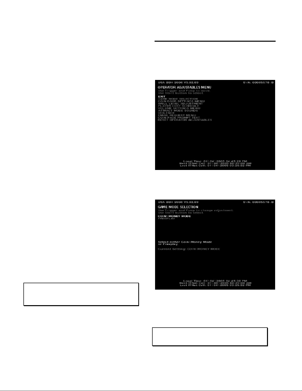
OPERATOR ADJUSTABLES
MENU
You can control many customizing procedures. The
following are brief descriptions of each adjustable
function and what the screen looks like when
displayed. Remember to select an item from any
menu, use the trigger or pump to highlight the item,
and then press the START button.
GAME MODE SELECTION
This menu allows you to place the game in standard
COIN/MONEY MODE, or choose FREE PLAY.
In COIN/MONEY MODE, the game will only work if
coins (or dollar bills if you have a bill acceptor) are
deposited into the game.
In FREE PLAY, coins are not needed for play, and the
START button is always active.
NOTE:
If FREE PLAY is set to ON, your machine will not allow
tournament or Hunt Club play.

Big Buck Hunter™ Page 18 Version 01/05
© Copyright 2004-2005 Incredible Technologies, Inc. All Rights Reserved. Unauthorized duplication is a violation of applicable law.
All other marks are the properties of their respective owners. All rights reserved.
COIN DOOR SETTINGS
This menu allows you to change the values that Big
Buck Hunter reads in for each activated door.
You can set each coin door to different coin/money
values by highlighting DOOR 1 VALUE for coin door 1,
DOOR 2 VALUE for coin door 2, etc., and pressing the
Start button. Use the trigger to decrease the value,
and the pump to increase the value.
SKILL LEVEL ADJUSTMENT
Big Buck Hunter Call of the Wild lets you change the
skill level of the game. This is helpful for locations with
younger/novice players who are less skilled at the
game, or expert/accomplished players who demand a
greater challenge.
To set the game to an easy skill level, highlight EASY.
To set the game to a difficult skill level, highlight
HARD. MEDIUM is the default skill level and
approximately the skill required for the average player.
Sometimes it is best if the skill level is adjusted
gradually over a period of time.
NOTE:
The skill level adjustment will only affect regular play. The
skill level on all Tournament games is controlled by ITS via
ITNet, so every machine plays the same. Hunt Club Play is at
a pre-set, unchangeable level.
PLAYER COST SCHEDULE
The following costs can be set in this menu:
TRIP and REGION (offline play selections), TRIP
HUNT CLUB and REGION HUNT CLUB (online play
selection), BONUS ONLY HCLUB (4 Bonus rounds),
and TOURNAMENT for tournament play.
To change any of the costs press the trigger to move
to the option you want to change. Then press the Start
button to select.
NOTE:
This function will only change the OPER FEE, determining the
amount you receive for each game option. Changing the
OPER FEE automatically changes the TOTAL column. The
ITNET FEE is a pre-set, unchangeable amount that will be set
and adjusted by ITNet automatically if needed. Player
Hunting Licenses have pre-set OPER FEEs and ITNET FEEs
set by ITNet.
VOLUME SETTINGS
Select MINIMUM VOLUME with the Start button to set
the softest the sounds will go.
Once selected text appears to the right. Use the trigger
and pump on the gun to set the lowest sound value.
The default setting is 30.

Big Buck Hunter™ Page 19 Version 01/05
© Copyright 2004-2005 Incredible Technologies, Inc. All Rights Reserved. Unauthorized duplication is a violation of applicable law.
All other marks are the properties of their respective owners. All rights reserved.
GAME VOLUME sets the volume of the sounds and
music during the game. The default setting is 200.
ATTRACT MODE VOLUME sets the loudness or
softness of the sounds and music when no one is
playing. The default setting is 120.
Your cabinet is also equipped with volume
increase/decrease push buttons located inside the
coin door. These buttons will adjust the current mode
that the game is in. For example, if you are in the
attract mode, the volume buttons will only affect the
volume in the attract mode. If you are in the game, the
volume buttons will only affect the volume in the game.
ATTRACT MODE SOUNDS
This menu is used to adjust the sounds that are heard
while no one is playing the game.
ATTRACT MODE SOUNDS -OFF will not allow any
sounds to be played during the attract mode.
ATTRACT MODE SOUNDS -ON OCCASIONALLY
plays sounds about every ten to twelve times the
attract mode is repeated. This is the default.
ATTRACT MODE SOUNDS -ON ALWAYS will play
sounds during every attract cycle.
VIOLENCE
Big Buck Hunter Call of the Wild allows you to adjust
the violence settings on the game, depending on the
location.
NORMAL violence settings display some blood as the
bucks are shot. This is the default setting.
NO BLOOD removes the graphic elements such as
blood, but the audio references to shots and gunfire
remain.
TAGGING ONLY removes all video and audio
references to killing or blood, and replaces them with
references to humane tagging.
EMAIL REQUEST MENU
Your Big Buck Hunter Call of the Wild game will ask
players if they wish to join the ITNet Email Club, where
they will receive periodic information on ITS
tournaments, special events and other exciting news
designed to keep them interested and playing your
games. You can turn this feature off by selecting OFF
from this menu.
Table of contents
Popular Game manuals by other brands

New sports
New sports E-Dartboard instruction manual

Millennium 2000
Millennium 2000 Luxe Cabinet manual

Innovative Concepts in Entertainment
Innovative Concepts in Entertainment SUPER TRIVIA Owner's and service manual

Learning Resources
Learning Resources Sequencing Puzzle Cards LER 1577 manual

PAOKAI ELECTONIC ENTERPRISE
PAOKAI ELECTONIC ENTERPRISE WMH-288B1 TV user manual

Hasbro
Hasbro AGES 4+ instruction manual


