INDCO HS-5 Series User manual
INDCO, Inc. M-M-30118 mixer manual HS-5 date: 3/8/05
HS-5 SERIES
DISPERSER
Contents Page
Safety, General & Installation ... 3
Operation ...... 4
Maintenance ...... 5
Electric Motor Data & Troubleshooting . . 6
Parts List ......10
HS-5
Series
Disperser
OWNERS
MANUAL
INDCO, Inc.
4040 Earnings Way
New Albany, IN 47150
phone: 812-941-5954
fax: 812-944-9742
web: www.indco.com
Warranty
Our products are guaranteed against
defective materials and workmanship, we will
repair or replace such items as may prove
defective at our option. Warranty period is
one year on items manufactured by INDCO.
On items not manufactured by INDCO, the
manufactures warranty applies. All
component parts of our products are covered
by this warranty, except for normal wear items
such as belts or impellers. We cannot be
responsible for damage or abuse to equipment
caused by improper installation or operation.
Warranties can also be voided by
unauthorized disassembly of equipment. For
warranty repairs, equipment is returned to
INDCO at the customer’s expense; we will
repair and return to customer at our expense.
Under no circumstances will we allow labor
charges or other expense to repair defective
merchandise. This warranty is exclusive and
is in lieu of all other warranties, whether
express or implied. INDCO shall not be liable
for any other damages, whether
consequential, indirect, or incidental, arising
from the sale or use of its products.
page 1 of 11

INDCO, Inc. M-M-30118 mixer manual HS-5 date: 3/8/05 page 2 of 11
Dispersers - Variable Speed Electric
Model:
Serial No.:
Date:
Order No.:

INDCO, Inc. M-M-30118 mixer manual HS-5 date: 3/8/05
General
The HS-5 series 5-horsepower electric powered high-speed
dispersers are designed for small production batches.
Each model comes complete with following features:
• Variable speed:
- Mechanical belt drive: 600 to 4000 RPM.
- Electronic inverter drive: 180 to 3600 RPM.
• Impeller shaft: 1.25” dia. - 316 stainless steel.
• 6” design ‘A’ disperser blade - 304 stainless steel.
• Pneumatic cylinder lift mechanism, 36” travel range.
• Container holder with capacity for 55-gallon drum.
• TEFC or Explosion-Proof electric motor.
• Optional tachometer.
Installation
Receiving:
Before removing any packing, visually inspect the exterior
of the shipment for any sign of damage. Should there be
any damage, bring it to the attention of the delivering UPS
or truck line and note the same on the receiving ticket.
Should there be damage you must place a claim with the
truck line. They are the only ones who will pay for the
damage done and you are the only one who can place that
claim.
Mounting:
Ensure the unit is securely bolted to your floor and is level,
square, and plumb. Leave space around the unit for
cleaning, inspection and maintenance.
Pre-Start Up Check List:
1. Are all mounting bolts tight?
2. Is disperser blade mounting bolt tight?
3. Has electric motor been wired according to the diagram
on the motor label? Is motor grounded?
4. Does motor have emergency stop located as per local
code?
5. Bump motor and check rotation, looking down into the
container, shaft should rotate clock-wise. If direction is
incorrect reverse motor as explained on the motor label.
Safety
Please follow the below safety precautions. Read this
complete manual before trying to operate your mixer.
Failure to follow these instructions could result in serious
bodily injury or death.
• Never move the unit without a suitable lifting device.
• Have a qualified individual bring power to your unit.
• Always ground the unit.
• Never run the unit in open air.
• Never adjust the speed without the unit running.
• Always lockout the power when working on the unit.
• Always use the container holder to restrain the container
during operation.
Electric Motor Safety:
Motors should be installed, protected and fused in
accordance with latest issue of National Electrical Code,
NEMA Standard Publication No. MG 2 and local codes.
Eyebolts or lifting lugs are intended for lifting the motor
only. These lifting provisions should never be used when
lifting or handling the motor with other equipment (i.e.
gearboxes or other driven equipment) as a single unit. Be
sure eyebolt is fully threaded and tight in its mounting hole.
Eyebolt lifting capacity rating is based on a lifting alignment
coincident with the eyebolt center-line.
Eyebolt capacity decreases as deviation from this alignment
increases. See NEMA MG 2.
Frames and accessories of motors should be grounded in
accordance with National Electrical Code (NEC) Article 430.
For general information on grounding refer to NEC Article
250.
Rotating parts such as pulleys, couplings, external fans,
unusual shaft extensions should be permanently guarded.
Keep hands and clothing away from moving parts. Trained,
qualified personnel should make electrical repairs only.
Mechanical Variable Speed Drive Safety:
When maintenance is required in the area of the equipment
necessitating removal of the guarding, the prime mover
should be turned off and “locked out”.
The user of variable speed belt drives should be aware of
the hazards through misuse of the product or failure to
protect against contact with moving parts.
Spring-loaded pulleys should never be disassembled without
first receiving instruction from factory.
Rapid acceleration or braking, or shock loading may cause
a shaft to fracture due to torsional twist beyond its capacity.
All mounting screws on the pulleys must be kept tight.
Even though each pulley is individually balanced at the
factory the system in which the pulleys operate may
resonate, particularly at high RPM’s over 1800. Sometimes
a new belt will reduce vibration levels in a system.
page 3 of 11
INDCO, Inc. M-M-30118 mixer manual HS-5 date: 3/8/05
CAUTION:
• Never run mixer without an impeller.
• Never run the impeller in open air.
• Never run impeller outside a container.
Dispersion “rules of thumb” include:
10-HP is required for every 100-gallons, under 20,000-cPs.
Single shaft dispersers are not recommended for product
over 50,000-cPs. The liquid level should equal the liquid
diameter. In general the disperser is run at blade tip speeds
of 4,000 to 6,000 Feet-Per-Minute. FPM = rpm x 0.262 x
blade diameter, in inches. The lower ranges are used for
agitation or blending operations while the upper ranges are
used for dispersions of difficult materials. The middle range
is adaptable to a great many solutions and easier
dispersions. Experience by the operator will be the best
key as to what speed to try first on materials handled at
your facility.
The blade should equal 1/3rd the tank diameter and be
center, vertical mounted. Under normal operation the blade
is located from 1 to 1.5 blade diameters from the bottom.
If this results in an excessive vortex, the blade may be
lowered. If the action is a little slow at the above location,
the blade may be raised to a limit of 2.5 diameters to obtain
a good flow providing the amount of material over the blade
is greater than the amount of material beneath. At this
point, good action is usually assured in the bottom of the
container.
When adding materials to the container for a test, always
introduce the liquid phase first. In most cases, the disperser
should be started and solid phase added. However, on
some formulations such as enamel, particularly those of
colored pigments, it has been found most satisfactory to
add vehicle in tank and then add all pigments before turning
on motor.
Air Cylinder Operation:
Before connecting your air supply ensure the lift control
valve is in the center (off) position. The valve lever is spring
loaded to rest in the center position. Connect your air supply
to the quick connector on the 3-position control valve.
Maximum air pressure is 100 PSI. Note that air pressure is
used to both raise and lower the cylinder. The following will
enable you to adjust the height of the impeller or to install
and remove your batch container:
CAUTION: After the air line is installed and before operating
the machine for the first time, move the lift control valve to
the downward position. This will charge the air cylinder
and prevent surging when the lift control valve is moved to
the upward position.
• Lifting:
Move the lift control valve to the up most position. To
stop upward motion move valve to center (off) position.
• Hold:
To hold the impeller at any height move the lift control
valve to the center (off) position.
• Lowering:
Move the lift control valve to the down most position.
To stop downward motion move valve to center (off)
position.
Electronic Speed Control:
Baldor SmartMotor® Inverter-Duty models have an
electronic keypad variable speed control. Speed range is
180 to 3600 RPM.
Mechanical Speed Control:
Units with the mechanical variable speed belt drive have a
speed range of 600 to 4000 RPM.
Turning the hand-wheel at the rear of the disperser varies
the speed. For best results always stop and start the
disperser in the lowest variable speed hand-wheel setting.
NOTE:
DO NOT TURN THE HAND-WHEEL KNOB WHEN THE
DISPERSER IS NOT RUNNING !
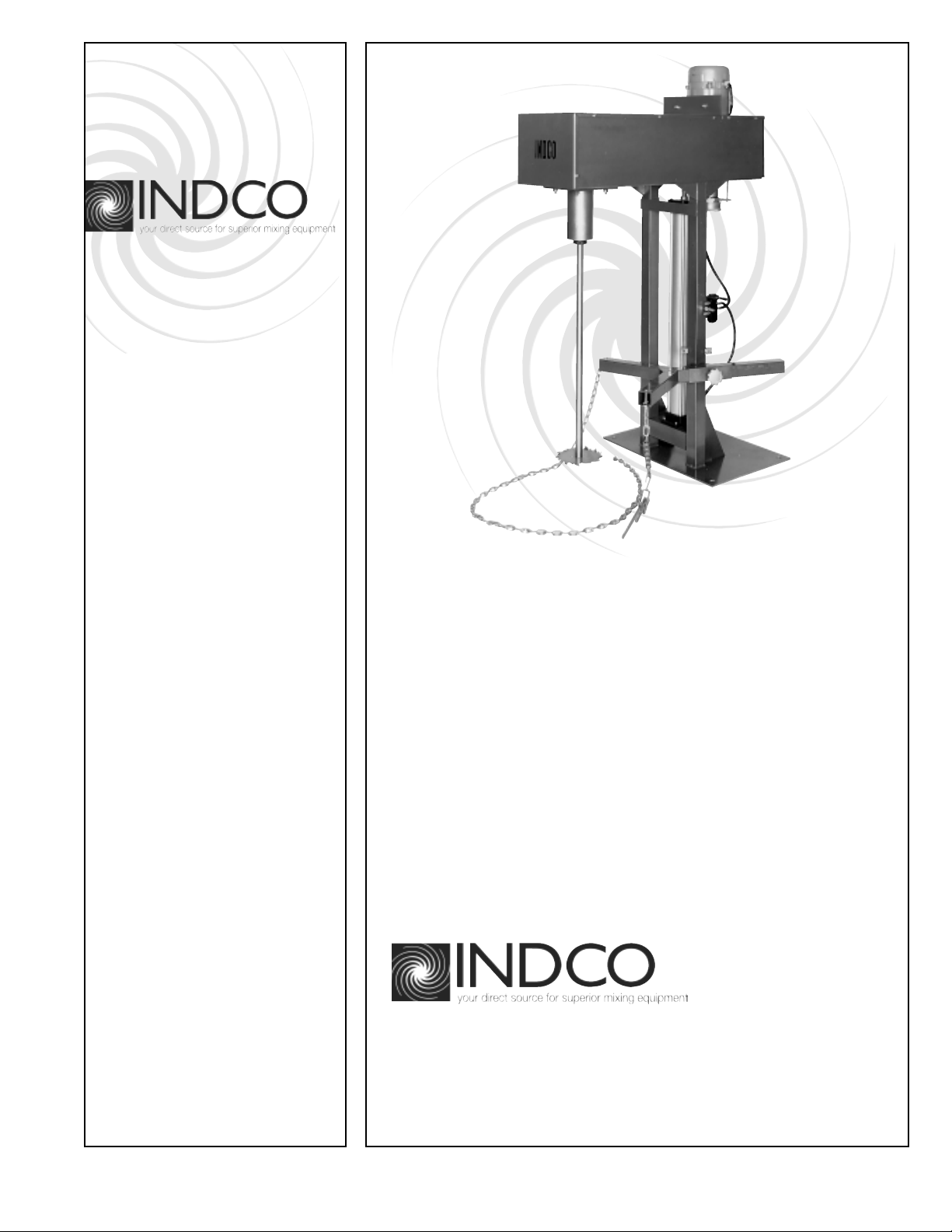
Operation
page 4 of 11
mechanical
speed
control
hand-wheel
lift cylinder
control valve
blade bolt
container
holder
Operation, continued
INDCO, Inc. M-M-30118 mixer manual HS-5 date: 3/8/05
Maintenance
Maintaining your mixer is not difficult if you follow these
guidelines:
• Keep the mixer clean.
• Check all wiring on a regular basis and repair as needed.
• Unit fails to start: Check power source to unit, check
-and/or- reset breaker. If problem continues, disconnect
power and have a qualified person make proper repairs.
• Ensure the dispersion blade is fastened securely to the
shaft.
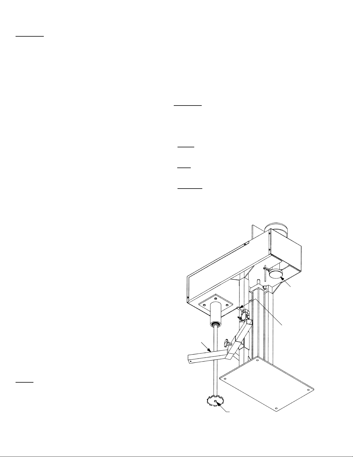
design A
(top view)
Blade Rotation:
Ensure the mixer shaft will rotate in a clock-wise direction,
looking downward into the container. Care must be taken
to ensure blade is rotating in the correct direction. Look for
arrow on blade or consult factory.
page 5 of 11
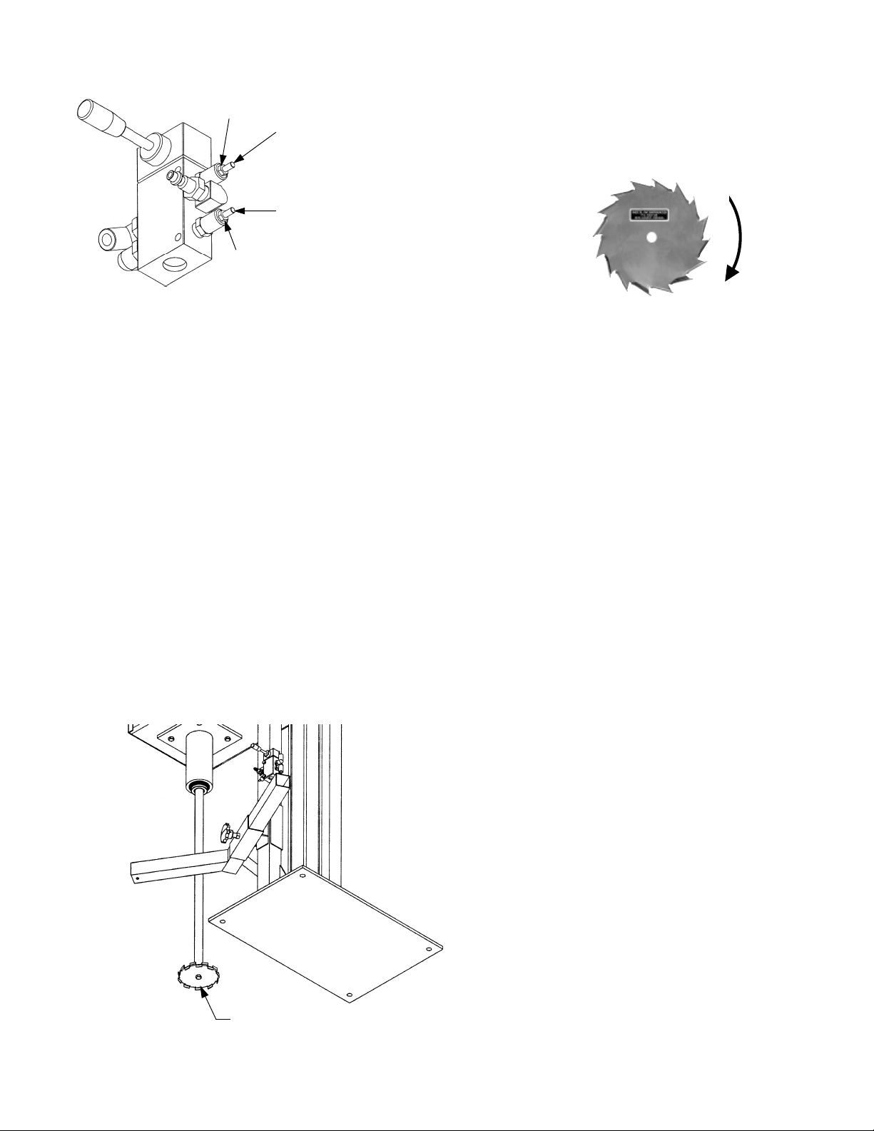
Blade Changing:
ENSURE POWER TO UNIT IS OFF OR DISCONNECTED!
Remove the bolt from the bottom of the shaft, remove and
replace the blade and replace the bolt.
blade bolt
Mechanical Variable Speed Drive
• Avoid using automotive chassis and other non-
interchangeable lubricants. Lubricated pulleys will stick
or freeze if not lubricated properly. The most frequent
cause is failure to run the drive through part of its range
at the time it is lubricated. The pulley must be lubricated
periodically and pulley adjustment opened and closed to
distribute the grease inside. Small amounts of grease
will do. Wipe excess off of belt faces.
• Check belt alignment. Misalignment will cause the belt
to overheat and wear rapidly.
• Watch for overload conditions. If the belt loops out or
squeals the drive is overloaded. This condition will
frequently exist during start-up but should not continue
for more than a few seconds. When starting up,
particularly if starting several times a day, try to start
up slowly by jogging the machine to bring the speed up
gradually.
• Excessive vibration will cause damage to all of the
equipment in the drive system. If any doubt exists as
to the safe levels of vibration a qualified person should
be called in to examine the drive.
• Use Loctite on set screws where necessary to prevent
screws from backing out due to vibration in machine.
• Air Valve ~ Cylinder speed control adjustment:
Air flow adjusting screw:
- screw in until desired
lowering speed is
obtained.
Air flow adjusting screw:
- screw out until desired
lifting speed is obtained.
Once desired raise &
lowering speeds are
obtained, tighten lock-nuts.
lock-nut
lock-nut
Operation, continued Maintenance, continued
Table of contents


