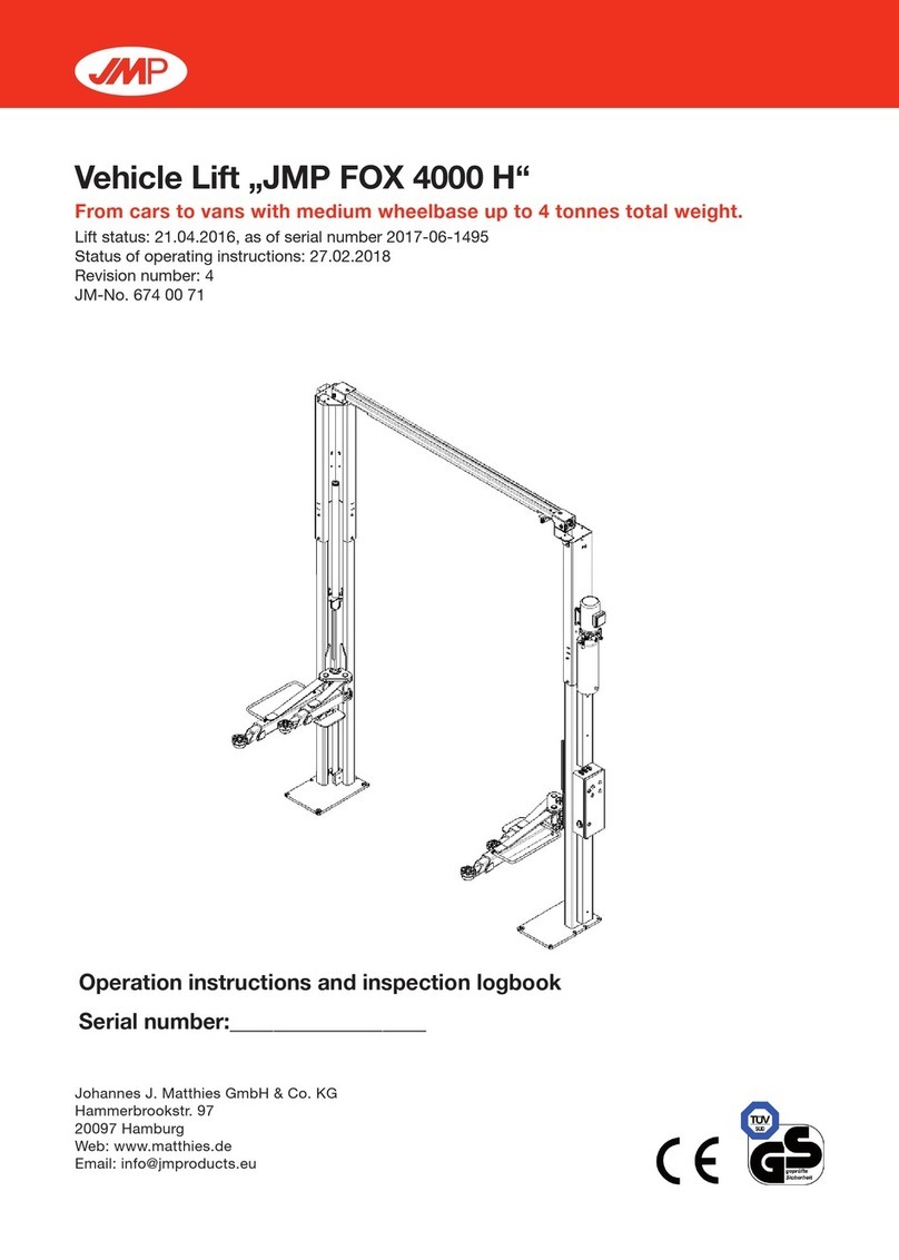
INDCO PSA84-BP User manual

OWNERSMANUAL
Mixer Lift Stand
Air Cylinder Lift
tablEOFCONTENTS:
PSA84-BP - STATIONARY............................................2
PSA84 - PORTABLE “X” BASE ....................................3
PSA-BT-BP - STATIONARY ..........................................4
PSA-DL-BP - STATIONARY..........................................4
PSA-BT - PORTABLE “TOTE” BASE............................5
PSA-DL - PORTABLE “TOTE” BASE............................5
Parts List ......................................................................6
4040 Earnings Way •NEW ALBANY, IN 47150•
P: 812-941-5954
INDCO, Inc. • M-M-30130 Lift Stand -Air manual • 2/5/13 • Page 1 of 6
Warranty
Our products are guaranteed against
defective materials and workmanship,
we will repair or replace such items
as may prove defective at our option.
Warranty period is one year on items
manufactured by INDCO, except for
the MixMaster Series Shakers which
carries a two year warranty. On items
not manufactured by INDCO, the
manufactures warranty applies. All
component parts of our products are
covered by this warranty, except for
normal wear items such as belts or
impellers. We cannot be responsible
for damage or abuse to equipment
caused by improper installation or
operation. Warranties can also be
voided by unauthorized disassembly
of equipment. For warranty repairs,
equipment is returned to INDCO at
the customer’s expense; we will repair
and return to customer at our expense.
Under no circumstances will we allow
labor charges or other expense to repair
defective merchandise. This warranty
is exclusive and is in lieu of all other
warranties, whether express or implied.
INDCO shall not be liable for any other
damages, whether consequential,
indirect, or incidental, arising from the
sale or use of its products.
Mixer
Stands
-Air Lift-

PSA84-BP
Stationary Lift Stand
FEatuRES:
•Constructed from heavy gauge plate and square tubing, carbon
steel - painted.
•Capacity to hold up to 200 lbs.
•Air cylinder actuation - 36” travel. 10cfm @ 40 psi required.
OpERatiON:
•Height adjusts with a 3-position air control valve. This valve is
spring centered and rests in the center “off” position.
cautiON:
After the air line is installed and before operating this machine for
the rst time, move the lift control valve to the downward position.
This will “charge” the air cylinder and prevent surging when the lift
control valve is moved to the upward position.
•Air Valve - Cylinder speed control adjustment:
INDCO, Inc. • M-M-30130 Lift Stand -Air manual • 2/5/13 • Page 2 of 6
up “raise” position
center “off” position
down “lower” position 3-position
air control
valve
Air ow adjusting screw:
close approx. ½-turn until
desired lowering speed is
obtained.
Air ow adjusting screw:
open approx. ½-turn un-
til desired lifting speed is
obtained.
Once desired raise &
lowering speeds are
obtained, tighten locking
nuts.
lock-nut
lock-nutjoystick
mixer mount
max. 81”
min. 45”
4”
7.75”
12” x 12” base
• 1/4” plate
FOUR - 9/16” x 1” slots
• 10” centers
mixer
mount plate
& slide-tube
84.25”
overall
height
air
cylinder
3-position
control
valve

PSA84
Portable Lift Stand
- ”X” Base -
FEatuRES:
•Accomdates containers up to 48” diameter.
•Constructed from heavy gauge plate and square tubing, carbon
steel - painted.
•Capacity to hold up to 200 lbs.
•Units supplied with four swivel casters, two with brakes.
•Air cylinder actuation - 36” travel. 10cfm @ 40 psi required.
OpERatiON:
•Height adjusts with a 3-position air control valve. This valve is
spring centered and rests in the center “off” position.
cautiON:
After the air line is installed and before operating this machine for
the rst time, move the lift control valve to the downward position.
This will “charge” the air cylinder and prevent surging when the lift
control valve is moved to the upward position.
aSSEmbly - “x” baSE:
1, Slide tube assembly over “stub”.
2. Mount 12” x 12” up-right base onto portable “X” base with (4)
1/2” bolts, washers and nuts.
INDCO, Inc. • M-M-30130 Lift Stand -Air manual • 2/5/13 • Page 3 of 6
mixer mount
max. 88”
min. 52”
(assembled)
4”
7.75”
mixer
mount plate
& slide-tube
90.5”
overall height
(assembled)
air
cylinder
3-position
control
valve
(4) caster, swivel
12” x 12”
baseplate
(2) 3.5”
bolts
(2) 1.5”
bolts
40”
7.5”
30”
slide tube ass’y over “stub”.
up “raise” position
center “off” position
down “lower” position 3-position
air control
valve

PSA-BT-BP
Stationary Lift Stand
FEatuRES:
•Accomdates containers up to 48” diameter.
•Constructed from heavy gauge plate and square tubing, carbon
steel - painted.
•Capacity to hold up to 150 lbs.
•Air cylinder actuation - 48” travel. 10cfm @ 40 psi required.
OpERatiON:
•Height adjusts with a 3-position air control valve. This valve is
spring centered and rests in the center “off” position.
cautiON:
After the air line is installed and before operating this machine for
the rst time, move the lift control valve to the downward position.
This will “charge” the air cylinder and prevent surging when the lift
control valve is moved to the upward position.
•Air Valve - Cylinder speed control adjustment:
INDCO, Inc. • M-M-30130 Lift Stand -Air manual • 2/5/13 • Page 4 of 6
up “raise” position
center “off” position
down “lower” position 3-position
air control
valve
mixer mount
max. 98”
min. 50”
4”
7.75”
18”
extention
96.25”
overall
height
mixer
mount plate
& slide-tube
air
cylinder
3-position
control
valve
12” x 12” base
• 1/4” plate
FOUR - 9/16” x 1” slots
• 10” centers
PSA-DL &
PSA-DL-BP
mixer
mount plate
& slide-tube
Air ow adjusting screw:
close approx. 1/2-turn until
desired lowering speed is
obtained.
Air ow adjusting screw:
open approx. 1/2-turn until
desired lifting speed is ob-
tained.
Once desired raise &
lowering speeds are
obtained, tighten locking
nuts.
lock-nut
lock-nut
joystick

PSA-BT
Portable Lift Stand
-”Tote” Base-
FEatuRES:
•Accomdates containers up to 48” diameter.
•Constructed from heavy gauge plate and square tubing,
carbon steel - painted.
•Capacity to hold up to 150 lbs.
•Units supplied with two swivel casters, two rigid casters
and two with brakes.
•Air cylinder actuation - 48” travel. 10cfm @ 40 psi
required.
cautiON:
After the air line is installed and before operating
this machine for the rst time, move the lift
control valve to the downward position. This will
“charge” the air cylinder and prevent surging
when the lift control valve is moved to the
upward position.
OpERatiON:
•Height adjusts with a 3-position air control valve. This
valve is spring centered and rests in the center “off”
position.
aSSEmbly “tOtE” baSE:
•Place up-right tube assembly onto the portable
base.
•Mount 1/2” x 12” up-right base to portable
base with 1/2” bolts, washer and nuts.
(4-pieces).
INDCO, Inc. • M-M-30130 Lift Stand -Air manual • 2/5/13 • Page 5 of 6
up “raise” position
center “off” position
down “lower” position 3-position
air control
valve
mixer mount
max. 104”
min. 56”
(assembled)
4”
7.75”
18”
extention
(4) casters
50”
inside
width
32”
102.25”
overall height
(assembled)
mixer
mount plate
& slide-tube
air
cylinder
3-position
control
valve
(2) 3.5”
bolts
(2) 1.5”
bolts
12” x 12”
baseplate

Parts List - Air Lift Stands
INDCO, Inc. • M-M-30130 Lift Stand -Air manual • 2/5/13 • Page 6 of 6
“X” Base “Tote” Base
1a
12a
9
9
15 9
12b
1b
12a 12b
10
9
15
15
2
6
6
3
4
3
5
8
9
itEm DEScRiptiON paRt NO. Qty.
• “X” Base with Casters (complete) N-X-LIFT-BASE 1
• “Tote” Base with Casters (complete) N-PSBT-BASE 1
1a. Air Cylinder - 36” ( models: PSA84-BP & PSA84 ) HDW-4X36 1
1b. Air Cylinder - 48” ( models: PSA-BT-BP & PSA-BT ) HDW-4X48 1
2. Spool Valve, 3-position HDW-E2181-1000 1
3. Mufer for Spool Valve - brass HDW-SPCMUF 2
4. Street elbow, 1/4” - brass HDW-2202P-4-4 1
5. Quick connect tting, male, 1/4” - steel HDW-1/4-M-QCPLUG 1
6. Push connect, 90° elbow - 3/8” tube x 1/4”MNPT HDW-W369ML-6-4 2
7. Push connect, 90° elbow - 3/8” tube x 1/2”MNPT (not shown) HDW-W369ML-6-8 2
8. Tubing, 3/8” x 60” long HDW-EB-64-0500 1
9. Caster, swivel - 3” dia. wheel HDW-4X618 2 ~ 4
10. Caster, rigid - 3” dia. wheel HDW-4X622 2
11. Caster brake kit (not shown) HDW-4X698 2
12a. short Bolt, hex-head - 1/2”-13 x 1.5” N-HARDWARE 2
12b. long Bolt, hex-head - 1/2”-13 x 3.5” N-HARDWARE 2
13. Flat washer - 1/2” (not shown) N-HARDWARE 4
14. Lock washer - 1/2” (not shown) N-HARDWARE 4
15. Nut - 1/2”-13 N-HARDWARE 4
This manual suits for next models
5
Table of contents
