INDELAC CONTROLS NEMA 4 User manual

Electric Fail-Safe Device
Battery Backup System
Installation, Operation & Maintenance
Manual
For Use with:
24vdc Units
10 & 30 Amp Units
TELEPHONE: +1-859-727-7890
TOLL FREE: +1-800-662-9424
FAX: +1-859-727-4070
SHIPPING ADDRESS: 6810 POWERLINE DR.-FLORENCE, KY. 41042
For a digital copy of this manual, access to training videos, access to 3D product renderings,
or to request additional support
VISIT OUR WEBSITE AT WWW.INDELAC.COM
REVISED: OCT 2021
Electric Fail-Safe Device Installation, Operation & Maintenance Manual, 3A
Page 2
INTRODUCTION:
Thank you for selecting Indelac Controls, Inc. (ICI) for your UPS / Battery Backup System needs. We at ICI are
proud of our products and feel confident they will meet or exceed your expectations of quality and reliability.
Every precaution has been taken to insure that your equipment will arrive undamaged; however, accidents do
occur. Therefore, the first thing you must do upon receipt of your package is to inspect it for damage. If the
box is damaged there is a possibility that the equipment inside the box may be damaged as well. If this is the
case YOU MUST FILE A CLAIM with the delivering CARRIER. All shipments are F.O.B. our factory and it is
YOUR RESPONSIBILITY to file a claim for damages.
NOTE: ICI’S ELECTRIC FAIL-SAFE DEVICE MAY BE USED WITH OTHER BRANDS
OF ELECTRIC ACTUATORS - ACTUATOR TERMINAL CONNECTIONS WILL NOT
BE THE SAME. CONTACT SALES TO VERFY APPLICATION FIT.
STORAGE:
If the Fail-Safe Device is scheduled for installation at a later date:
1. Store off the floor protect with unsealed cover allowing for side and bottom ventilation. In the
event that the unit is going to be stored where there is insufficient temperature control internal
heaters must be installed and energized to protect the unit from condensation and extreme
temperature variations.
2. Store in a climate controlled building.
3. Store in a clean and dry area.
4. See the Maintenance Section in this Manual for Proper Care of the Battery.
FOR FUTURE REFERENCE RECORD:
1. Fail-Safe model number
2. Fail-Safe enclosure type NEMA 4_____, NEMA 4X_____, NEMA 7_____.
3. Fail-Safe output Voltage
4. Fail-Safe serial number
5. Date of installation Put into operation
Electric Fail-Safe Device Installation, Operation & Maintenance Manual, 3A
Page 3
TABLE OF CONTENTS:
PRODUCT DESCRIPTION: 4
UNIT SPECIFICATIONS: 5
WIRE SIZING AND LENGTHS: 5
CUSTOMER ELECTRICAL CONNECTIONS &WIRING DIAGRAMS: 6
SET-UP AND OPERATION: 9
BATTERY RUN TIMES: 11
MAINTENANCE: 11
BATTERY MAINTENANCE LOG: 12
FUSES &DESCRIPTION: 13
SPARE PARTS: 14
NEMA 7ENCLOSURES: 15
MANUAL REVISIONS: 15
TROUBLESHOOTING: 16
Electric Fail-Safe Device Installation, Operation & Maintenance Manual, 3A
Page 4
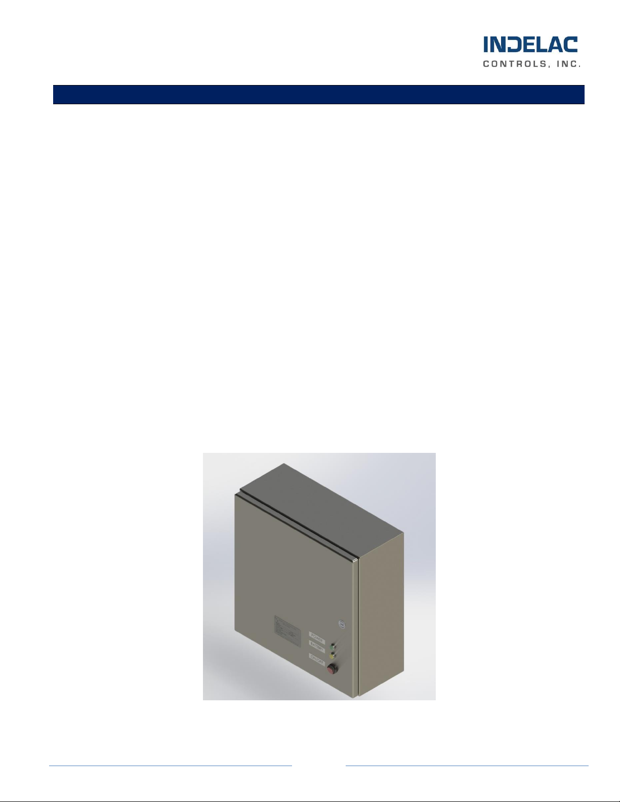
PRODUCT DESCRIPTION:
The Indelac Controls DC Electric Fail-Safe Device provides battery backup power to your actuator in the
unlikely event that the Factory or Facility Mains Power should go down. These devices are designed to
seamlessly supply 24vdc battery standby power to power your 24vdc actuator. The battery supplies an
internal Backup Module that supplies backup DC to run the actuator to the user wired Fail Position when
the Mains Power fails. When normal Mains Power is present, it powers the actuator and provides a
maintenance charge to the backup batteries. When the Mains Power fails or drops out momentarily, the
Backup Module will automatically switch over to battery power and supply a constant 24vdc to the actuator.
When the Mains Power comes back online, the Backup Module will immediately transfer Mains Power back
to the actuator and proceed to re-charge and maintain the batteries.
Indelac provides these DC Fail Safe Devices in NEMA 4, NEMA 4X or NEMA 7 enclosures to provide 10 or
30 Amps of output power. Each Fail-Safe Device is designed to supply the actuator’s continuous Full Load
Ampere draw to drive the Actuator to the Fail-Safe position. When selecting the Fail-Safe Device to back
up your actuator power, 10 Amps or 30 Amps is the MAXIMUM current output to the load. Therefore, the
Locked Rotor Amps or Start-Up Current of the Actuator needs to be figured into the maximum 10 Amps or
30 Amps output.
The Fail-Safe Device will float charge the on-board Sealed Lead Acid Batteries when Mains Power is ON.
Depending on the size & age of the batteries used in the Fail-Safe Device, battery charge time can vary
from hours to overnight for a full charge.
Optional features, such as Emergency Disconnect Switches, Internal Heaters and Internal Relays to run
more than 1 actuator to Fail Position may be ordered –Consult the Factory for available SPECIAL
Options.
24vdc 10 Amp NEMA 4X Version Shown

Electric Fail-Safe Device Installation, Operation & Maintenance Manual, 3A
Page 5
UNIT SPECIFICATIONS:
Enclosure rating: NEMA 4; NEMA 4X & NEMA 7
Operating Voltages: 24vdc
10A Fail-Safe Output Fuse: 10 Amp, 250VAC, Slow Blow, 5x20mm
30A Fail-Safe Output Fuse: 40 Amp, 32VDC, Slow Blow, MEGA Cartridge
Light Indicators: Green = Power; Yellow = Battery; Red = Mains ON
The following chart shows the Standard Fail-Safe Device Part Numbers and the related Specifications for
each unit. There are 2 –12vdc batteries in each Fail-Safe Device.
Part Number
Output
Voltage
Current
Output
Output
(Watts)
Battery
AHr
NEMA
Rating
Enclosure Dimensions
Weight
–lbs.
322-10E-CS4
24
10A
240
2 - 5
4
12”L x 12”W x 6”D
24
322-10E-SS4X
24
10A
240
2 - 5
4X
12”L x 12”W x 6”D
26
322-10E-AL7
24
10A
240
2 - 5
7
12”L x 12”W x 6”D
86
322-30E-CS4
24
30A
720
2 - 14
4
16”L x 16”W x 6”D
63
322-30E-SS4X
24
30A
720
2 - 14
4X
16”L x 16”W x 6”D
64
322-30E-AL7
24
30A
720
2 - 14
7
18”L x 18”W x 6”D
335
** NEMA 4X Enclosures are Stainless Steel.
WIRE SIZING AND LENGTHS:
Indelac recommends the Installer follow the wire gauge chart shown below when connecting the Fail-Safe
Device to the actuator. The Fail-Safe Device should be mounted at the shortest distance possible to the
actuator to assure best possible performance. Indelac DOES NOT recommend that the Fail-Safe Device
be mounted any further than 50 feet from the actuator.
24vdc Fail-Safe Device
16
14
12
10
8
Amperage
MAXIMUM Distance in Feet From Fail-Safe
10 Amp
10
20
30
50
70
30 Amp
-
-
10
15
25
WIRE GAUGE
WARNING!
WIRING MUST CONFORM TO ALL STATE AND LOCAL ELECTRICAL WIRING CODES.
THIS DEVICE SHOULD BE INSTALLED BY A LICENSED ELECTRICIAN.
IMPROPER POWER CONNECTION CAN RESULT IN DAMAGE TO THE COMPONENTS OR SERIOUS
INJURY TO THE INSTALLER.
VERIFY THAT ALL WIRES ARE DE-ENERGIZED BEFORE MAKING ELECTRICAL CONNECTIONS!

Electric Fail-Safe Device Installation, Operation & Maintenance Manual, 3A
Page 6
ELECTRICAL CONNECTIONS & WIRING DIAGRAMS:
All wiring is to be completed through the conduit openings using the appropriate conduit –Refer to your
local electrical codes. Open the Fail-Safe Device door by turning the latch counter-clockwise using a flat
head screwdriver. To Open the Door on the NEMA 7 enclosure, ALL of the outer Door bolts need to be
removed before Opening at the hinge. Connect the Main Power to the Fail-Safe Device & connect the Fail-
Safe Device to the actuator per the appropriate wiring diagram below. Assure that the power wires are DE-
ENERGIZED!
Mount the Fail-Safe Device to a solid surface using the appropriate hardware. These units are heavy and
using hardware that is not appropriate or too small may cause the Fail-Safe Device to separate from its
mounting and become damaged. See the Unit Specifications Section for dimensions and weights.
NOTE: Two (2) conduit openings are supplied in the cabinet housing of the Fail-Safe Device.
One opening is for the incoming DC power wires and the other is for the Outgoing Power wires
to the actuator. All wires are to be securely tightened into the Customer Connections Terminal
Block.
30 Amp NEMA 7 Version Shown, Internal Connections View
CAUTION: Make sure that the wires are DE-ENERGIZED BEFORE making any electrical
connections. Serious damage to the components or serious injury/death may occur.
Also verify that the proper voltage and wiring is being connected to the Fail-Safe Device and
matches the required input of BOTH the Device and the Actuator.
Customer Connections
Terminal Block
Backup Module
NOTE: For all wiring, make sure the connectors and wires are fully seated after making all wiring
Connections and Screw Terminals are tight!
Electric Fail-Safe Device Installation, Operation & Maintenance Manual, 3A
Page 7
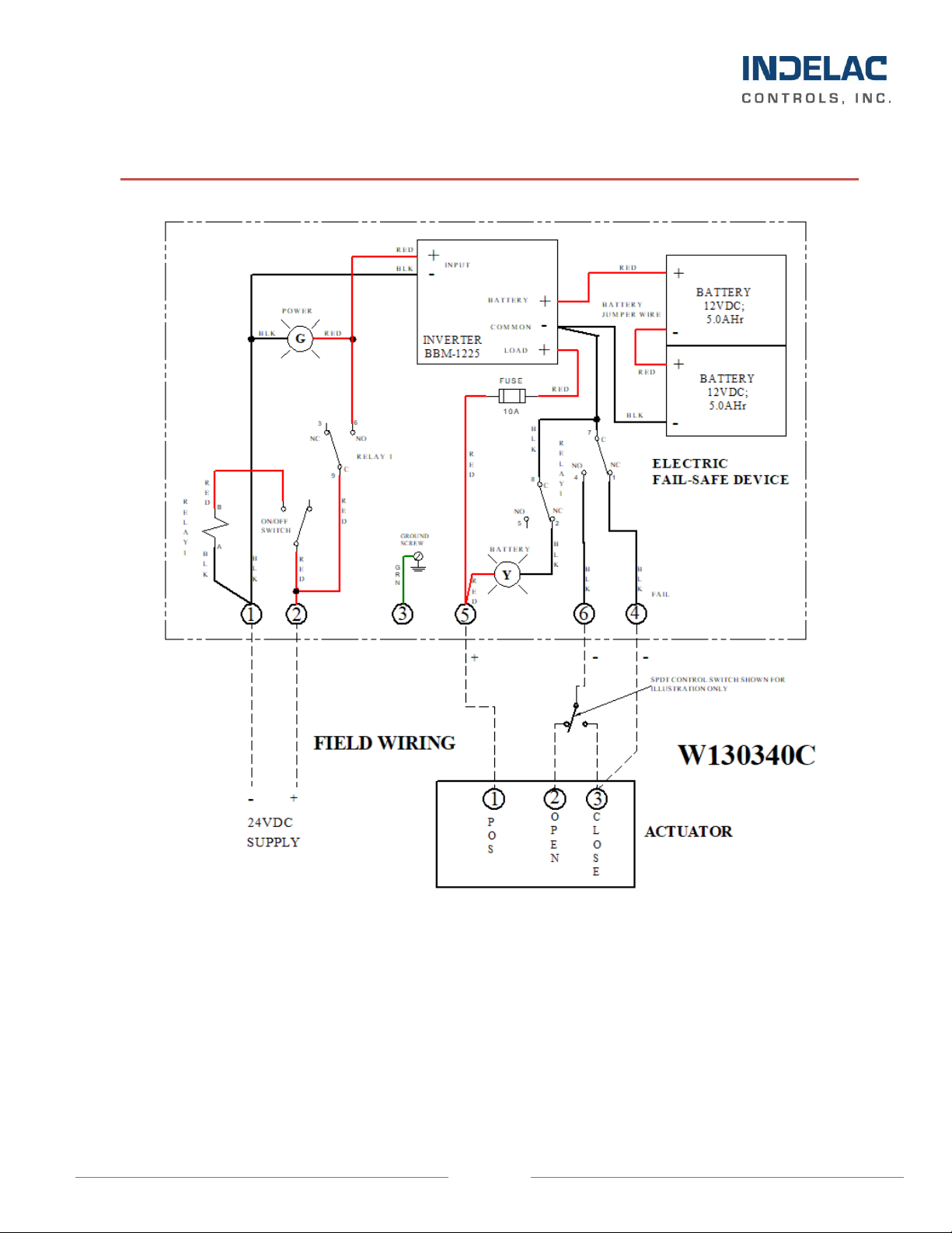
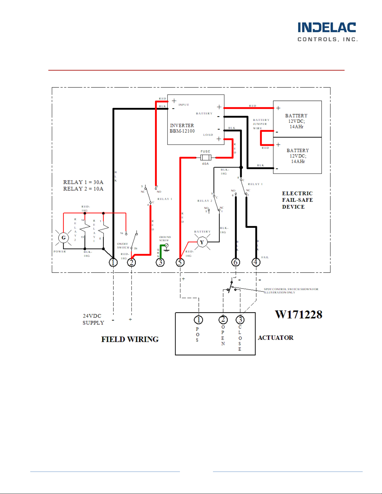
10 AMP 24VDC FAIL-SAFE DEVICE WIRING/CONNECTION DIAGRAM
Wiring diagram shows the Actuator wired for FAIL CLOSE –the Fail Terminal #4 is wired to the CLOSE Terminal on the
Actuator. When the incoming Mains Power Fails or is shut OFF, Terminal #4 will be energized Negative (-) to drive the
Actuator to the CLOSE Position. This Terminal #4 may also be connected to the OPEN Terminal on the Actuator to
drive the Actuator OPEN when power fails.
Electric Fail-Safe Device Installation, Operation & Maintenance Manual, 3A
Page 8
30 AMP 24VDC FAIL-SAFE DEVICE WIRING/CONNECTION DIAGRAM
Wiring diagram shows the Actuator wired for FAIL CLOSE –the Fail Terminal #4 is wired to the CLOSE Terminal on the
Actuator. When the incoming Mains Power Fails or is shut OFF, Terminal #4 will be energized Negative (-) to drive the
Actuator to the CLOSE Position. This Terminal #4 may also be connected to the OPEN Terminal on the Actuator to
drive the Actuator OPEN when power fails.
Electric Fail-Safe Device Installation, Operation & Maintenance Manual, 3A
Page 9
FAIL-SAFE SET-UP & OPERATION:
SET-UP:
When the Fail-Safe Device is mounted and all wiring has been completed to the proper wiring diagram, the
final Set-Up steps can be completed. The Fail-Safe unit is internally wired and ready to be enabled.
1) If the front panel door to the Fail-Safe Device is not open, open it using a flat head screwdriver to
unlock the door latch. On the NEMA 7 Device, you will need to remove ALL of the outer door bolts
to open the door!
2) Check all wiring connections again and verify that all wiring, relays and terminals are tight.
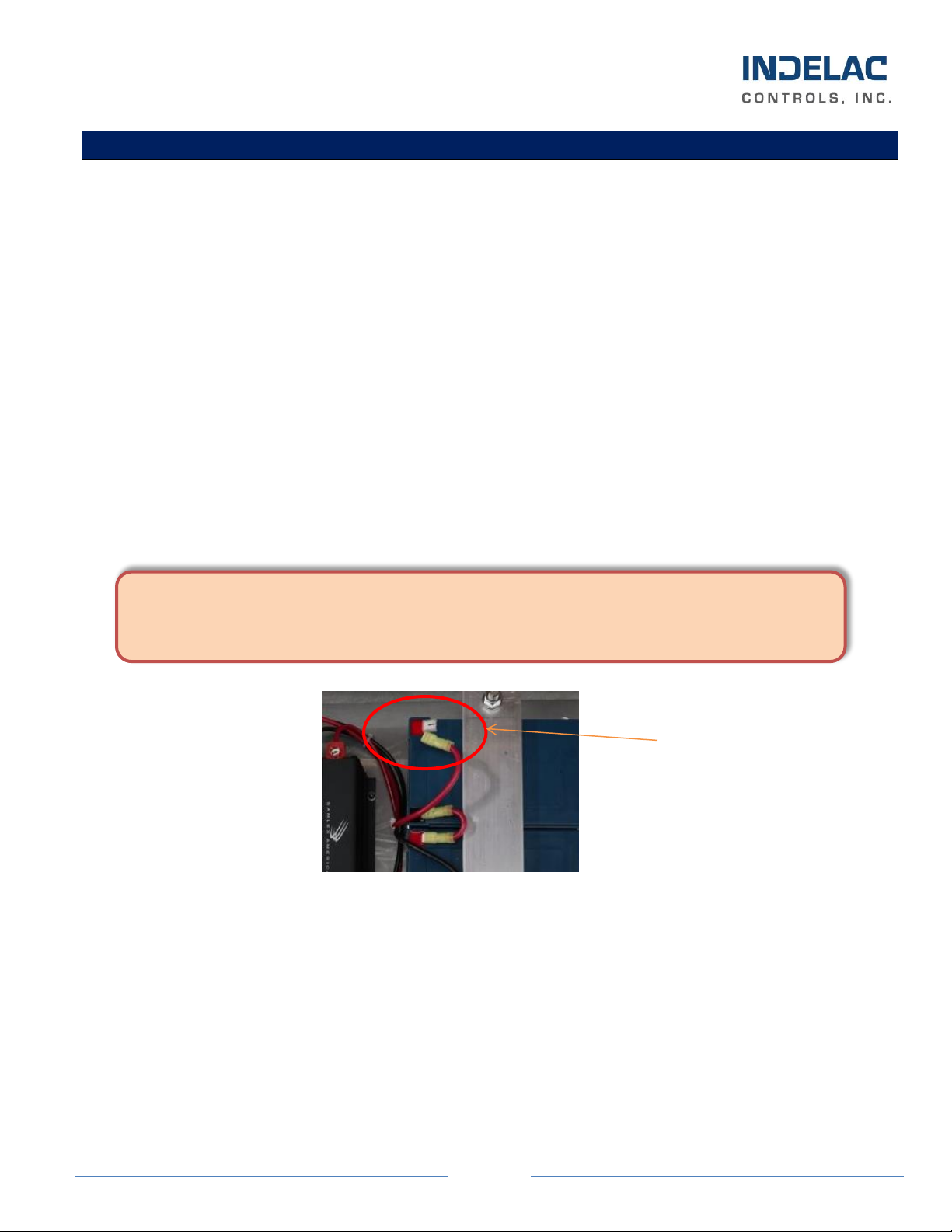
3) Plug the battery RED lead into the RED Battery Terminal. This has been removed to ship the Fail-
Safe Device.
4) At this time, the Fail-Safe Device has power to the output terminals and the unit is LIVE!
CAUTION: Depending on the position of the Actuator when the set-up was completed, it may
start to move.
Battery Connection
5) Apply Incoming Mains Power to the Fail-Safe Device and turn ON the front panel Power Switch.
CAUTION: This will apply Mains Power to the Actuator and depending on the position of the
Actuator, it may move again.
6) When the Front Door Power Switch is turned ON, the Front Door Power Switch should illuminate
Red, the Green POWER Light should turn ON to indicate that the Fail-Safe Device is Enabled.
7) Close and Latch (or Bolt) the Front Door securely Closed.
CAUTION: WHEN ENABLING THE FAIL-SAFE DEVICE AND APPLYING MAINS
POWER TO THE UNIT, LIVE VOLTAGE IS PRESENT! TAKE GREAT CARE NOT TO
TOUCH THE POWER TERMINAS - SERIOUS INJURY OR DEATH MAY OCCUR!
Install RED Lead
onto RED Battery
terminal
Electric Fail-Safe Device Installation, Operation & Maintenance Manual, 3A
Page 10
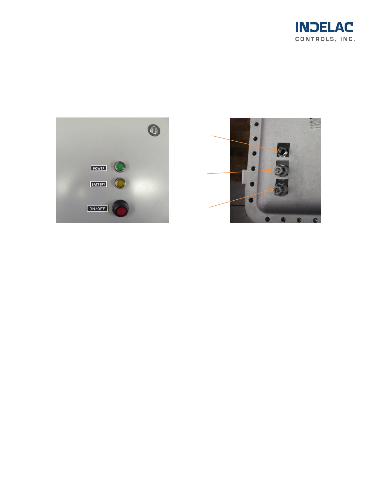
OPERATION:
When the Fail-Safe Device is in the Normal Mode, the Red Front Door Power Switch will be illuminated
Red and the Green POWER Light will be ON for the NEMA 4 & NEMA 4X. On the NEMA 7 Version,
there will NOT be a Red Light on the ON/OFF Switch. If the Green POWER Light turns OFF, there is a
blown output fuse and the actuator will not run.
NEMA 4 & 4X NEMA 7
The Fail-Safe Device is designed so that when the Mains Power Fails, or the Front Door Power Switch is
turned OFF, the Red Power Switch Light and Green POWER Light will turn OFF and the Yellow
BATTERY Light will turn ON. This indicates to the User that the Fail-Safe Device is running on Battery
Power and should deliver Power to the User selected Fail Terminal on the Actuator and the Actuator will
drive to that position. This power transfer takes only milliseconds and happens automatically without any
User interface.
When the Mains Power returns, the Fail-Safe Device will automatically switch the Battery power OFF and
enable Mains Power back to the Actuator. When this happens, the Yellow BATTERY Light will turn OFF
and the Green POWER Light and Red Switch Light will both turn back ON. At this time, the battery will
go into a FLOAT charge mode.
If the Green POWER Light does NOT turn ON, but the Mains Power has been checked and is good to the
Fail-Safe Device, it is possible that the internal Output Fuse has blown. See the Maintenance Section for
how to check this fuse.
If the Mains Power has shut down and the Yellow BATTERY Light does not come ON and there is NO AC
Power to the Actuator, the internal Output Fuse may have blown or the Power Inverter was damaged. See
the Maintenance Section for how to check these devices.
POWER
Light
BATTERY
Light
ON/OFF
Switch
Electric Fail-Safe Device Installation, Operation & Maintenance Manual, 3A
Page 11
BATTERY RUN TIMES:
Each of the Fail-Safe Devices has a minimal run time depending on the load and charge of the battery.
These Devices are calculated to have a continuous battery run time of 10 to 12 minutes under full capacity
load. For example, the 10 Amp Device will run under battery power for 12 minutes under a 10 Amp
continuous load draw. Therefore, if the load draw is less than the Device’s current rating, the battery run
time will be longer. The Fail-Safe Device is designed to run the Actuator to the wired FAIL position and
hold there until Mains Power comes back ON. All of the Indelac Actuators will complete an OPEN or
CLOSE cycle in less than the 10 to 12 minutes under full load with a fully charged battery.
If longer battery run times are required, contact Indelac Controls for special order Fail-Safe Designs.
MAINTENANCE:
After proper installation, the Fail-Safe Device requires no actual maintenance. This unit should operate for
4-5 years on the original battery as long as the Mains Power is applied and the power is ON to maintain the
internal battery charger. However, we do recommend a periodic battery check to assure that the battery is
retaining a charge. This can be accomplished by using an Electrical DC Meter to measure the battery
voltage. Measure between the RED Lead of the top battery and the BLACK Lead of the other battery. This
voltage should measure between 22 to 25vdc. If this voltage is too low, try allowing the batteries to charge
with the Mains Power ON. If after this charge (usually overnight), the batteries are still low, the batteries
need to be Replaced!
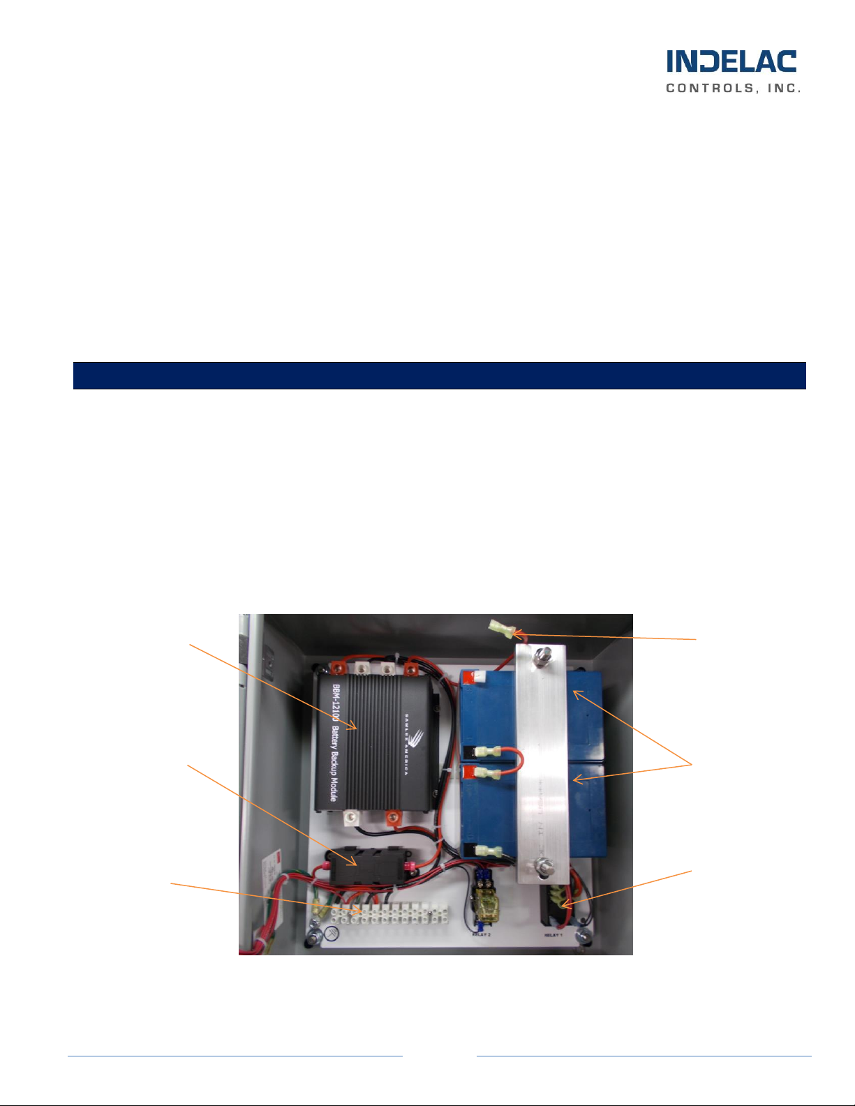
Internal View of 30A NEMA 4 Fail-Safe Device
Batteries
Backup Module &
Battery Charger
RED Battery
Lead
Transfer
Relay
Customer
Connections
Terminal Block
Output Fuse,
MEGA Style

Electric Fail-Safe Device Installation, Operation & Maintenance Manual, 3A
Page 12
Battery Measurement Test Points
The following chart has been provided to log the periodic maintenance battery checks:
BATTERY MAINTENANCE LOG
Date
Checked By:
24vdc Measurement
RED Meter Lead
BLACK Meter Lead
Measure on DC Volts
22-25vdc

Electric Fail-Safe Device Installation, Operation & Maintenance Manual, 3A
Page 13
MAINTENANCE (con’t.):
The Fail-Safe Device can be stored for 4-6 months in the “no load” condition before the battery will need to
be recharged. If these Units are stored longer than this before being installed, the customer needs to
implement a program to charge these batteries for 8-10 hours every 4 months. This will maintain the
batteries until installation. If these batteries are NOT maintained, they will be too low or dead and not
operate when installed.
If the Fail-Safe Device is installed, the Mains Power needs to be turned ON to maintain the battery. The
internal trickle charger will maintain the battery for use when needed. If the Mains Power is shut OFF or
the Mains Power Breaker has tripped, the Fail-Safe will be operating under battery power an illuminates the
Front Door Yellow Light. This will drain the battery more quickly.
To charge a low battery, make sure the Mains Power and Front Door Power Switch is ON. Once the
batteries charge measures below 16vdc, they may not take a charge due to internal cell damage. Even if the
batteries do take a charge, they may be unreliable and SHOULD be REPLACED!
OUTPUT FUSE (smaller fuse –10A Version):
When the Green POWER Light on the Front Door of the 10A Fail-Safe Device does NOT turn ON when
the Mains Power or Battery Power is active, the Output Fuse may be blown. This Fuse is a 10A Slow Blow
Cartridge 5x20mm Fuse rated for 250VAC. Indelac Part # 46039.
To check the Fuse on the 10A Devices, follow the below steps:
1) Remove ALL power from the Fail-Safe Device and remove the fuse from the holder.
2) Using an Electrical Meter, check the continuity of the fuse.
3) If it is blown, replace with the proper fuse value as listed above.
4) Turn the Mains Power back on and check to see if the Front Door Green Light is ON.
5) If the Green Light is still not ON, there may be a problem with the Backup Module or Battery and
the unit will need to be returned to Indelac for Service.
ATTENTION: IF THE BATTERY IS NOT PROPERLY MAINTAINED,
THE BATTERY WILL BE TOO LOW TO DRIVE THE ACTUATOR TO
THE FAIL POSITION WHEN NEEDED!

Electric Fail-Safe Device Installation, Operation & Maintenance Manual, 3A
Page 14
OUTPUT FUSE (larger fuse –30A Version):
When the Green POWER Light on the Front Door of the 30A Fail-Safe Device does NOT turn ON when
the Mains Power or Battery Power is active, the Output Fuse may be blown. This Fuse is a 40A Slow Blow
Cartridge MEGA Fuse rated for 32VDC. Indelac Part # 46069.
To check the Fuse on 30A Devices, follow the below steps:
1) Remove ALL power from the Fail-Safe Device and remove the fuse from the holder.
2) Using an Electrical Meter, check the continuity of the fuse.
3) If it is blown, replace with the proper fuse value as listed above.
4) Turn the Mains Power back on and check to see if the Front Door Green Light is ON.
5) If the Green Light is still not ON, there may be a problem with the Backup Module or Battery and
the unit will need to be returned to Indelac for Service.
SPARE PARTS:
The Indelac Fail-Safe Devices are maintenance free units. The only parts that are field replaceable are the
internal 12vdc batteries and fuses. A list of the batteries and their part numbers are shown below. The fuse
part numbers are listed in the Fuse Descriptions in the Maintenance Section. When calling for spare parts,
please include your Model Number, Serial Number, Description and Date of Installation.
If the unit is not working and it is suspected that there is a failure in the Backup Module, the Fail-Safe
Device will need to be sent back to Indelac for repair and calibration.
Spare Part
Indelac Part
Number
Battery, 5AHr (x’s 2)
32006
Battery, 14AHr (x’s 2)
32015
Electric Fail-Safe Device Installation, Operation & Maintenance Manual, 3A
Page 15
NEMA 7 ENCLOSURE, GENERAL:
In general, operation and maintenance of a NEMA 7 Fail-Safe Device is no different than that of a NEMA 4
Unit. However, there are some precautions that must be followed.
1) DO NOT install in ambient temperatures that exceed 140 degrees F.
2) DO NOT under any circumstances remove the Fail-Safe cover while in a hazardous location when
the contacts are still live; this could cause ignition of hazardous atmospheres.
3) DO NOT under any circumstances use a NEMA 7 Fail-Safe Device in a hazardous location that
does not meet the specifications for which the Unit was designed. The Fail-Safe Device is clearly
tagged with the NEMA classification it was designed for.
4) When removing the cover, care must be taken not to scratch, scar or deform the flame path of the
cover or base of the Fail-Safe Device. This will negate the NEMA 7 rating of the enclosure.
5) When replacing the cover on a Fail-Safe Device, take care that the gasket is in place to assure the
proper clearance after the cover is secured. After securing the cover screws check the clearance
between the cover and the base - a .002” thick by 1/2” wide feeler gauge may not enter between the
two mating faces more than .125”.
6) All electrical connections must be to State and Local Codes and in accordance with the
specifications for which the unit is being used.
7) If the Unit has an internal heater, wait at least 45 minutes after removing power from the NEMA 7
Fail-Safe Device for cooling, before removing the cover.
*In the event maintenance is required, remove the Fail-Safe Device from the hazardous location
before attempting to work on it.
MANUAL REVISIONS
OCT 20,
2021
INITIAL RELEASE.

Electric Fail-Safe Device Installation, Operation & Maintenance Manual, 3A
Page 16
TROUBLESHOOTING AND FAQ’S
Many of the Troubleshooting Issues have been covered in the Operation and Maintenance Sections above.
SYMPTOM
PROBLEM
SOLUTION
Power Switch does NOT
illuminate “RED”.
Mains Power not ON or external
Breaker Tripped.
RED ON/OFF Switch in OFF
Position.
Reset external Breaker and Turn ON Mains Power.
Turn ON/OFF Switch to ON.
Green POWER Light does
NOT turn ON.
Mains Power has Failed & running
on Battery Power.
Internal Output Fuse is Blown.
Repair or Turn ON Mains Power.
Replace Output Fuse –see Maintenance for value.
Yellow BATTERY Light is
OFF.
Unit running on Mains Power.
Internal Output Fuse is Blown.
Battery is Dead or Extremely Low.
Normal Operation.
Replace Output Fuse –see Maintenance for value.
In FAIL Mode, if Battery is Low or Dead, Battery may
need to be Replaced.
Actuator does NOT go to
FAIL position when
Mains Power Fails.
Battery is Dead or Extremely Low.
Wiring from Fail-Safe FAIL
Terminal to Actuator is Loose or
became Disconnected.
Internal Output Fuse is Blown.
Internal Failure of Backup Module.
Re-charge or Replace Battery.
Check and reconnect wire into appropriate Terminals.
Assure tight connection –see correct Wiring Diagram.
Replace Output Fuse –see Maintenance for value.
Call Indelac for Service.
No Output Power to the
Actuator in Normal
Mode.
Blown internal Output Fuse.
Mains Power Not ON.
Replace Output Fuse –see Maintenance for value.
Turn ON Mains Power.
No Output Power to the
Actuator in Power FAIL
Mode.
Blown internal Output Fuse.
Internal Failure of Backup Module.
Replace Output Fuse –see Maintenance for value.
Call Indelac for Service.
Electric Fail-Safe Device Installation, Operation & Maintenance Manual, 3A
Page 17
NOTES

Electric Fail-Safe Device Installation, Operation & Maintenance Manual, 3A
Page 18
Electric Fail-Safe Device Installation, Operation & Maintenance Manual, 3A
Page 19

Electric Fail-Safe Device Installation, Operation & Maintenance Manual, 3A
Page 20
Other manuals for NEMA 4
1
This manual suits for next models
2
Table of contents
Other INDELAC CONTROLS Camera Accessories manuals


