Independence iGLIDE R100 User manual

WARN'NG5
OVERVIEW
lfyou have been using
a conventional manual wheelchair . . .
lf you have been using
a conventional power wheelchair . . .
lf you have been using a power assist wheelchair . .
GENERAT 'NSTRUCIIONS
1. General Operation Guidelines
2. Weight Training
3. Transporting the Wheelchair
4. Wheelchair Tie-Down Restraints
and Seat Restraints
5. Some Unique Characterlstics
USING MANUALASS'ST
1. ONiOFF Button
2. Using the iGLIDE-" Manual Assist Wheelchair
3. Battery
Removin g/Replacing Battery
4. Charging Battery
5. Checking Battery Charge Level
6. Replacing Fuse on Battery Case
7. Storing Battery
8. Battery Disposal
ADJUSTMENTS
1. Wheel Locks
2. Footrest Adjustment
3. Rear Wheel Location
4. Front Caster Location
5. Back Angle
6. Backrest Height
7. Ouick-Release Wheels
8. Folding Backrest Latch
9. Anti-Tippers
10. Lap Belts
11. When to Use On-Call Service
12. Customer Replacement Units
MAINTENANCE
General
Battery
Tires
Back Upholstery
Cleaning
TROUBLESHOOT'NG
lf Chair ls Not Responding
LIMITED WARRANTY
APPENDIX
4
5
16
.
5
6
7
7
8
9
9
9
10
11
11
lt
tl
13
14
15
15
atr
IJ
010104-ooo427
22
:_
22
23
Congratulations on your purchase of the INDEPENDENCE" iGLlDE" Manual Assist
Wheelchair with DeltaSense'M Technology. This manual contains the information you need
to understand the features of the iGLlDE" Manual Assist Wheelchair and its safe oper-
ation. Do not operate this equipment without first reading and understanding this man-
ual. lmproper use can result in injury or equipment damage. Please save this manual for
future reference.
The INDEPENDENCE''' iGLIDE'r/ Manual Assist Wheelchair is intended to provide mobility
to persons who are limited to a seating position and who are capable of operating a
manual wheelchair.
DO NOT use this product if your weight exceeds 220lbs (100 kg).
DO NOT use this product if you are not able to use both of your arms to propel yourself
short distances of 10 feet (3 meters).
lf, for some reason, your iGLlDE" Manual Assist Wheelchair fails to function properly,
notify us immediately so that we can resolve the problem as quickly as possible.
To speak with an lndependence Technology Technical Support Specialist, please call the
Technical Support Center. (See back cover for contact information.)
The "Warnings" in this manual are designed to call
your attention to unsafe practices and hazards that
may cause injury or death to you or other people.
Please read these warnings carefully so that you can
operate this product safely.
GENERAL WARNINGS ALERTING YOU TO
POTENTIAL HAZARDS ARE LISTED HERE, AND
OTHER WARNINGS APPEAR AT APPROPRIATE
PLACES IN THE MANUAL.
,: :, ,; ,, WARNTNG, ,
The INDEPENDENCETM iGLlDEr" Manual Assist
Wheelchair has appropriate water spray resistance,
but DO NOT operate the wheelchair in very wet
environments, such as heavy rainstorms or thunder-
storms, showers, lakes, rivers, or oceans.
lmmersing the wheelchair in fresh or salt water
(showers, pools, or beaches) could lead to electrical
malfunction and risk injury to you or others. Also,
DO NOT attempt to move up, down, or across an
incline that is wet, slick, or icy.
WARN'NG!
DO NOT use the iGLIDETM Manual Assist Wheelchair
if you are not able to propel, control, and stop a
manual wheelchair. Unexpected loss of power or
unintended movement may cause injury if you cannot
control the wheelchair manually.
' , WARNINGI,,
DO NOT exceed the weight limit of 220 lbs (100 kg).
This weight includes the rider and any objects
carried in or accessories added beyond the standard
components of the wheelchair. Exceeding this
weight limit may lead to failure of the seat, frame,
or fittings on the wheelchair and cause se.icus
injury to you or others.
WARN'NG!
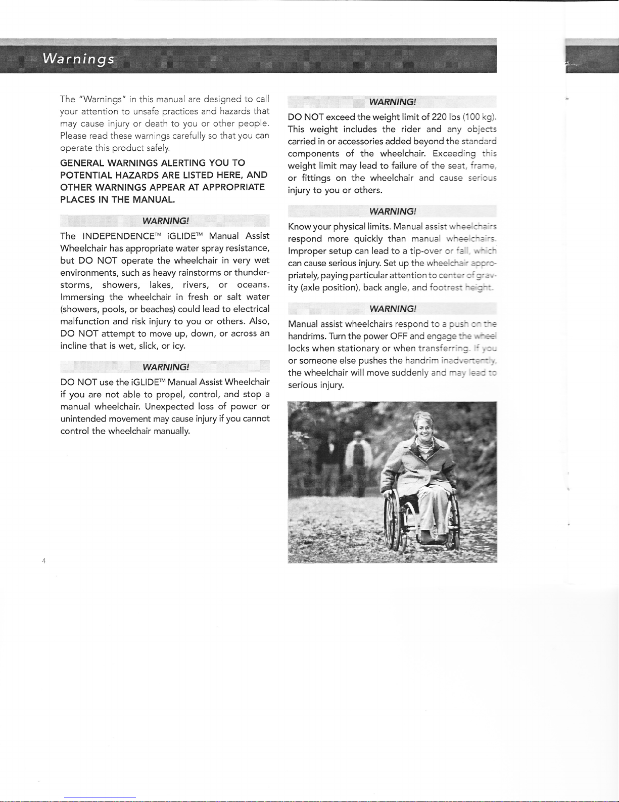
Know your physical limits. Manual assist rvheE :-=''s
respond more quickly than manual whee:-=''s.
lmproper setup can lead to a tip-over cr :a '.,- :-
can cause serious injury. Set up the wheeici.'e'' =-=.r.-
priately, paying particular attention to cet ?' =: ='=- , -
ity (axle position), back angle, and footre- -= 3-:-
WARN'NGI
Manual assist wheelchairs respond to a p;s- :- :-e
handrims. Turn the power OFF and engage:€ rr-€3
locks when stationary or when transfer:-^::" : _,:,
or someone else pushes the handrim inao'. e-:=- -.
the wheelchair will move suddenly and rr:, +a:::
serious injury.

The INDEPENDENCE-" iGLlDE"' Manual Assist
Wheelchair was designed to provide greatly
improved mobility for people who use manual or
powered wheelchairs. The iGLlDEr* Manual Assist
Wheelchair works like a manual wheelchair; pushing
on the handrims propels and controls the wheelchair.
There is no joystick. For the most part, the techniques
and skills for using a manual wheelchair will be the
same for the iGLIDETM Manual Assist Wheelchair.
Adjustments for balance, seating position, back
support, and most other options are like a manual
wheelchair. You must be able to manipulate a manual
wheelchair by means of the handrims in order to use
the INDEPENDENCETM iGLIDE'* Manual Assist
Wheelchair safely and effectively.
Before using your INDEPENDENCE-' iGLlDE"
Manual Assist Wheelchair, please read the entire
manual thoroughly, paying special attention to all
highlighted warnings. We suggest you keep the
manual handy for reference.
Here are some things you should consider as you
begin using your iGLIDE-" Manual Assist Wheelchair.
If you have been using a conventional
manual wheelchair...
The INDEPENDENCE-' iGLIDE-' Manual Assist
Wheelchair is different from a conventional manual
wheelchair in some important ways.
The iGLlDE " Manual Assist Wheelchair has electric
motors that help drive the rear wheels of the wheelchair
on a variety of different surfaces and terrains. You don't
have to make any adjustments; the motors will
automatically provide additional power to help you
negotiate slopes, carpet, grass, or gravel.
You will notice that pushing the iGLlDEr" Manual
Assist Wheelchair is easier than a conventional
manual wheelchair. As a result, the chair may seem
much more responsive than you are used to. We
recommend that you take time getting used to the
responsiveness of the wheelchair in a safe environment
and, ideally, with the help of a healthcare professional.
At about 56 pounds (with battery), the iGLIDE'"
Manual Assist Wheelchair does weigh somewhat
more than a conventional manual wheelchair. lf you
have been using a conventional manual wheelchair;
you or your assistant will have to adjust to the
additional weight when transporting the wheelchair.
lf you have been using a conventional
power wheelchair...
The INDEPENDENCETM iGLIDE'M Manual Assist
Wheelchair is different from conventional joystick-
controlled powered wheelchairs in the following
important ways.
Although it is powered, the iGLIDE'V Manual Assist
Wheelchair does not work like other power wheel-
chairs. The wheelchair must be moved, steered, and
braked by means of the handrlms. lf you do not push
on the handrim, the manual assist system will not
engage. Therefore, you must be able to exert some
force on the handrim in order to use the iGLIDE'M
Manual Assist Wheelchair.
Because the iGLIDE-^' Manual Assist Wheelchair
needs to be pushed like a manual wheelchail you
should work up gradually to the increased muscular
and cardiovascular activity associated with using the
iGLlDE" Manual Assist Wheelchair. Consult with
your healthcare professional, especially if it has been
some time since you used a manual wheelchair.

The iGLIDETM Manual Assist Wheelchair battery is a
Nickel Metal Hydride (NiMH) battery that is much
smaller and lighter than typical power chair batteries.
It is designed to last a typical full day on a single
charge, although this may vary based on weight and
surfaces traveled.
If you have been using a
power assist wheelchair...
You will notice that the INDEPENDENCE" iGLlDEry
Manual Assist Wheelchair technology is integrated
into the design of the wheelchair. You do not have to
remove the motors along with the wheels on the
wheelchair. See page 19 for directions on how to
remove the quick-release wheels.
The iGLIDE-' Manual Assist Wheelchair has
DeltaSenset' Technology, a patented system of
microprocessors and sensors that measures a user's
input and the resistance from the terrain. and auto-
matically adjusts the power for a consistent ride with
less manual effort. You will not have to change
power settings. You will notice that the wheelchair will
continue to "coast" even going up a grade or onto
a carpeted surface and that the wheelchair will siow
automatically going downhill.
Refer to Figure '1 for a full view of the iGLIDE-''
Manual Assist Wheelchair and many of :ne cars
described in the manual.
I
Wheel Lock
Figure 1: iGtlDE-" Manual Assist Wheelchair
Seat Mount Brackets
Handrim
Drive Assembly
Battery
Q.uick-Release Button
Backrest \
Power Button
\
Footrest \ ,
Caster Wheels
and Assembry\
WARN'NGI
Using an unfamiliar wheelchair without sufficient
training may lead to injury! To determine and establish
your particular safety limits, practice bending,
reaching, and transferring activities in several
combinations in a supervised environment BEFORE
attempting active use of the wheelchair.
1. General Operation Guidelines
1.1. Like any wheelchair, the following actions
while using the INDEPENDENCEf iGLIDET
Manual Assist Wheelchair could cause
instability and result in tipping of the
wheelchair:
. moving forward in the seat
. leaning over the top of the back upholstery
r shifting weight in the chair
. tilting the chair without assistance
. attempting curbs or obstacles
.. climbing or descending siopes greater
tl^an 6 degrees
1.2. Ltke any wheelchair, the following alterations
could resuit in increased instability of the
wheelchair:
. center of gravity adjustment
r position of the footrests
. tautness of the back upholstery
. rear seat height
. back angle adjustment
WARN'NG!
BEFORE attempting to transfer into or out of the
product. power the system OFf, and then every
precaution should be taken to reduce the distance
between the wheelchair and the surface you are
transferring onto. Also. be certain the wheel locks
are engaged to prevent the wheels from moving.
tYARNTNG!
When transferring into or out of the product. avoid
placing your hands on the seat mount brackets
located on both sides of the seat pan.
WARNTNGI
Use EXTREME caution when using a new seating
position for the first time.
WARNINGI
DO NOT use an escalator to move a wheelchair
between floors.
WARN'NG!
DO NOT operate on roads, streets, or highways
except when absolutely necessary to cross them,
and then do so only in a well-lit, controlled area
and with extreme caution.
WARNING!
It is possible for bolts and screws to work loose over
time. Retighten all bolts and screws monthly. Failure
to do so could result in personal injury or damage to
your wheelchair.
WARN'NG!
DO NOT attempt to move up or down an incline
with a water, ice, or oil film.
WARNING!
DO NOT use parts, accessories. or adapters other
than those authorized by Independence Technology.
WARN'NG!
DO NOT attempt to lift the product by any removable
(detachable) parts.
WARNING!
DO NOT stand on the frame of the wheelchair.
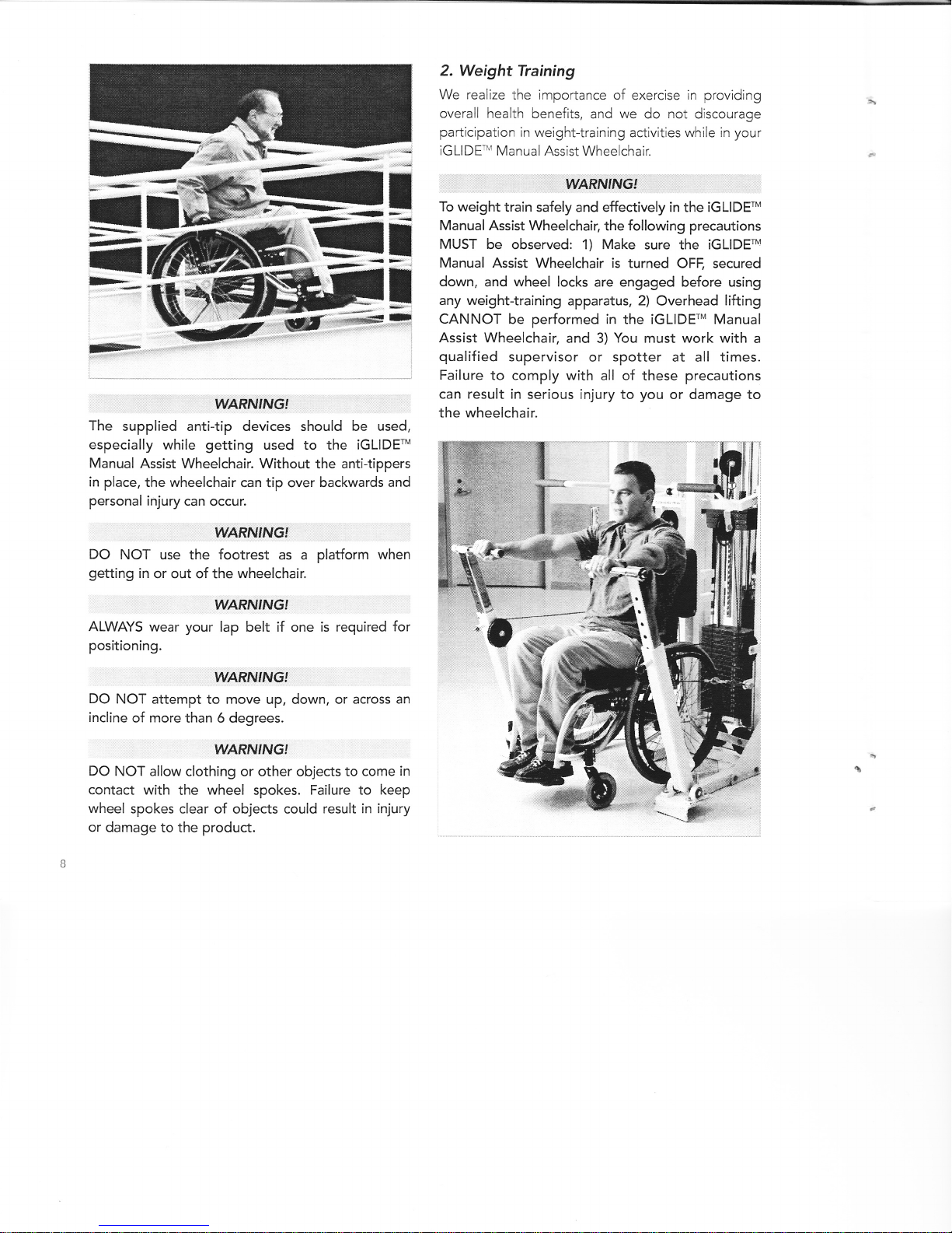
2. Weight Training
We realize the importance of exercise in providing
overall health benefits, and we do not discourage
participation in weight-training activities while in your
iG LIDE* Manual Assist Wl^eelchair.
il
.{f.l:.
il
aI
il
n
rryl|t!:,
WARNIN6!
The supplied anti-tip devices should be used,
especially while getting used to the iGLIDE'"
Manual Assist Wheelchair. Without the anti-tippers
in place, the wheelchair can tip over backwards and
personal injury can occur.
WARNING'
DO NOT use the footrest as a platform when
getting in or out of the wheelchair.
WARNING!
ALWAYS wear your lap belt if one is required for
positioning.
WARN'NGI
DO NOT attempt to move up, down, or across an
incline of more than 6 degrees.
tVARNTNG!
DO NOT allow clothing or other objects to come in
contact with the wheel spokes. Failure to keep
wheel spokes clear of objects could result in injury
or damage to the product.
WARf\IT'VG'
To weight train safely and effectively in the iGLIDETM
Manual Assist Wheelchair, the following precautions
MUST be observed: 1) Make sure the iGLlDEw
Manual ,Assist Wheelchair is turned OFF. secured
down, and wheel locks are engaged before using
any weight-training apparatus, 2) Overhead lifting
CANNOT be performed in the iGLIDE'" Manual
Assist Wheelchair, and 3) You must work with a
qualif ied supervisor or spotter at all times.
Failure to comply with all of these precautions
can result in serious injury to you or damage to
the wheelchair.
5r*'
b,.4
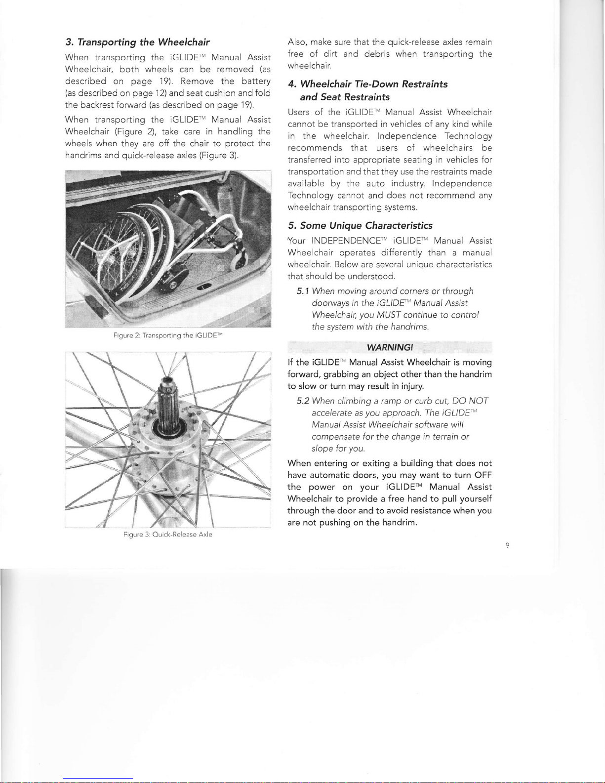
3. Transpotting the Wheelchair
When transporting the iGLIDE'M Manual Assist
Wheelchair, both wheels can be removed (as
described on page 19). Remove the battery
(as described on page '1 2) and seat cushion and fold
the backrest forward (as described on page 19).
When transporting the iGLIDE-' Manual Assist
Wheelchair (Figure 2), take care in handling the
wheels when they are off the chair to protect the
handrims and quick-release axles (Figure 3).
Also, make sure that the quick-release axles remain
free of dirt and debris when transporting the
wheelchair.
4. Wheelchair Tie-Down Restralnts
and Seat Restraints
Users of the iGLlDE" Manual Assist Wheelchair
cannot be transported in vehicles of any kind while
in the wheelchair. lndependence Technology
recommends that users of wheelchairs be
transferred into appropriate seating in vehicles for
transportation and that they use the restraints made
available by the auto industry. lndependence
Technology cannot and does not recommend any
wheelchair transportin g systems.
5. Some Unique Characteristics
Your INDEPENDENCE" iGLIDE;' Manual Assist
Wheelchair operates differently than a manual
wheelchair. Below are several unique characteristics
that should be understood.
5.1 When moving around corners or through
doorways in the |GLIDF', Manual Assist
Wheelchatr, you MUST continue to control
the system with the handrims.
WARN'NG!
lf the iGLIDE '' Manual Assist Wheelchair is moving
forward, grabbing an object other than the handrim
to slow or turn may result in injury.
5.2 When climbing a ramp or curb cut, DO NOT
accelerate as you approach. The iGLIDE"'
Manual Assist Whee/chair software will
compensate for the change in terrain or
slope for you.
When entering or exiting a building that does not
have automatic doors, you may want to turn OFF
the power on your iGLIDE'M Manual Assist
Wheelchair to provide a free hand to pull yourself
through the door and to avoid resistance when you
are not pushing on the handrim.
'm Figure 2: Transporting the iGLIDE'"
Figure 3: Quick-Release Axle
El ectromagn etic I nterfe re n ce (EMI)
from Radio Wave Sources
The INDEPENDENCE" iGLIDE'* Manual Assist
Wheelchair may be susceptible to electromagnetic
interference (EMl), which is interfering electromagnetic
(EM) energy emitted from sources such as radio
stations, W stations, amateur radio (HAM) transmitters,
two-way radios, and cellular phones. The interference
(from radio wave sources) can cause a manual assist
wheelchair to move by itself or to move in unintended
direclions. It can also permanently damage a manual
assist wheelchair's control system.
The intensity of the EMI can be measured in volts per
meter (V/m). A manual assist wheelchair can resist EMI
up to a certain intensity called the "immunity level";
the higher the immunity level, the greater the
protection. At this time, current technology is capable
of achieving at least a 20Y/m immunity level, which
provides useful protection from the more common
sources of radiated EMl. The immunity level of this
model of the INDEPENDENCE" iGLIDE'" Manual
Assist Wheelchair, as shipped with no further
modification, is 20 V/m.
There are a number of sources of relatively intense
electromagnetic fields in the everyday environment.
Some of these sources are obvious and easy to avoid.
Others are not apparent, and exposure is unavoidable.
However, we believe that by following the warnings
listed below, your risk from EMI will be minimized.
The sources of radiated EMI can broadly be classified
into these three types:
1) Handheld portable transceivers (transmitters-
receivers) with the antenna mounted directly on
the transmitting unit. Examples include: citizens
band (CB) radios; walkie-talkies; security, fire, and
police transceivers; cellular telephones; and
other personal communication devices. NOTE:
Some cellular telephones and similar devices
transmit signals while they are ON. even when not
being used.
2) Medium-range mobile transceivers, such as those
used in police cars, fire trucks, ambulances, and
taxis.'These usually have the antenna mounted on
the outside of the vehicle.
3) Long-range transmitters and transceivers, such
as commercial broadcast transmitters (radio
and W broadcast antenna towers) and amateur
(HAM)radios.
NOTE: Other types of handheld devices such as
cordless phones, laptop computers, AM/FM radios,
TV sets, CD players, and cassette players, and small
appliances, such as electric shavers and hair dryers, so
far as we know, are not likely to cause EMI problems
to your iGLIDE'M Manual Assist Wheelchair.
Manual Assist Wheelchair Electromagnetic
lnterference (EMI)
Because EM energy rapidly becomes more lntense
as one moves closer to the transmitting antenna
(source), the EM fields from handheld radio wave
sources (transceivers) are of special concern. lt is
possible to unintentionally brlng high levels of EM
energy very close to the powered wheelchair! control
system while using these devices. This can affect
manual assist wheelchair movement. There{ore, the
warnings listed below are recommended to prevent
possible interference with the control system of the
manual assist wheelchair.
10

tVARNTNG!
Electromagnetic interference (EMl) from sources
such as radio and TV stations. amateur radio (HAM)
transmitters, two-way radios, and cellular phones
can affect the iGLlDEtr Manual Assist Wheelchair.
Following the warnings listed below should reduce
the chance of unintended product movement, which
could result in serious injury.
1) DO NOT operate handheld transceivers
(transmitters-receivers), such as citizens band
(CB) radios, or turn ON personal communication
devices, such as cellular phones, while the
iGLlDEil Manual Assist Wheelchair is turned ON;
2) Be aware of nearby transmitters such as radio or W
stations, and try to avoid coming close to them;
3) lf unintended movement occurs, turn the manual
assist wheelchair OFF as soon as it is safe;
4) Be aware that adding accessories or components,
or modifying the manual assist wheelchair, may
make it more susceptible to EMI (NOTE: There is
no easy way to evaluate their effect on the overall
immunity of the manual assist wheelchair); and
5) Report all incidents of unintended movement to
the Technical Support Center and note whether
there was a source of EMI nearby at the time of
unintended movement.
1. ON/OFF Button
The ON/OFF button is located under the seat to the
left side of the seat rail (see Figure 4). The chair can
be used with or without the manual assist function.
The INDEPENDENCE-' iGLIDE-' Manual Assist
Wheelchair is designed to reset its computer
program each time the power is turned ON. Wait
at least 7 seconds after turning ON the power before
pushing the handrims. Also, DO NOT switch the
power ON or OFF while the wheelchair is in motion
or while pushing on the handrims. Otherwise, the
chair will shut down and you must recycle power
(turn it OFF, count to 3, then turn it ON again).
To conserve battery power, turn OFF the wheelchair
when not in use. lf the chair is left ON and not used
for more than 3 minutes, it will turn OFF automatically.
To turn the chair back ON, recycle the power (turn it
OFF, count to 3, then turn it ON again).
2. Using the iGLIDE* Manual Assist
Wheelchair
Please take the time to get familiar with your
iGLIDE'M Manual Assist Wheelchair in a safe and
supervised environment, with an assistant or an
experienced healthcare professional.
The INDEPENDENCE'" iGLIDE'" Manual Assist
Wheelchair can be used in a forward or reverse
direction, and can be steered just like a conventional
manual wheelchair.
.Howevel you must be alert to the following
characteristics of the manual assist system:
. At first, the wheelchair will seem much more
responsive than a conventional manual wheelchair.
This is a common experience, and you will adjust
to it with normal use. You may want to make
adjustments to the setup of your wheelchair to
take advantage of the manual assist function.
. lf you push on the tire to move the wheelchair,
it will resist. This is because the computer that
controls the motor tells the wheelchair to stay
stationary if it does not detect a push on the handrim.
o Turn OFF the iGLlDErv Manual Assist Wheelchair
when pushing from behind, because with the power
ON it will resist moving
without pushing on
the handrims.
. Always turn OFF the
wheelchair and apply
the wheel locks to
both wheels before
getting into or out of
the iGLIDE-'' Manual
Assist Wheelchair.
Figure 4: ON/OFF Button
. I#,ARMNGJ:. .
Grabbing the handrim while transferring into or out
of the product with the power ON can cause the
wheelchair to move rapidly and may lead to a fall.
When driving down a slope wlth the power ON,
the INDEPENDENCET' iGLIDE'M Manual Assist
Wheelchair will brake automatically. lf you need to
stop completely, use the handrim as normal (this will
require much less force than normal to effect a full stop).
lf you wish to descend faster, push the handrims to
drive the wheelchair as if on level ground.
WARN'NGI
DO NOT shut OFF power while on an incline, as the
wheelchair will not stop or slow itself going downhill
when turned OFF.
WARNING!
lf on an incline and holding onto the handrim for more
than 30 seconds. thereby providing resistance, the
system has a built-in safety feature that will shut OFF
and revert to manual mode, which may lead to unex-
pected downhill movement and a potential fall. lf in
manual assist mode, DO NOT hold the handrim for
more than 30 seconds unless you are able and pre-
pared to use your own strength to slow yourself
down.
WARIVING!
The wheelchair is designed to shut OFF power when
the battery level is too low or when the wheelchair
has not been moving for 3 minutes. lf you will be idle
for up to 3 minutes, turn the power OFF and revert
to manual mode. A low battery or idle condition may
cause the wheelchair to lose braking assist on a slope.
Without power, braking must be accomplished solely
by physical force on the handrims. Please check, or
have your assistant check, that the battery has
sufficient charge before attempting a slope greater
than you can manage without manual assist. Refer to
page 14 on checking the battery charge level.
. : wAFVllvGl
The battery tends to lose power more quickly
when traveling on terrain such as carpet or grass.
Regularly check your battery charge level (or have
your assistant check) to ensure that the battery has
sufficient charge before traveling on varied
terrains. Refer to page 14 on checking the battery
charge level.
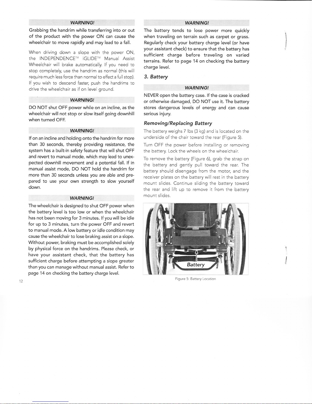
3. Battery
WARNING'
NEVER open the battery case. lf the case is cracked
or otherwise damaged. DO NOT use it. The battery
stores dangerous levels of energy and can cause
serious injury.
Removing/Replacing Battery
The battery weighs 7 lbs (3 kg) and is located on the
underside of the chair toward the rear (Figure 5).
Turn OFF the power before installing or removing
the battery. Lock the wheels on the wheelchair.
To remove the battery (Figure 6), grab the strap on
the battery and gently pull toward the rear. The
battery should disengage from the motor, and the
receiver plates on the battery will rest in the battery
mount slides. Continue sliding the battery toward
the rear and lift up to remove jt from the battery
mount slides.
1
I
I
I
Figure 5: Battery Location
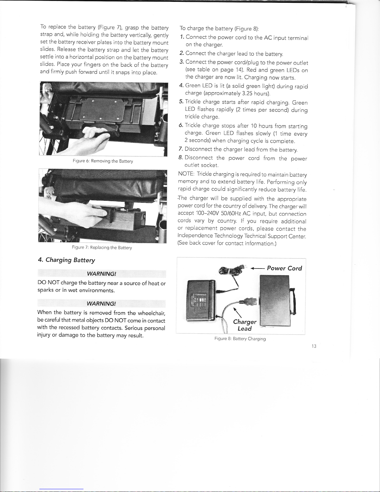
To replace the battery (Figure 7), grasp the battery
strap and, while holding the battery vertically, gently
set the battery receiver plates into the battery mount
slides. Release the battery strap and let the battery
settle into a horizontal position on the battery mount
slides. Place your fingers on the back of the battery
and firmly push forward until it snaps into place.
Figure 7: Replacinq the Battery
4. Charging Battery
WARNINGI
DO NOT charge the battery near a source of heat or
sparks or in wet environments.
WARNINGI
When the battery is removed from the wheelchair,
be careful that metal objects DO NOT come in contact
with the recessed battery contacts. Serious personal
injury or damage to the battery may result.
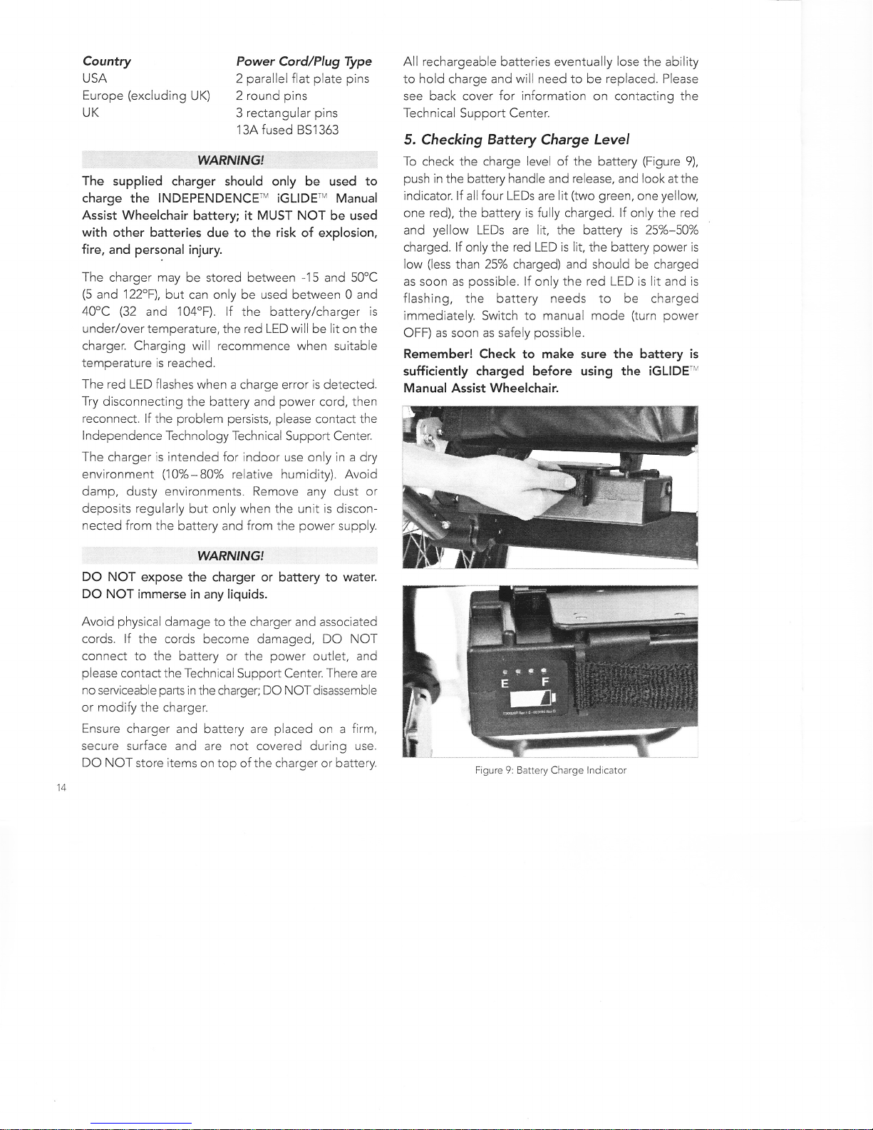
To charge the battery (Figure 8):
1. Connect the power cord to the AC input terminal
on the charger.
2. Connect the charger lead to the battery.
3. Connect the power cord/plug to the power outlet
(see table on page 14). Red and green LEDs on
the charger are now lit. Charging now starts.
4. Green LED is lit (a solid green light) during rapid
charge (approximately 3.25 hours).
5. Trickle charge starts after rapid charging. Green
LED flashes rapidly (2 times per second) during
trickle charge.
6. Trickle charge stops after 10 hours from starting
charge. Green LED flashes slowly (1 time every
2 seconds) when charging cycle is complete.
7. Disconnect the charger lead from the battery.
8. Disconnect the power cord from the power
outlet socket.
NOTE: Trickle charging is required to maintain battery
memory and to extend battery life. performing only
rapid charge could significantly reduce battery life.
.The charger will be supplied with the appropriate
power cord for the country of delivery. The charger will
accept 100-240V 50/60H2 AC input, but connection
cords vary by country. lf you require additional
or replacement power cords, please contact the
Independence Tech nolo gy Techn ical Support Center.
(See back cover for contact information.)
+ Power Cord
Figure 8: Battery Charging
Figure 6: Removing the Battery
Country Power Cord/Plug Type
USA 2 parallel flat plate pins
Europe (excluding UK) 2 round pins
UK 3 rectangular pins
134 fused 8S1363
:. '' = waRruflvct '
The supplied charger should only be used to
charge the INDEPENDENCEru iGLlDE" Manual
Assist Wheelchair battery; it MUST NOT be used
with other batteries due to the risk of explosion,
fire, and personal injury.
The charger may be stored between -15 and 5O'C
(5 and 122"F), but can only be used between 0 and
40"C (32 and 'l 04"F). lf the battery/charger is
under/over temperature, the red LED will be lit on the
charger. Charging will recommence when suitable
temperature is reached.
The red LED flashes when a charge error is detected.
Try disconnecting the battery and power cord, then
reconnect. lf the problem persists, please contact the
I ndependence Tech nolo gy Tech n ica I Su ppo rt Ce nter.
The charger is intended for indoor use only in a dry
environment (10%-80% relative humidity). Avoid
damp, dusty environments. Remove any dust or
deposits regularly but only when the unit is discon-
nected from the battery and from the power supply.
YYARNING!
DO NOT expose the charger or battery to water.
DO NOT immerse in any liquids.
Avoid physical damage to the charger and associated
cords. lf the cords beccme damaged, DO NOT
connect to the battery or the power outlet, and
please contact the Technical Support Center. There are
no serviceable parts in the charger; DO NOTdisassemble
or modify the charger.
Ensure charger and battery are placed on a firm,
secure surface and are not covered during use.
DO NOT store items on top of the charger or battery.
All rechargeable batteries eventually lose the ability
to hold charge and will need to be replaced. Please
see back cover for information on contacting the
Technical Support Center.
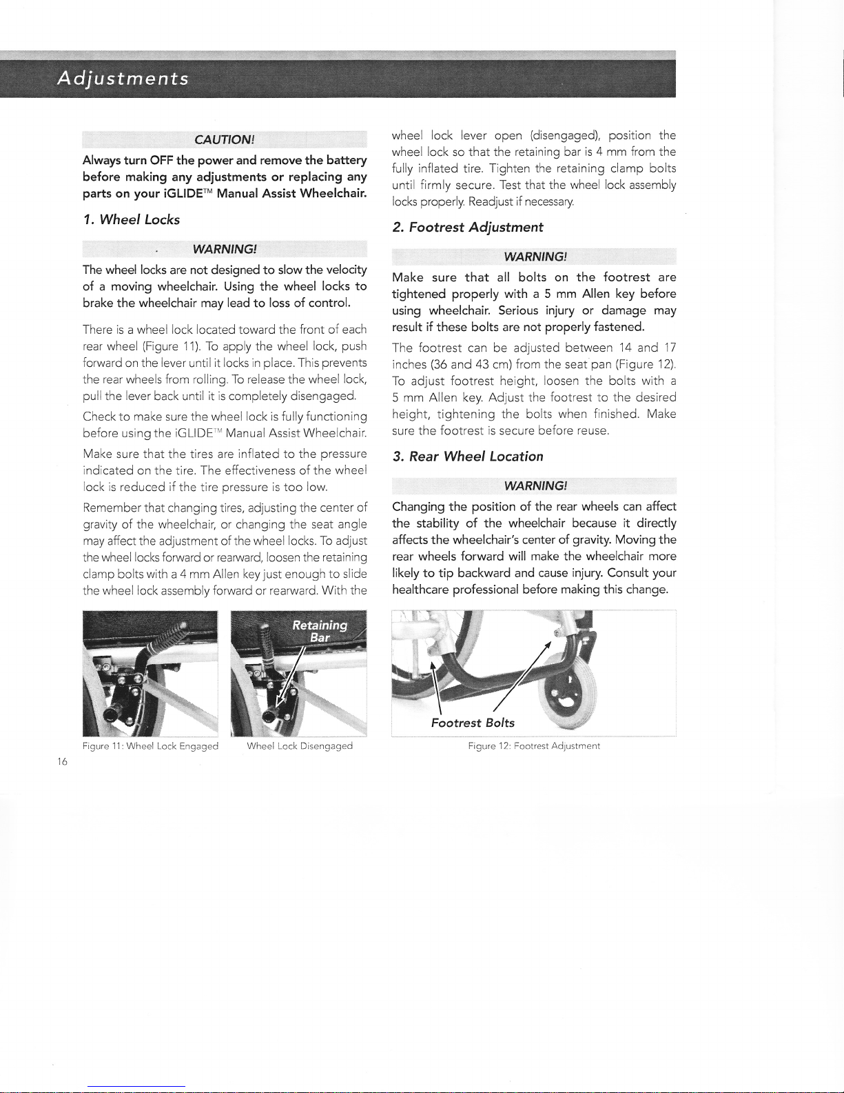
5. Checking Battery Charge Level
To check the charge level of the battery (Figure 9),
push in the battery handle and release, and look atthe
indicator. lf all four LEDs are lit (two green, one yellow,
one red), the battery is fully charged. lf only the red
and yellow LEDs are lit, the battery is 25%-50%
charged. lf only the red LED is lit, the battery power is
low (less than 25% charged) and should be charged
as soon as possible. lf only the red LED is lit and is
flashing, the battery needs to be charged
immediately. Switch to manual mode (turn power
OFF) as soon as safely possible.
Remember! Check to make sure the battery is
sufficiently charged before using the iGLIDE-'
Manual Assist Wheelchair.
Figure 9: Battery Charge Indicator

6. Replacing Fuse on Battery Case
The fuse on the battery case protects the battery
from malfunctioning (Figure '10). ln normal operation
of the iGLIDE'" Manual Assist Wheelchaic the fuse
should not blow. However, in case of a battery or
wire short, the fuse will need to be replaced. To
replace the fuse on the battery case, first remove the
battery from the wheelchair as described previously.
With the case on a firm surface, place a screwdriver
in the slot on the fuse holder, push in and turn
counterclockwise '1l4 of a turn. The fuse will pop out
of the case. Remove the fuse from the fuse holder by
pulling gently. Replace the fuse with a 20A/32Y
fast-blow fuse that is available through the Technical
Support Center (see back cover for contact information).
Push the new fuse in the fuse holder and place it
back into the battery case. Use a screwdriver to push
the fuse holder into the hole and turn 1/4 of aturn
clockwise until the fuse is back in place.
7. Storing Battery
DO NOT store battery in direct sunlight or in
eitreme humidity or heat. Be particularly careful
'about leaving a battery in a car or van on extremely
hot or cold days. lf the battery is to be stored for a
substantial period, arrangements should be made
to charge the battery at least every month.
8. Battery Disposal
Please use proper disposal methods for a NiMH
battery.
Fuse
Fuse Holder 4
Figure 1O: Removing/Replacing Battery Fuse
t
fl
t
j
q
,:: CAUTION! ,,,. ,,
Always turn OFF the power and remove the battery
before making any adjustments or replacing any
parts on your iGLIDE'M Manual Assist Wheelchair.
1. Wheel Locks
. WARN'NG'
The wheel locks are not designed to slow the velocity
of a moving wheelchair. Using the wheel locks to
brake the wheelchair may lead to loss of control.
There is a wheel lock located toward the front of each
rear wheel (Figure i1). To apply the wheel lock, push
forward on the lever until it locks in place. This prevents
the rear wheels from rolling. To release the wheel lock,
pull the lever back until it is completely disengaged.
Check to make sure the wheel lock is fully functioning
before using the iGLIDE-M Manual Assist Wheelchair.
Make sure that the tires are inflated to the pressure
indicated on the tire. The effectiveness of the wheel
lock is reduced if the tire pressure is too low.
Remember that changing tires, adjusting the center of
gravity of the wheelchair, or changing the seat angle
may affect the adjustment of the wheel locks. To adjust
the wheel locks forward or rearward, loosen the retaining
clamp bolts with a 4 mm Allen key just enough to slide
the wheel lock assembly forward or rearward. With the
wheel lock lever open (disengaged), position the
wheel lock so that the retaining bar is 4 mm from the
fully lnflated tire. Tighten the retaining clamp bolts
until firmly secure. Test that the wheel lock assembly
locks properly. Readjust if necessary.
2. Footrest Adjustment
WARN'NGI
Make sure that all bolts on the footrest are
tightened properly with a 5 mm Allen key before
using wheelchair. Serious injury or damage may
result if these bolts are not properly fastened.
The footrest can be adjusted between 14 and 17
inches (36 and 43 cm) from the seat pan (Figure'1 2).
To adjust footrest height, loosen the bolts with a
5 mm Allen key. Adjust the footrest to the desired
height, tightening the bolts when finished. Make
sure the footrest is secure before reuse.
3. Rear Wheel Location
}YARNINGI
Changing the position of the rear wheels can affect
the stability of the wheelchair because it directly
affects the wheelchair's center of gravity. Moving the
rear wheels forward will make the wheelchair more
likely to tip backward and cause injury. Consult your
healthcare professional before making this change.
Figure 12: Footrest Adjustment
ligi
Figure 11:Wheel Lock Engaged Wheel Lock Disengaged

WARNINGI
Make sure that all bolts on motor mount are
tightened properly with a 5 mm Allen key before
using wheelchair. Serious injury or damage may
result if these bolts come loose during use.
To change the rear wheel location (Figure 13),
turn power OFF and remove the battery. lnvert the
wheelchair and remove wheels as described on
page 19. Loosen the three bolts (5 mm Allen key) on
the motor mount on each side of the chair. Loosen
the bolts just enough to slide the motors either fore
oraft to desired position. Tighten the three bolts on
each side. Reinstall wheels.
DO NOT attempt to move the motors past the limits
indicated on the frame rails and ensure that the
motor mount positioning is the same on both sides
of the wheelchair, as measured from the limits.
WARNJNGJ .
Leave crossbar fasteners in position when changing
the location of the rear wheels (Figure 14).
Removing the crossbar could result in misalignment
or damage to the wheelchair.
4. Front Caster Location
WARNINGI
Make sure that all bolts on caster mount are
tightened properly with 5 mm and 3 mm Allen keys
before using wheelchair. Serious injury may result if
these bolts come loose during use.
For best performance, the front caster housing
should be perpendicular to the ground. The position
of the caster housing may be affected by changes in
the rear tire size, caster wheels, or other settings.
To adjust the front caster orientation (Figure '1 5). turn
the power OFF and place the wheelchair on a flat
surface and engage the wheel locks. Loosen the five
mounting bolts (5 mm Allen key) that attach the
housing to the frame, about one-half a turn. Loosen
the stop bolt (3 mm Allen key) at the bottom of the
caster mount, about one-half to one turn. lf you want
to move the caster housing forward, turn the top stop
bolt clockwise (3 mm Allen key) until the desired posi-
tion is reached. To move the housing backward, turn
the top stop bolt counter-clockwise. The housing
should be perpendicular to the ground, or use a level
ifyou have one.
Figure 13: Rear Wheel Position Adjustment
Figure 14: Crossbar Fasteners Figure 15: Caster Adjustment
Once at the desired position, retighten the mounting
bolts. Check that the alignment has not changed;
tighten the stop bolts.
5. Back Angle
t'VARNINGI
Make sure that all bolts on backrest are tightened
properly before using wheelchair. Serious injury may
result if these bolts come loose during use.
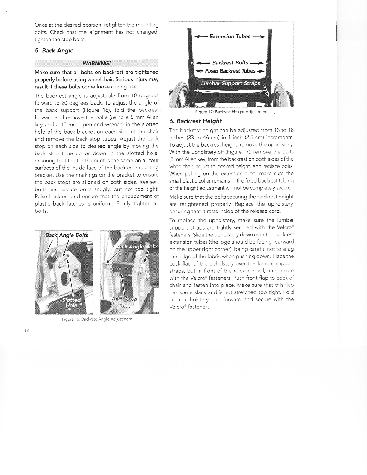
The backrest angle is adjustable from 10 degrees
forward to 20 degrees back. To adjust the angle of
the back support (Figure 16), fold the backrest
forward and remove the bolts (using a 5 mm Allen
key and a 10 mm open-end wrench) in the slotted
hole of the back bracket on each side of the chair
and remove the back stop tubes. Adjust the back
stop on each side to desired angle by moving the
back stop tube up or down in the slotted hole,
ensuring that the tooth count is the same on all four
surfaces of the inside face of the backrest mounting
bracket. Use the markings on the bracket to ensure
the back stops are aligned on both sides. Reinsert
bolts and secure bolts snugly, but not too tight.
Raise backrest and ensure that the engagement of
plastic back latches is uniform. Firmly tighten all
bolts.
Fiqure 16: Backrest Angle Adjustment
6. Backrest Height
The backrest height can be adjusted from 13 to 18
inches (33 to 46 cm) in 'l -inch (2.5-cm) increments.
To adjust the backrest height, remove the upholstery.
With the upholstery off (Figure 17), remove the bolts
(3 mm Allen key) from the backrest on both sides of the
wheelchair; adjust to desired height, and replace bolts.
When pulling on the extension tube, make sure the
small plastic collar remains in the fixed backrest tubing
or the height adjustment will not be completely secure.
Make sure that the bolts securing the backrest height
are retightened properly. Replace the upholstery,
ensuring that it rests inside of the release cord.
To replace the upholstery, make sure the lumbar
support straps are tightly secured with the Velcrou
fasteners. Slide the upholstery down over the backrest
extension tubes (the logo should be facing rearward
on the upper right corner), being careful not to snag
the edge of the fabric when pushing down. Place the
back flap of the upholstery over the lumbar suppoft
straps, but in front of the release cord, and secure
with the Velcroo fasteners. Push front flap to back o{
chair and fasten into place. Make sure that this flap
has some slack and is not stretched too tight. Fold
back upholstery pad forward and secure with the
Velcro'u fasteners.
+ Backrest Bolts ->
+ Fixed Backrest Tubes >
Figure 17: Backrest Height Adjustment
-'w
t.
v
E ',
ffi

7. Q.uick-Release Wheels
WARN'NG'
The wheel can come off in use if the quick-release is
not fully engaged, which may cause injury.
The rear wheels are equipped with a quick-release
function to allow the removal of the wheel without
any tools. Notice that the handrim and wheel are
separate parts. To remove the rear wheels, make
sure the power is turned OFF. Press the quick-release
button at the center of the handrim spider and pull
the wheel and handrim firmly away from the
wheelchair (Figure'18).
To replace the wheel, first ensure that the wheel being
replaced is on the correct side (left=red, right=green).
The color-coded handrim arm must be centered
Ouick-Release Axle
Handrim
Quick-
Release
Button
Handrim
Arm
Figure 18: Ouick-Release Axle
between the wheel spokes containing the same
color-coded mark.
Align the quick-release axle with the opening in the
drive. (NOTE: The quick-release axle will not go in
more than half an inch unless the teeth are aligned.
Also, remember to keep the color-coded handrim arm
centered between the corresponding spokes.) Press
the quick-release button, ensuring that the handrim
arm is not touching the spokes, and push the wheel on
until the teeth of the quick-release axle fully engage in
the motor. You may have to rotate the handrim slightly
in order to line up parts of the quick-release axle with
the mating parts in the drive.
Release the quick-release button and check to make
sure that the wheel is firmly locked in place by ensuring
that the quick-release button has returned to its
original position AND by pulling firmly on the wheel.
WARNINGI
DO NOT make adjustments to the wheel assembly
and associated mechanisms. Such adjustments
should only be made by a qualified lndependence
Jechnology Technical Support Specialist.
m
Wheel
5pokes
Drive Opening
Figure 19: Folding Backrest Latch

8. Folding Backrest Latch
To foid the backrest when the iGLlDE " Manual Assist
Wheelchair is unoccupied, first remove your cushion.
Locate the release cord found low on the rear of the
backrest upholstery. Pull up on the release cord and
fold the backrest forward (Figure '19). To unfold the
backrest, grab the crossbar and lift the backrest until
it firmly locks into position. Test that the latch is
engaged by pressing the backrest slightly forward. lf it
resists, it is properly engaged.
9. Anti-Tipp.ers
WARN'NG!
The anti-tip devices should be used, especially while
getting used to the iGLIDETU Manual Assist
Wheelchair. Without the anti-tippers in place. the
wheelchair can tip over backwards and personal
injury can occur.
The anti-tippers may prevent the wheelchair from
tipping over backwards (Figure 20). When properly
installed, the wheels should be facing downward at
all times.
To install the anti-tippers, insert the open end into the
receiver at the rear of the wheelchair, depress both
release buttons, and align the retaining buttons until
they snap into their slots. To remove the anti-tip devices,
depress the release buttons, wvist slightly, and remove.
10. Lap Belts
Lap beits are offered as optional equipment on the
iGLIDE '' Manual Assist Wheelchair. Please refer to
the instructions accompanying your lap belt system
for proper installation and use.
WARNTNGT
Serious injury can occur in the event of a fall from a
wheelchair. lf you require a lap belt for positioning,
be sure to use it at all times.
DO NOT use the product without securing the lap belt
if your healthcare professional has determined that
it is required for safe operation of the wheelchair.
11. When to Use On-Call Service
Call the Technical Support Center anytime your
INDEPENDENCET' iGLlDE" Manual Assist
Wheelchair is not functioning properly. Please see
back cover for instructions on how to contact the
Technical Support Center.
12. Customer Repracernent Units
WARNING!
Use of unauthorized replacement parts or accessories
can compromise the ability of the product to
function safely. Personal injury could result. The
warranty will become null and void. Use only
replacement parts and accessories that are authorized
by lndependence Technology, L.L.C.
Customer replacement units are components you
are responsible for removing and replacing. An
authorized lndependence Technology Customer
Engineer will be sent to replace parts that are not
designated for customer repair (these parts are
called "field replacement units").
Order customer replacement units from the Technical
Support Center. Replacement parts are shipped with
instructions that describe how to remove the old part,
and install and test the replacement part. lf you have
difficulty replacing a part yourself, call the Technical
Support Center. You will be guided through the
replacement procedure. You will also receive
instructions on how to pack and ship damaged parts
back to Independence Technology.
lf a part is not functioning correctly, it should be
repaired or replaced. Contact the Technical Support
Center if you need assistance.
II
Table of contents


