Stand Aid 1600 User manual

INSTRUCTIONS AND WARRANTY FOR
STAND AID 1600
STAND AID SERIAL #___________
All Stand Aid models should be used only on level, smooth surfaces. Please
exercise caution and good judgement when operating your unit.
CAUTION:
PO BOX 386
Sheldon, IA 51201
(800) 831-8580
(712) 324-2153
Fax: (712) 324-5210
STAND AID 1600/
ECONOSTAND
MAKERS OF STAND AID, POWER
TOILET AID AND FREEDOM CHAIR
GETTING TO KNOW YOUR
STAND AID 1600
REPLACEMENT PARTS
READ complete manual
CAREFULLY BEFORE
attempting operation.
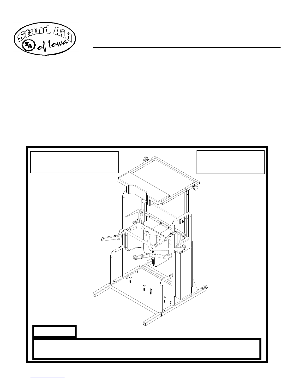
STANDARD MODEL (1600) SHOWN

INTRODUCTION
Thank you and congratulations on your purchase of the STAND AID
Model 1600. We are certain the benefits you receive from standing
with our STAND AID will enhance your health and outlook on life.
GENERAL INFORMATION
After unpacking your Stand Aid 1600, place any parts that are not
attached to the Stand Aid 1600 on the floor, using the parts list to get
familiar with the unit and parts. On the standard Stand Aid 1600 there
should be no tools needed to adjust the unit for your standing
pleasure. The standard unit with a wheel kit option will require a
couple of tools, 2 –open end 7/16” wrenches. The standard unit with
the Safety Gate option may require a 3/16” Allen wrench. Check
your packing list for the options that came with your unit.
Parts included in the standard unit, 1 –Sling to your specifica-
tion, 1 –Safety Belt, 2 –Heel straps, 1 –Toe Strap.
Parts included in the standard unit with Wheel Kit option,
includes all parts from the standard unit, and 4 –wheel brackets with
locking caster wheels, and bolts and nuts. Two of these wheel bracket
and locking caster wheels will need to be placed and bolted onto the
frame of the unit.
Parts included in the standard unit with Safety Gate option, in-
cludes all parts from the standard unit, and Safety Gate brackets,
Safety Gate arm, 1 –2” Safety Gate pad and 1– 4” Safety Gate pad.
This option will be placed onto the machine for your convenience.
Another option with the Safety Gate is the Back Support, which also
will be bolted onto the Safety Gate already, you will need to place the
Back Support “top” onto the Back Support “bottom”, and tighten the
knob to your desired height.
Page 2

TABLE OF CONTENTS
Cover .............................................................................Page #1
Introduction and General information..............................Page #2
Table of Contents and Stand Aid 1600 Models...............Page #3
Limited Warranty information..........................................Page #4
Safety Precautions ............................................................Page #5
Know your Stand Aid 1600 and Lift Operations .............Page #6
Lift Operations cont..........................................................Page #7
Parts Breakdown and Parts List .......................................Page #8
Assembly Instructions ......................................................Page #9
Assembly Instructions (cont.) ..........................................Page #10
Trouble Shooting, Warning on Ripping Table Pad ..........Page #11
Optional Safety Gate/Back Support .................................Page #12
Lateral Back Support Option............................................Page #13
Head Rest Option .............................................................Page #14
Wheel Kit Option .............................................................Page #15
Back Cover .......................................................................Page #16
WHEN CALLING FOR SERVICE PLEASE HAVE THE SERIAL NUMBER OF YOUR UNIT READY
FOR THE STAND AID REPRESENTATIVE THIS WILL HELP IN THE SERVICING OF YOUR
STAND AID 1600
MODELS
Model 1600 Standard unit
Options available with the 1600 standard unit include:
* The Safety Gate
* The Back Support
*The Lateral Back Support
* The Head Rest
* The Wheel Kit
Page 3

Each Stand Aid of Iowa, Inc. product has been carefully
inspected and tested before shipment.
Accordingly, we warrant each STAND AID 1600 which is
sold against defects in workmanship and material under nor-
mal use for life, excluding the hydraulic jack which is war-
ranted for one year from the date of shipment from Stand Aid.
This warranty shall not extend to and we shall have no re-
sponsibility with respect to products which have been abused,
misused, altered or as to which repair has been made or at-
tempted by others.
This warranty is made lieu of all other warranties with
respect to the product covered hereby and there are no other
warranties, whether expressed or implied of merchantability
or otherwise, except the warranty expressly stated herein. The
remedy set forth herein shall be the sole exclusive remedy of
any purchaser with respect to any defective product. Under
no circumstances shall STAND AID OF IOWA be liable for
any injury, loss, damage or expense suffered or incurred with
respect to any misuse of the STAND AID OF IOWA’S
products.
If you have any questions or need further information,
please feel free to call our offices at: 1-800-831-8580.
LIMITED WARRANTY
STAND AID 1600 SERIES
Page 4

SAFETY PRECAUTIONS
1. If at all possible have someone assist you with the first several
stands, to help with adjustment of the machine for your comfort
and for you to become familiar with the unit.
2. Always use on a level and smooth surface.
3. Do not operate the unit if it appears damaged, or is not operating
correctly. Consult our service department.
4. Never raise or lower the lift with hands on or by the lift arms or
lift arm linkage.
5. Keep all body parts away from moving parts on the unit at all
times.
6. Keep younger children away while operating this unit.
7. Do not use if the Jack is leaking, consult our service department.
8. Always make sure that the sling is positioned correctly under the
buttock and the D-Rings of the sling are on the lift hooks prop-
erly.
9. Never leave children unattended while in the standing position.
10. Do not release the jack without something for the person to sit on
when in the down position.
Page 5

ATTENTION: IMPORTANT
We ask that you take time to acquaint yourself with your Stand Aid 1600
and its adjustments. We highly recommend that someone assist you as you fa-
miliarize yourself with the unit. Again, we remind you to use your Stand Aid
1600 only on level surfaces.
OPERATING INSTRUCTIONS FOR STAND AID 1600
Push the jack release lever down while applying pressure downward on the
lift arms. Place the sling under your buttocks with the rings exposed on each
side. Next, position your wheelchair in the rear of the Stand Aid 1600. Loosen
the foot straps on the floor of the Stand Aid 1600 and place your feet on the floor.
The straps that fit over the top of your instep should be snug but not tight, see im-
age #1. The heel straps should fit behind the heel to prevent the foot from slip-
ping. Adjust the height of the knee pad by loosening the adjustment knobs on the
back side. Raise or lower the knee pad so your knees are centered in the pad see
Image #1 (Stand Aid 1600 not shown but strapping is the same)
Image #2
Page 6
HEEL STRAP TOE STRAP

Correct sling size is important for your comfort and safety. The sling “D-
rings” should slip easily onto the lift arm hooks see image #1 below. We
recommend that the lift arm slide hook adjustment should be approximately
midway between the hip and waist when you are in the standing position
see image #2. After a few standing sessions, you will find the most com-
fortable setting for your slide hooks.
To raise yourself to the stand position, simply pump the jack handle back and
forth. Carefully lift yourself until your legs are straight and you feel comfortable.
IMPORTANT: Exercise caution the first several times you raise yourself to as-
sure not only your safety, but also your comfort.
Once you are in an upright position, secure the safety belt and pad around your
upper back. Table height adjustment is important for upper body control. The
chest pad should be positioned near the bottom of the sternum, the point on your
rib cage where your bottom two ribs meet. In order to maintain correct posture,
the table may be adjusted in or out in order to align the upper and lower portion of
your body .
Now that most adjustments have been made, check and retighten all knobs to
ensure that your Stand Aid 1600 will remain in proper position. To lower yourself,
release the safety belt and safety gate, push downward on the jack release lever.
Page 7
Image #1 Image #2

1. 8200-2001 1 Stand Aid 1600 Frame
2. 8200-2003 1 Lift Bar
3. 8200-2000 2 Lift Bar Bushing
4. 8200-2004 4 Lift Linkage
*5. 8200-2040 1 Rt. Lift Arm
*6. 8200-2002 1 Lt. Lift Arm
7. 8200-2005 1 Rt. Lift Arm Hook
- 2600-3000 1 Rt. Lift Arm Hook Cover
- 2500-3006 2 Rubber Mocap
8. 8200-2006 1 Lt. Lift Arm Hook
- 2600-3001 1 Lt. Lift Arm Hook Cover
- 2500-3006 2 Rubber Mocap
9. 8200-2018 1 Stabilizer Bar
10. 2500-3000 8 Adjustment Knobs
11. 8200-2012 1 Knee Pad Mt.
12. 8200-2019 2 Knee Pad Slides
13. 2600-3002 1 Knee Pad
14. 8200-2020 2 Bottom Legs
15. 2500-3001 2 Front Wheels
16. 2500-3002 1 Hydraulic Jack
17. 8200-2009 1 Jack Lobe
18. 8200-2021 1 Jack Mount
19. 8200-2007 1 Jack Pump Linkage
20. 8200-2008 1 Pump Handle
- 2500-3003 1 Pump Handle Cover
21. 8200-2015 1 Release Lever
- 2500-3007 1 Release Lever Mocap
22. 8200-2014 1 Release Lever Linkage
23. 8200-2016 1 Side Cover
24. 8200-2050 2 Table Extensions
25. 8200-2048 1 Rt. Table Arm
26. 8200-2049 1 Lt. Table Arm
27. 8200-2010 1 Table Frame
28. 8200-2017 1 Table (plexi-glass)
29. 8200-2011 1 Chest Pad Bracket
STAND AID 1600 PARTS BREAKDOWN and PARTS LIST
REF. # PART # QTY. DESCRIPTION
1
2
3
4
5
6
7
8
10
9
11
12
13
14
15
16
17 18
19
20
21
22
23
24
24
25
26
27
28
29
30
31
32
10
10
10
33
REF. # PART # QTY. DESCRIPTION
30. 2600-3003 1 Chest Pad
31. 8200-2013 2 Table Clip
32. 2500-3004 1 Jack Spring
33. 2600-3004 1 Medium Shroud
34. 2600-3005 1 Sling (not shown)
35. 2600-3006 1 Safety Belt (not shown)
36. 2600-3007 2 Heel Straps (not shown)
37. 2600-3008 1 Toe Strap (not shown)
38. 2500-3005 1 Jack Clevis Pin
Note: Assembly Instructions and fasteners used are
on page 9 & 10.
38
Page 8
* Optional sized lift arms are available. Contact Stand
Aid to fit individual needs.

ASSEMBLY INSTRUCTIONS
16
18
IMAGE #2
IMAGE #1
2
3
4
5
6
9
7
38
NOTE: Refer To Main Diagram on Pg. #8 for vis-
ual unless otherwise specified.
1. Insert the two mainframe support legs (#14) into bottom
rear mainframe (#1) tubes. Secure using 5/16” x 1-1/2” Roll
Pin.
2. Attach the two wheels (#15) to the front of the mainframe
bottom tubes using 1/4” x 1-1/2” bolt w/ locknut
3. Insert the drive bar (#2) with the nylon bushings (#3) on
each end into mainframe. Secure in the u-mounts located in-
side the mainframe using 5/16“ x 2-1/2“ bolt w/ locknut. See
image #1 at right.
4. Attach the linkage plates (#4) to the block mounts on the
mainframe using 1/4” x 1-3/4” bolt w/ locknut.
5. Attach the right and left lift arms (#5 & #6) to the drive bar
arms. (drive bar arms go between the lift arm plates) Secure
using 5/16“ x 3/4“ roll pin. The bottom of the lift arms attach
at the bottom of the drive bar and in between the linkage
plates on each side with 1/4“ x 1-3/4“ bolt w/ locknut. Slide
the adjustable lift arm hooks (#7 & #8) onto the lift arms and
secure using the threaded knobs (#10). NOTE: Desired posi-
tion can be determined at any time.
6. Insert the stabiliser tube (#9) into the lift arm tubes on each
side. Secure with self-tapping screws through stabilizer tube
and lift arm tube.
7. Attach the jack mount bracket (#18) to the mainframe.
Bracket mounts at the lower right or left (depending on model
ordered) side of mainframe, inside of frame upright. See im-
age #2 at right. Secure using 3/8“ x
1-1/2“ bolt w/ locknut.
8. Mount the hydraulic jack (#16) to the jack mount bracket
using two 5/16“ x 1/2“ bolt w/ flatwasher. NOTE: Jack
mounts on with the pump linkage to the outside. See image
#2 at right.
9. Attach the jack clevis to the drive bar right outside arm us-
ing pin (#38) and cotter pin. see image #1 at right.
10. IMPORTANT: Assemble the knee pad mount (#11),
the two slide plates (#12), and the knee pad (#13) simultane-
ously. Place knee pad mount (#11) between the slide plates
(#12). Center this assembly and attach to the knee pad (#13)
using 10-24 x 3/4” machine screws, two flatwashers under the
slides (#12) to provide clearance for the knee pad mount
(#11) slides.
11. Attach the whole knee pad assembly to the mainframe
front cross tube. Secure using two 10-24 x 1/2“ machine
screws. NOTE: The channel on the knee pad mount fits over
the drive bar.
1
Page 9

19
21
17
22
ASSEMBLY INSTRUCTIONS (cont.)
12. Attach the jack pump handle (#20) to the handle bracket
on the mainframe. Secure using 3/8“ x 2-1/2“ bolt w/ lock-
nut.
13. Insert 3/8” x 2-1/2” bolt through the hole just behind
the pump handle bracket. Using two nuts leave 1-3/4” of the
bolt sticking out from the mainframe. This acts as a rest for
the pump handle.
14. Attach the jack release lever (#21) to the tab located
toward the top of the mainframes right upright using 1/4“ x
3/4“ bolt w/ flatwashers and locknut. See image #3 at right
15. Attach the pump handle linkage (#19) to the jack pump
linkage, and to the mounting ear on bottom of the pump han-
dle. Secure using 1/4“ locknut. See image #4 at right for
proper mounting direction.
16. Attach the jack lobe (#17) to the jack release valve.
Tighten the allen screws on the jack lobe. See image #4.
17. Attach the jack release linkage (#22) to the jack
lobe,and the release lever. See image #4.
At the hole just below and to the rear of jack repeat step 13
with spring (#32) on the bolt. Secure spring, and release lever
linkage with nut, secure to release lever with nut also. (refer
to main diagram on pg. 8 for proper direction)
18. Insert vertical adjust tube (#24) into the mainframe re-
ceiver tubes. Secure at desired height with threaded knobs.
(height can be adjusted at any time)
19. IMPORTANT: TABLE TOP ASSEMBLY
1. Insert table frame (#27) into right and left insert
slides (#25 & #26). Secure with two adjustment knobs.
2. Slide the table frame (#27) and the insert slides (#25 &
#26) into the table adjust vertical tubes (#24). Secure
using 10-24 x 1-1/4” machine screws with locknuts.
3. Secure chest pad bracket (#29) to the table frame
(#27) tubes using pop rivets.
4. Slide table glass (#28) into table frame and under table
frame tabs. Secure table glass (#28) to chest pad
bracket (#29) using two 10-24 x 3/4” machine screws
with locknuts.
4. Mount the chest pad (#30) to the chest pad bracket
(#29) using 10-24 x 1/2” machine screws.
5. Attach the table clips (#31) to the chest pad using 10-24
x 1/2” machine screws. On the other end secure to the
table frame tubes using pop rivets.
20. Attach side cover (#23) to the outside of mainframe
over jack assembly using self-tapping screws.
Page 10
IMAGE #4
IMAGE #3
NOTE: Refer To Main Diagram on Pg. #8 for vis-
ual unless otherwise specified.
20

Page 11
TROUBLE SHOOTING
PROBLEM SUGGESTION
Pumping pump handle but won’t lift
patient.
Pump arm very hard to pump.
Patient is in the standing position, but
slowly goes down.
Tried to tighten knobs for any of the
adjustments, won’t stay tight, or
knob won’t stay in.
Check that release lever isn’t held
down, lift lever up, try again. Check
Jack for leakage, jack is out of fluid.
Jack lobe needs to be re-adjusted.
Check lift linkage / lift arms, making
sure there is nothing stopping the
lifting motion. May need to release
pressure.
May be pumped to maximum exten-
sion
Readjust the Jack lobe. Lift up on
release handle. Replace jack.
Stripped threads, try to re-tap, if
that doesn’t work you may have to
tap the hole out to 3/8-16 and try
3/8” knob.
“Warning”
When pumping the jack handle back and forth please be sure the lift arms have enough
clearance to go under the table pad. By not doing so you may rip or tear the upholstery of
the table pad. (see below)

4
7
8
56
1
3
2
9
11
12
10
BACK SUPPORT
STAND AID 1600 (optional) SAFETY GATE
With BACK SUPPORT
Page 12
1. Attach the left and right extension tubes (#1 & #2) to the main
frame, secure the clamps to the mainframe tubes both sides.
2. Attach the safety gate lock (#3) to the left or right extension tube
by tightening the clamp. Height adjustment may be required later.
3. Attach the safety gate assembly (#4, #5 , & #6) to the Left or
Right Extension tube by tightening the gate mount (#6) clamps
around tube. Height adjustment may be required later.
4. Mount the back support mount (#7) to the safety gate using the
mounting strips (#8), and 1/4“ x 1-1/2“ bolts.
5. Assemble the back pad (#9) to the back pad mount (#11) with two
10-24 x 1/2“ bolts. Insert this assembly into the back support ver-
tical slide (#10), and secure with the adjusting knob (#12). Next
slide this assembly onto the back support mount (#7) and secure
with an adjustment knob (#12) to desired height.
Parts List
1. 8215-2057 1 Right Safety Gate Ext.
2. 8214-2028 1 Left Safety Gate Ext.
3. 8213-2025 1 Safety Gate Lock
4. 8210-2026 1 Safety Gate
- 2600-3009 1 Safety Gate Pad (not shown)
5. 8211-2023 1 Swivel Hinge
6. 8212-2024 1 Gate Mount
7. 8200-2036 1 Back Support Mount
8. 8200-2045 4 Back Support Mount Links
9. 2600-3010 1 Back Support Pad
10. 8221-2030 1 Back Support Vert. Slide
11. 8225-2034 1 Back Pad Mount
12. 2500-3000 4 Adjustment Knob
REF. # PART # QTY. DESCRIPTION Assembly Instructions
SAFETY GATE
The “SAFETY GATE” easily attaches right to the frame of the Stand Aid 1600
to give you added support. One four inch pad and one two inch pad will ac-
company the Safety Gate. It will depend on the physical build of the user as to
what pad will be used. These pads are placed on the Safety Gate for comfort
and security. A double hinge lock serves as the latch. This latch can be ordered
on either side of the Stand Aid 1600.
The “SAFETY GATE BACK SUPPORT” can also be added for those requiring
more back support. This attachment easily clamps onto the Safety Gate and
comes with an extra safety belt to hold the upper body snug against the back
rest for additional support.

Page 13
19
17
16
18
15
14
13
12
11
10
9
8
7
6
5
4
SAFETY GATE
3
2
1
1. Attach the left and right extension tubes (#1 & #2) to
the mainframe, secure the clamps to the mainframe
tubes both sides.
Assembly Instructions
1. 8215-2057 1 Right Safety Gate Ext.
2. 8214-2028 1 Left Safety Gate Ext.
3. 8213-2025 1 Safety Gate Lock
4. 8210-2026 1 Safety Gate
5. 8211-2023 1 Swivel Hinge
6. 8212-2024 1 Gate Mount
7. 8220-2029 1 Back Support Mount
8. 8200-2045 4 Back Support Mount Links
9. 8222-2031 1 Back Support Adjust
10. 8221-2030 1 Back Support Vert. Slide
11. 8225-2034 1 Back Pad Mount
12. 8270-2045 1 Rt. Pad Mount Adjuster
13. 8270-2046 1 Lt. Pad Mount Adjuster
14. 2600-3010 1 Back Support Pad
15. 8200-2038 1 Outside Pad Mount
16. 8200-2052 1 Flip-Up Pad Mount
17. 8200-2053 1 Flip-Up Pad Slide Adjust
18. 2600-3012 2 Lateral Wide Pad
19. 2500-3000 4 Adjustment Knob
20. 2500-3011 1 1/4” Lock Pin (not shown)
REF. # PART # QTY. DESCRIPTION
Parts List
STAND AID 1600 (optional) SAFETY GATE
LATERAL BACK SUPPORT
The “SAFETY GATE and LATERAL BACK SUPPORT” can also be added
for those requiring more back support. This attachment easily clamps onto the
Safety Gate and comes with an extra safety belt to hold the upper body snug
against the back rest for additional support. The standard back support is re-
placed with the back support below.
2. Attach the safety gate lock (#3) to the left or right extension tube
by tightening the clamp. Height adjustment may be required later.
3. Attach the safety gate assembly (#4, #5 , & #6) to the left or right
extension tube (#2) by tightening the gate mount (#6) clamps
around tube. Height adjustment may be required later.
4. Assemble the back support adjustment assembly (#7, #9, & #10) by
sliding The tubes together, #10 slides into #9, and slides over the
back support mount (#7) attach using lock pin (#20) . Secure the
adjusting knob (#19) at desired height. Attach this assembly to the
safety gate using the mounting strips (#8) and 1/4“ X 1-1/2“ bolts and
locknuts.
5. Assemble the back pad (#14) to the back pad mount (#11) with
10-24 x 1/2“ bolt. Insert this assembly into the back support
vertical slide (#10), and secure with the adjusting knob (#19).
6. Attach the lateral wide pad (#18) to the outside pad mount (#15)
and to the flip-up pad mount (#16) using 10-24 X 1/2” bolts.
7. Slide the outside pad mount (#15) into the pad mount adjuster (#12).
Secure the flip-up pad mount (#16) to the flip-up pad adjust slide (#17)
using a 1/4” X 1-1/2” bolt and locknut. Slide this assembly into the
other pad mount adjuster (#13). Slide both of these pad mount
assemblies onto the back support adjust (#9), and secure with the
adjusting knobs (#19). Be sure to install the flip-up pad assembly
(#16 & #17) on the same side as the safety gate swivel hinge (#5).
Width adjustment may be required later.
LATERAL BACK SUPPORT

Page 14
1. Attach the left and right extension tubes (#1 & #2) to the main
frame, secure the clamps to the mainframe tubes both sides.
2. Attach the safety gate lock (#3) to the left or right extension tube
by tightening the clamp. Height adjustment may be required later.
3. Attach the safety gate assembly (#4, #5 , & #6) to the left or right
extension tube (#2) by tightening the gate mount (#6) clamps
around tube. Height adjustment may be required later.
4. Assemble the head rest adjustment assembly (#7, #9, & #10) by
sliding the tubes together. Slide the head rest vertical slide (#10)
over the lower neck support slide (#9), slide the back support
mount (#7) into the lower neck support (#9) attach using lock pin
(#14) . Secure the adjusting knobs (#13) at the desired positions.
Attach this assembly to the safety gate using the mounting strips
(#8) and 1/4“ X 1-1/2“ bolts and locknuts.
5. Assemble the head rest pad (#12) to the head rest mount (#11) with
three 10-32 x 5/8“ socket head cap screws. Insert this assembly
into the head rest vertical slide (#10), and secure with the adjusting
knob (#13).
Assembly Instructions
12
Parts List
HEAD REST
1. 8215-2057 1 Right Safety Gate Ext.
2. 8214-2028 1 Left Safety Gate Ext.
3. 8213-2025 1 Safety Gate Lock
4. 8210-2026 1 Safety Gate
5. 8211-2023 1 Swivel Hinge
6. 8212-2024 1 Gate Mount
7. 8220-2029 1 Back Support Mount
8. 8200-2045 4 Back Support Mount Links
9. 8520-1002 1 Lower Neck Support Slide
10. 8520-1001 1 Head Rest Vert. Slide
11. 8520-1000 1 Head Rest Mount
12. 2600-3026 1 Head Rest Pad
13. 2500-3000 3 Adjustment Knob
14. 2500-3011 1 1/4” Lock Pin (not shown)
REF. # PART # QTY. DESCRIPTION
11
8
10
7
6
5
4
SAFETY GATE
2
11
3
9
13
STAND AID 1600 (optional) SAFETY GATE
HEAD REST
The “SAFETY GATE and HEAD REST” can also be added for those requiring
more head support. This attachment easily clamps onto the Safety Gate.

1
DETAIL VIEW A
SEE DETAIL
VIEW A
2
2
1
STAND AID 1600 (optional) WHEEL KIT
Stand Aid of Iowa, Manufacturer of electric lifts and mobile standing
frames, recently announced the addition of a new option that will allow the
economy frame to be easily moveable.
By adding four 5 inch swivel, locking caster wheels to the original model,
the Stand Aid 1600 can be safely used to provide mobility while the patient is in
the standing frame.
With this addition to the line, Stand Aid of Iowa now offers six different
models designed to provide the outstanding benefits of passive standing.
Call 1-800-831-8580 for more information or a free video tape.
Page 15
If you have added the 5” caster wheel kit, please note the operation of the brake system.
The front and rear wheels will swivel, but the brake system is located directly on the wheel
to keep the Stand Aid 1600 from rolling. To engage the lock on the caster wheel you must
press the lock down, depress the lock and the wheel will move freely. (see below)
PRESS DOWN
TO LOCK
1. 2500-3008 1 Caster Wheel
2. 8230-2035 1 Wheel Mount
REF. # PART # QTY. DESCRIPTION
ASSEMBLY INSTRUCTIONS
1. Insert wheel mounts (#2) into
the mainframe bottom tubes.
2. Secure the rear wheel mounts
with roll pin.
3. Secure the front wheel mounts
with a bolt and nut. Slide the
mount past the bolt hole and
install the bolt in front of the
wheel mount.(see detail view A)
4. Thread the caster wheels (#1)
into the wheel mounts welded
nut.

MAKERS OF STAND AID, POWER
TOILET AID AND FREEDOM CHAIR
STANDARD MODEL 1600 SHOWN
STAND AID OF IOWA, PO. BOX 386 Sheldon, IA. 51201
PHONE: 1-800-831-8580 –(712)-324-2153 (In Iowa)
Fax: 712-324-5210
OPTIONAL SAFETY GATE
STAND AID 1600
THE FOLLOWING IS A COMPLETE DESCRIPTION OF THE STAND AID 1600
The Stand Aid 1600 is a stationary, hydraulic, manual lift unit. A standing frame which brings the
wheelchair user from a seated position to a passive standing position. Adjustable to accommodate
persons from 4’2” to 7ft. Tall, and a weight limit of 400 pounds. The overall size is 32” x 28-3/4”, and
stands 38-1/2” high. The frame is a one piece steel construction. The knee pad is adjustable. The
table size is 12” x 10” and has a plexiglass surface. The lift is operated by a hand operated two ton
hydraulic jack. The lift arms are adjustable for persons height and weight. Two small caster wheels
are located in front of the unit to be used in moving the unit. Optional sling sizes are available. Silver
vein powder coat finish. The total weight is 140 lbs.

MAKERS OF STAND AID, POWER
TOILET AID AND FREEDOM CHAIR
STANDARD MODEL 1600 SHOWN
STAND AID OF IOWA, PO. BOX 386 Sheldon, IA. 51201
PHONE: 1-800-831-8580 –(712)-324-2153 (In Iowa)
Fax: 712-324-5210
OPTIONAL SAFETY GATE
(SHOWN WITH LATTERAL SUPPORT)
STAND AID 1600
THE FOLLOWING IS A COMPLETE DESCRIPTION OF THE STAND AID 1600
The Stand Aid 1600 is a stationary, hydraulic, manual lift unit. A standing frame which brings the
wheelchair user from a seated position to a passive standing position. Adjustable to accommodate
persons from 4’2” to 7ft. Tall, and a weight limit of 400 pounds. The overall size is 32” x 28-3/4”, and
stands 38-1/2” high. The frame is a one piece steel construction. The knee pad is adjustable. The
table size is 12” x 10” and has a plexiglass surface. The lift is operated by a hand operated two ton
hydraulic jack. The lift arms are adjustable for persons height and weight. Two small caster wheels
are located in front of the unit to be used in moving the unit. Optional sling sizes are available. Silver
vein powder coat finish. The total weight is 140 lbs.
This manual suits for next models
1
Table of contents
Popular Wheelchair manuals by other brands

Trac About
Trac About IRV2000 owner's manual

Mopedia
Mopedia RS846 instruction manual

Quantum
Quantum 600 Sport HD Basic operation instructions

aidapt
aidapt Lenham VR231 Fixing and maintenance instructions

Bischoff & Bischoff
Bischoff & Bischoff S-VR instruction manual

Quantum
Quantum Quantum 1121 Series Specifications

BraunAbility
BraunAbility RBC Instructions for fitting and use

Invacare
Invacare rea Focus Service manual

Invacare
Invacare Bora Service manual

Dr. Trust
Dr. Trust WHEEL CHAIR User instructions

PMI
PMI PROBASICS XP6500 Owner's operator and maintenance manual

MOBB Health Care
MOBB Health Care Swivel Shower Chair 3.0 manual