Ref. FTA_GS_M_ST-GPX_H-en Rev: 0 23/06/23 1of 12
ST-GPX INSTALLATION MANUAL ON CONCRETE
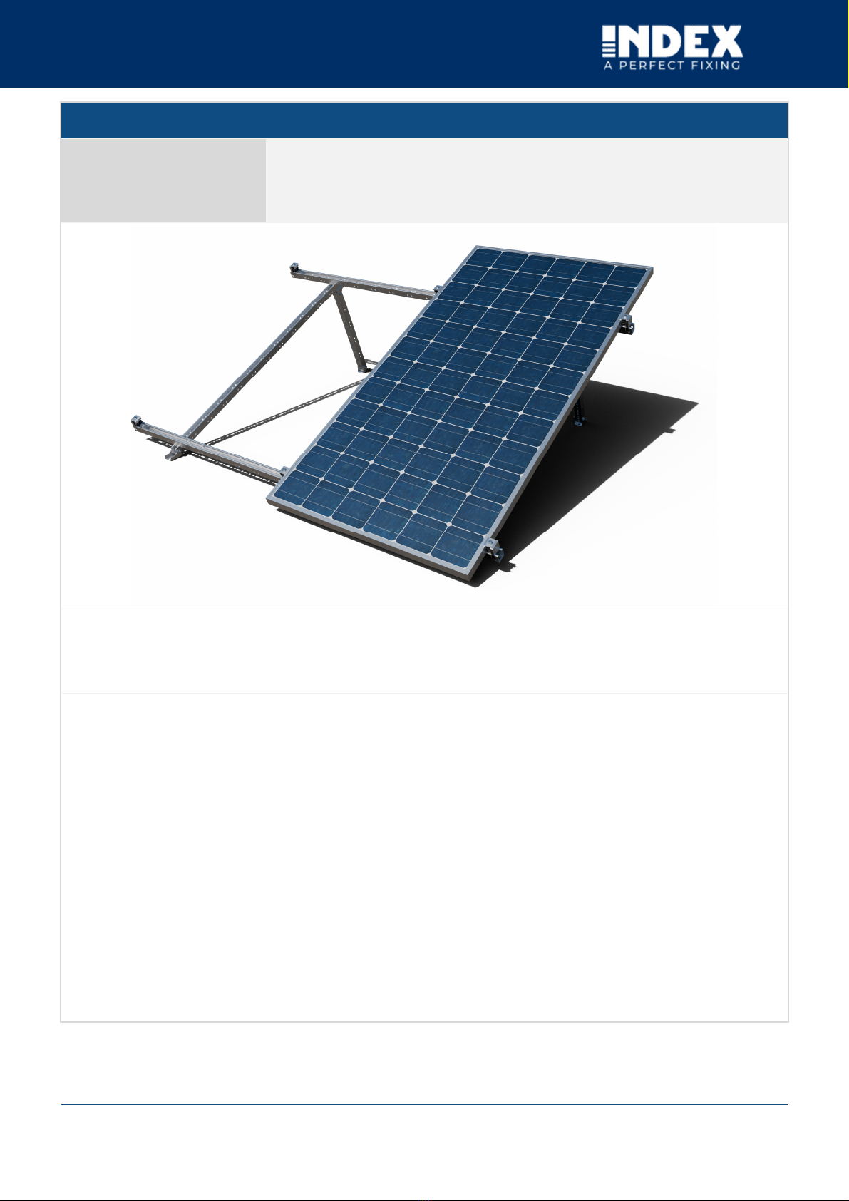
1. CHARACTERISTICS
Description:
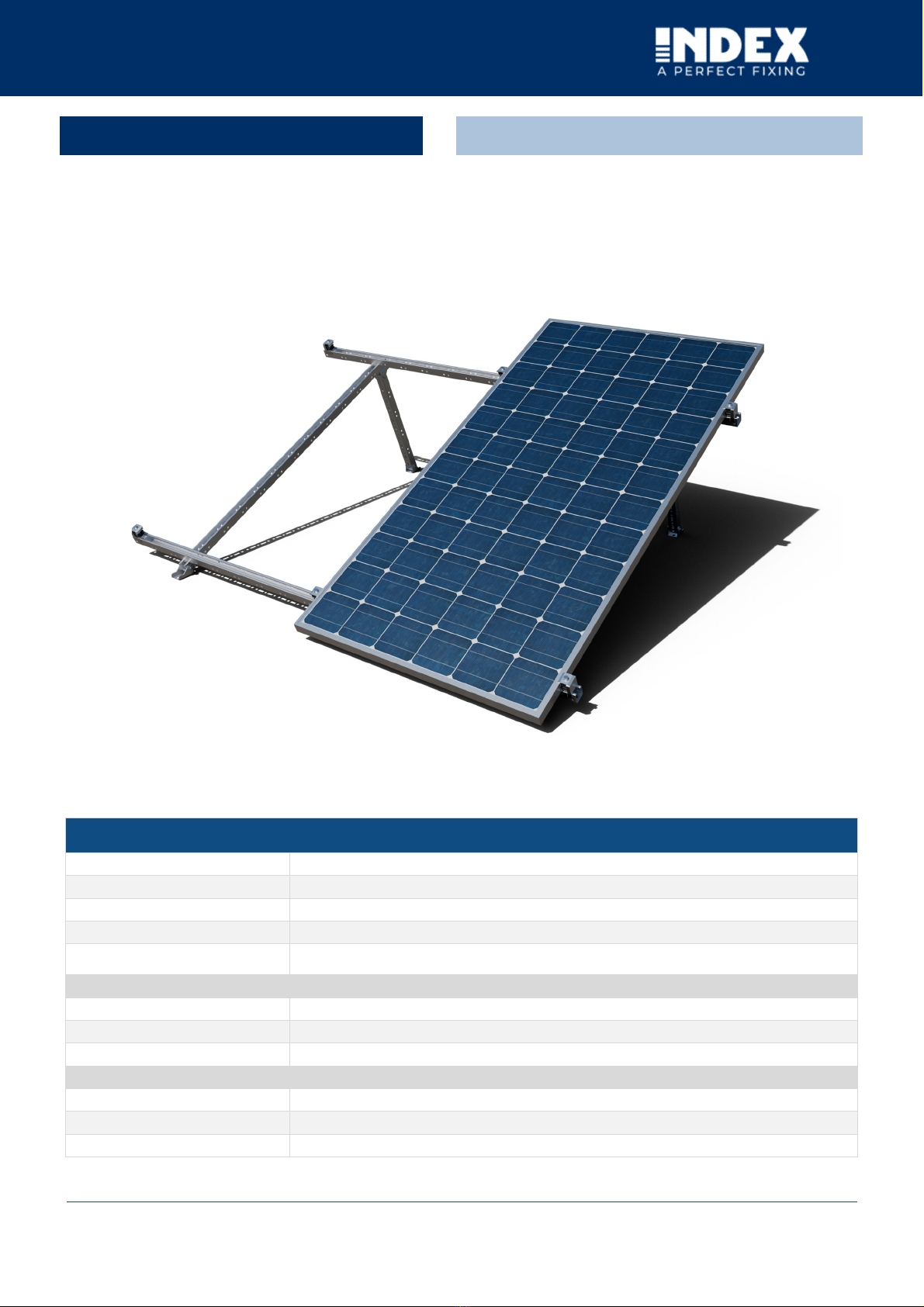
Coplanar mounting system on GP-XS Atlantis C4-M perforated guide
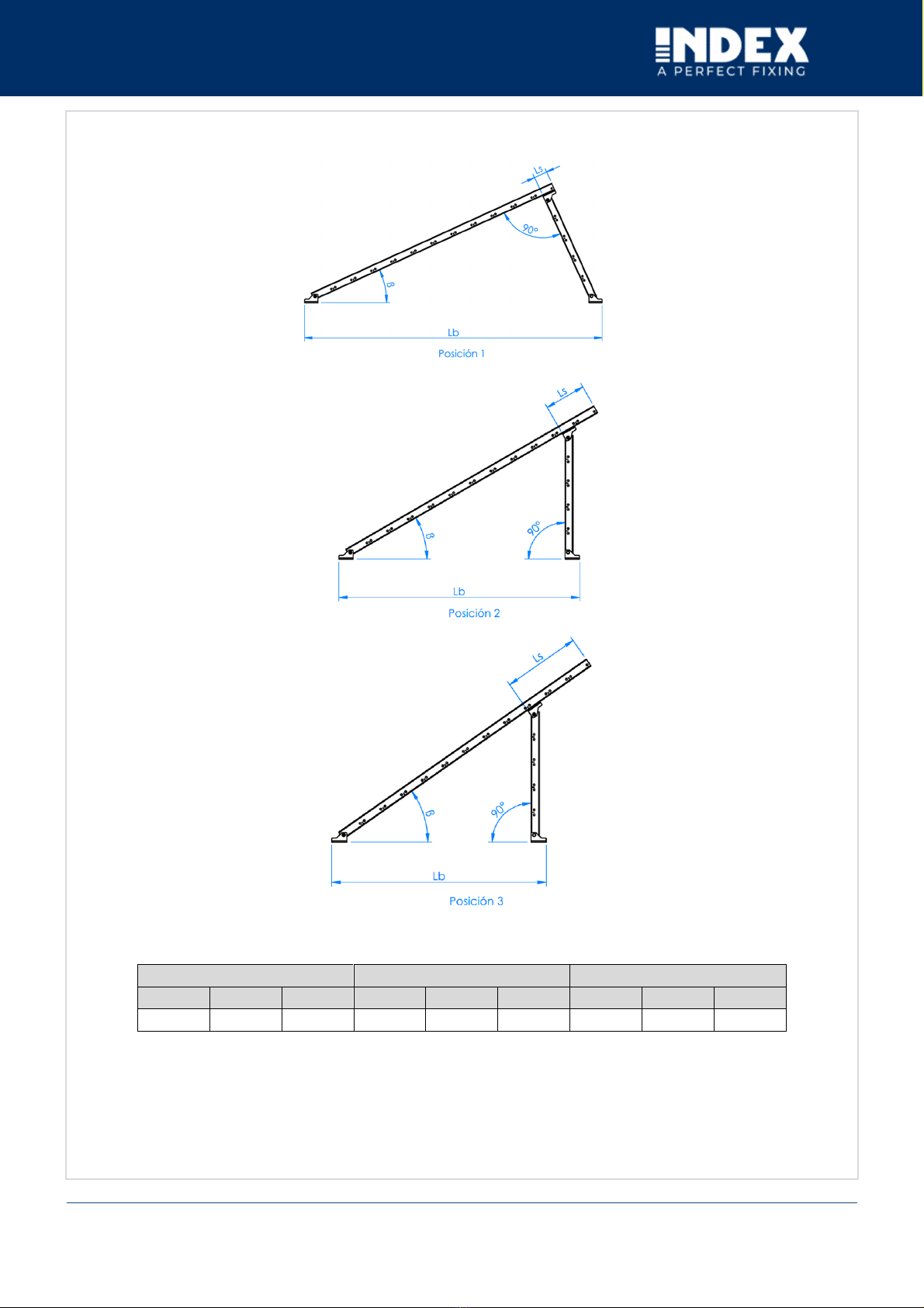
System inclination:
Triangular mounting on pre-assembled triangles with adjustable inclination at 25°, 30° and 35°.
System orientation:
Facing SOUTH, EAST OR WEST depending on the roof orientation.
System materials:
Aluminium, stainless Steel and EPDM.
Warranty:
Until 10 years depending on environmental conditions (excluding environments exposed to hydrogen
sulphide). The warranty is only valid if the complete ST-GPX system is used.
Compatible solar panels:
Solar panels type:
Solar panels with frame height between 30mm and 40mm.
Solar panels orientation:
Mounting orientation of portrait (vertical)
Solar panel size
Panel length less than 1150 mm
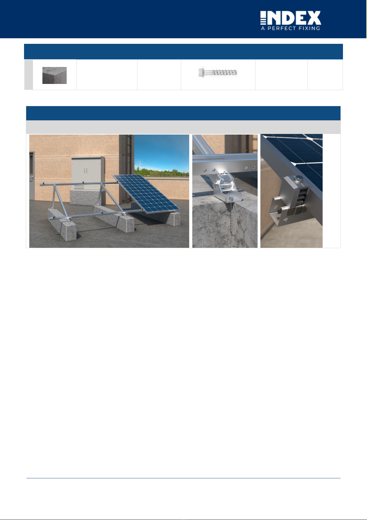
Application area:
Application area: Flat and low-slope roofs.
Roof slope: Up to 240 km/h. The structure and fixing must be calculated according to local and roof conditions.
Wind load: Up to 2 kN/m². The structure and fixing must be calculated according to local and roof conditions.
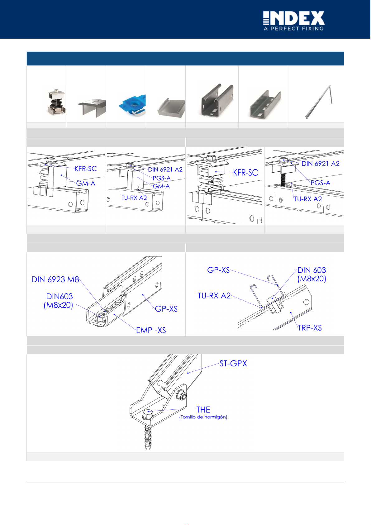
ST-GPX SYSTEM DESCRIPTION
Triangular mounting system with GP-XS “guía perforada INDEXTRUT
solar. Acero Atlantis C4-M”, para instalación de placas solares.