Indumicro IMM-L30D User manual

1
User Manual
IMM-L30D
DIN-Rail Box PC

Warning!
___________________________________
This equipment generates, uses and can radiate radio frequency energy and if not installed and
used in accordance with the instructions manual may cause interference to radio communications.
It has been tested and found to comply with the limits for a Class A computing device pursuant to
FCC Rules, which are designed to provide reasonable protection against such interference when
operated in a commercial environment. Operation of this equipment in a residential area is likely
to cause interference in which case the user at his own expense will be required to take whatever
measures may be required to correct the interference.
Disclaimer
This information in this document is subject to change without notice. In no event shall
Indumicro.com be liable for damages of any kind, whether incidental or consequential,
arising from either the use or misuse of information in this document or in any related
materials.
Electric Shock Hazard – Do not operate the machine with its back cover removed. There are
dangerous high voltages inside.
___________________________________

Table of Contents
Chapter 1: Introduction
System Specication . . . . . . . . . . . . . . . . . . . . . . . . . . . . . . . . . . . . . . . . . . . 1
Front Panel Features. . . . . . . . . . . . . . . . . . . . . . . . . . . . . . . . . . . . . . . . . . . . 2
Top and Bottom Panel Features . . . . . . . . . . . . . . . . . . . . . . . . . . . . . . . . . . . . 3
Chapter 2: Hardware Setup
Preparing the Hardware Installation. . . . . . . . . . . . . . . . . . . . . . . . . . . . . . . . . . 5
Installing the System Memory . . . . . . . . . . . . . . . . . . . . . . . . . . . . . . . . . . . . . 5
Installing a CompactFlash Card. . . . . . . . . . . . . . . . . . . . . . . . . . . . . . . . . . . . . 5
Connecting Power . . . . . . . . . . . . . . . . . . . . . . . . . . . . . . . . . . . . . . . . . . . . . 5
Chapter 3: Motherboard Information
Motherboard Layout . . . . . . . . . . . . . . . . . . . . . . . . . . . . . . . . . . . . . . . . . . . 6
Chapter 4: BIOS Settings
Boot Settings . . . . . . . . . . . . . . . . . . . . . . . . . . . . . . . . . . . . . . . . . . . . . . . .20
Security Settings . . . . . . . . . . . . . . . . . . . . . . . . . . . . . . . . . . . . . . . . . . . . . .21
Exit Menu . . . . . . . . . . . . . . . . . . . . . . . . . . . . . . . . . . . . . . . . . . . . . . . . . .22
Appendices
Programming the Watchdog Timer .. . . . . . . . . . . . . . . . . . . . . . . . . . . . . . . . .23
Digital Input/Output Control on the GPIO port . . . . . . . . . . . . . . . . . . . . . . . . . . .28
Jumper Settings . . . . . . . . . . . . . . . . . . . . . . . . . . . . . . . . . . . . . . . . . . . . . . 7
Accessing the BIOS menu . . . . . . . . . . . . . . . . . . . . . . . . . . . . . . . . . . . . . . . . 9
Navigating the BIOS menu . . . . . . . . . . . . . . . . . . . . . . . . . . . . . . . . . . . . . . . 9
Dimensions . . . . . . . . . . . . . . . . . . . . . . . . . . . . . . . . . . . . . . . . . . . . . . . . . 4
Advanced Settings . . . . . . . . . . . . . . . . . . . . . . . . . . . . . . . . . . . . . . . . . . . .20
The Main menu . . . . . . . . . . . . . . . . . . . . . . . . . . . . . . . . . . . . . . . . . . . . . .10

Introduction
Thank you for choosing the IMM-L30D. The IMM-L30D is
is an industrial computer featuring high availability and
density of serial communication and digital I/O ports in a
compact design (69.1x165x127mm[W/H/D]).
The IMM-L30D has an outstanding industrial and mechanical
design. It can be placed on the desk or mounted on the DIN-
rails to rotate along its DIN-rail attachment, thereby easing
the access of the I/O interface. This reduces maintenance
effort when the device is installed in a ticketing machine,
medical equipment, or other apparatus where access is
limited.
The IMM-L30D features a solid and sealed aluminum
extrusion housing.It provides dust resistance and superior
protection from EMI.
Here is a summary of the key capabilities of IMM-L30D:
Onboard Intel N450•
Six RS-232/422/485 ports with automatic flow control•
Four 10/100/1000 Base-T RJ-45 ports•
Four USB ports (2 external and 2 internal pin headers•
Onboard VGA interface featuring the 3rd generation•
Intel graphics core which supports resolutions up
System Specification
FEATURE
DESCRIPTION IMM-L30D
Platform
Form Factor DIN-Rail
Processor Intel N450
Chipset Intel ICH8M
BIOS AMI Flash BIOS
Memory
Memory IC On Board No
Memory Socket SODIMM x 1 (up to 2GB
per slot)
Max Memory 2GB (1 x 2GB Module)
Storage
Compact Flash
1 x CF Socket Type I/II
(internal/external options
available)
Networking
Controller (Interface) 4 x Realtek RTL8111D
I/O
COM Ports 6 x RS-232/422/485
Hardware auto-ow control
USB 2.0 2 (w/ 2 additional 2.54 pin
headers)
VGA 1 x DB15
LAN 4 x RJ45 GbE
DIDO 4 x DI, 4 x DO
Internal CF 1
Hardware
Monitor
Controller Fintek F81865F-I integrated
hardware monitor
Watchdog timer Yes (1~255 level)
OS Supported
Windows XP, Embedded XP,
Vista, 7
Environmental
Parameters
Operating Temperature
(With Industrial Components:
CF, Memory, SSD, HDD)
-20°~55°C / 14°~131°F
Operating Temperature
(With Commercial Components) -5°C~45°C / 23°~113°F
Extended Operating Tempera-
ture Tested N/A
Dimensions
W x H x D (mm) 69.1 x 165 x 127 mm
Weight 1.4Kg
Power
DC Power +12V ~ 36V DC in
Adapter 60W Adapter
Compliance
Standard CE, FCC, RoHS
Chapter 1: Introduction
IMM-L30D User Manual 1
Disk Drive 2.5 Hard Disk or Solid
"
State Disk
1.6GHz
to 1920 x 1080
Chapter 1: Introduction
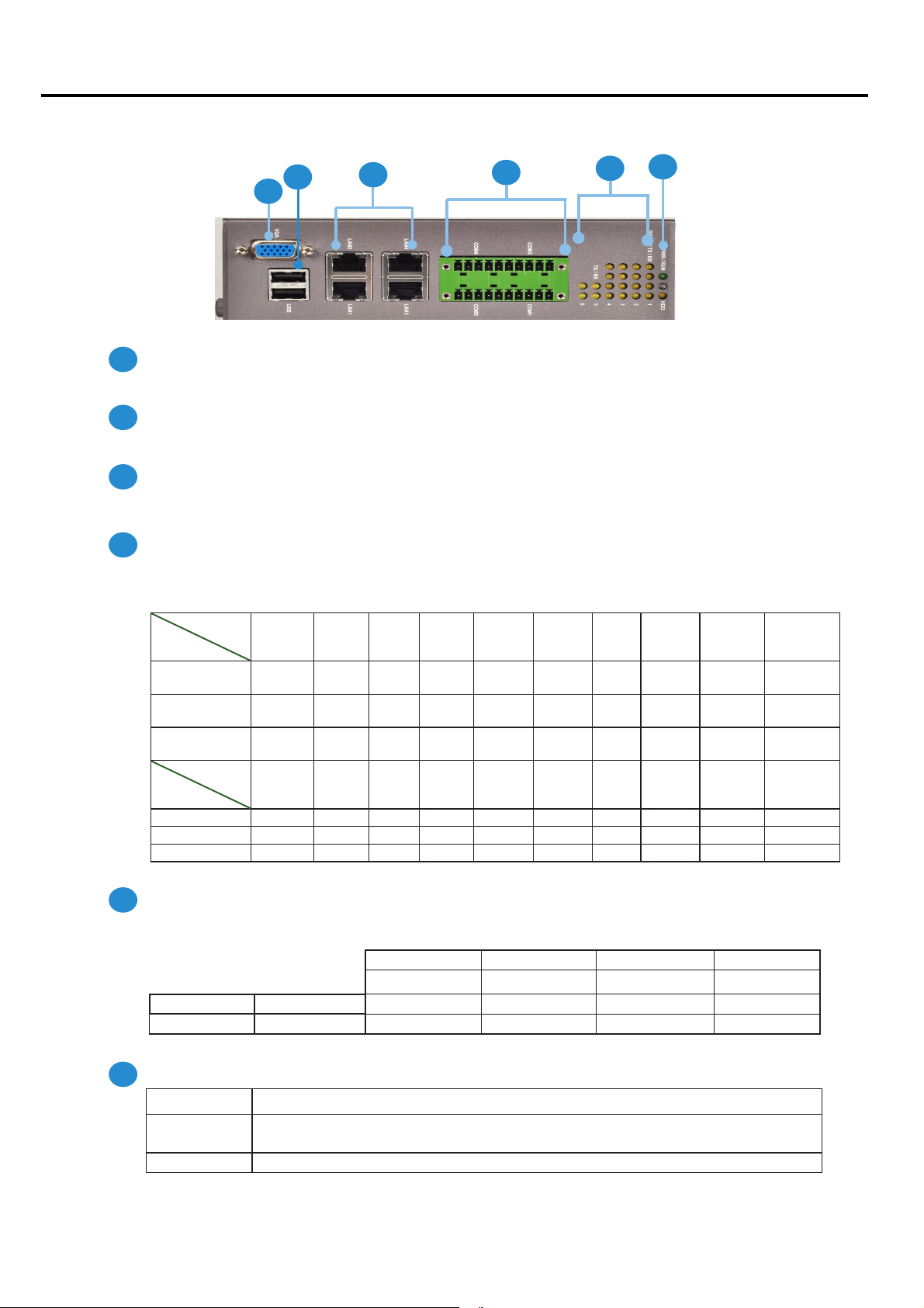
VGA Port
Port for the connection of a monitor using a suitable DB-15 cable .
Two USB 2.0 type A ports
Connects to any USB device, for example, a flash drive.
Four 10/100/1000Mbps LAN ports
Using suitable RJ-45 cable, you can connect IMM-L30D System to a computer, or to any other piece of equipment
that has an Ethernet connection such as a hub or a switch.
20-pin Phoenix Contact Terminal Block
This connector can be connected for 4 Com ports (COM4: Pin 1~5, Com3: Pin 6~10, Com2: Pin11~15, Com1: Pin
16~20) with serial port type of RS-232, RS-422 or RS-485; it supports dip switch selection of RS-232, RS-422 and
485. The following table lists the pin assignments.
Pin NO.
Port Type
Pin 1 Pin 2 Pin 3 Pin 4 Pin 5 Pin 6 PIN7 PIN 8 PIN 9 Pin10
RS-232 Ground
(GND)
CTS4# SOUT4 SIN4 RTS4# GND CTS3# SOUT3 SIN3 RTS3#
RS-422 Ground
(GND)
RX- RX+ TX+ TX- GND RX- RX+ TX+ TX-
RS-485 Ground
(GND)
NC NC DATA+ DATA- GND NC NC DATA+ DATA-
Pin NO.
Port Type
Pin 11 Pin 12 Pin 13 Pin 14 Pin 15 Pin 16 Pin 17 Pin 18 Pin 19 Pin 20
RS-232 GND CTS2# SOUT2 SIN2 RTS2# GND CTS1# SOUT1 SIN1 RTS1#
RS-422 GND RX- RX+ TX+ TX- GND RX- RX+ TX+ TX-
RS-485 GND NC NC DATA+ DATA- GND NC NC DATA+ DATA-
Serial Port Status LED
The upper two rows are LED indicators for the Digital Inputs and Outputs.
The bottom two roles are LED indicators of Tx (Data transmitting) and RX (Data receiving) for serial port Status.
Power/Status/HDD LED
Power Green indicates Power-on, where as Off indicates Power-off status.
Run A programmabledualgreen/orange LEDs which can be used for indicating
system status.
Hard Disk Yellow indicates that HDD is present, whereas Off indicates HDD is not present.
Front Panel Features
F1
F4
F3
F2
F5 F6
11121314151617181920
12345 678910
LAN1 LAN3
LAN2 LAN4
DO-Pin 4 DO-Pin 3 DO-Pin 2 DO-Pin 1
DI-Pin 4 DI-Pin 3 DI-Pin 2 DI-Pin 1
TX-COM 6 TX-COM 5 TX-COM 4 TX-COM 3 TX-COM 2 TX-COM 1
RX-COM 6 RX-COM 5 RX-COM 4 RX-COM3 RX-COM 2 RX-COM 1
F1
F2
F3
F4
F5
F6
IMM-L30D User Manual 2
Table of contents
Popular Industrial PC manuals by other brands


Dell
Dell Embedded Box PC 5000 Installation and operation manual

IBASE Technology
IBASE Technology ASB200-918 Series user manual

Lenovo
Lenovo ThinkCentre M90q Hardware Maintenance Manual

IXXAT
IXXAT Econ 100 Hardware manual

Kontron
Kontron KBox A-151-TGL user guide

AXIOMTEK
AXIOMTEK ICO500-518 Series user manual