Industrial Scientific V-CAL User manual
Part Number: 17153100-1
Version 2
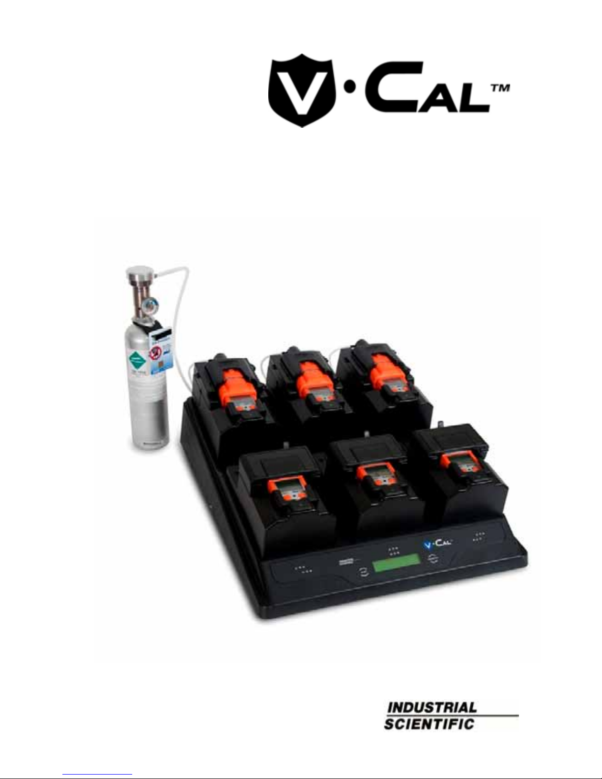
Six-Unit Calibration Station
for VentisTM
Product Manual
Set-up
Operation

Product Manual for the Six-Unit Calibration Station for Ventis™
2© 2010, 2016 Industrial Scientific Corporation
TABLE OF CONTENTS
Warnings and Cautionary Statements .................................................................. 3
Capabilities........................................................................................................... 4
Unpacking the Station .......................................................................................... 6
User Interface....................................................................................................... 7
Station Preparation............................................................................................... 8
Hardware Overview (Front) ............................................................................. 8
Hardware Overview (Back).............................................................................. 9
Software Installation and Hardware Connections .......................................... 10
Station Use......................................................................................................... 12
Power-on and -off .......................................................................................... 12
Start-up Mode................................................................................................ 12
Idle Mode....................................................................................................... 14
Set-up Mode .................................................................................................. 14
Docking and Removing the Instrument.......................................................... 20
Calibration and Bump Testing ....................................................................... 21
Status and Error Messages ........................................................................... 24
Software Use...................................................................................................... 30
Software Functions........................................................................................ 30
Using the Software ........................................................................................ 31
Diagnosing Common Problems.......................................................................... 42
Specifications ..................................................................................................... 42
Performance Specifications................................................................................ 43
Warranty............................................................................................................. 44
Contact Information ...............................................................................Back cover
###

Product Manual for the Six-Unit Calibration Station for Ventis™
© 2010, 2016 Industrial Scientific Corporation 3
WARNINGS AND CAUTIONARY STATEMENTS
WARNING: Read and understand this manual before operating the
equipment.
WARNING: Failure to perform certain procedures or note certain
conditions may impair the performance of this product. For
maximum safety and optimal performance, please read and follow
the procedures and conditions listed below.
CAUTION: For safety reasons, this equipment must be operated and
serviced by qualified personnel only.
CAUTION: Equipment is rated for indoor use only at altitudes below
2,000 m (6,000’).
CAUTION: Compressed gas cylinders and their contents may
present specific hazards to the user. Use only in a well-ventilated
area. Use only in accordance with the instructions and warnings as
marked on the cylinder and the appropriate Material Safety Data
Sheets.
NOTE: The station should be cleaned only with a soft cloth; do not
use solvents or other liquids.
NOTE: This equipment has been tested and found to comply with the
limits for a Class A digital device, pursuant to part 15 of the FCC
Rules. These limits are designed to provide reasonable protection
against harmful interference when the equipment is operated in a
commercial environment. This equipment generates, uses, and can
radiate radio frequency energy; if it is not installed and used in
accordance with the instruction manual, it may cause harmful
interference to radio communications. Operation of this equipment in
a residential area is likely to cause harmful interference in which case
the user will be required to correct the interference at the user’s own
expense.
Contact your service representative immediately if you suspect that the station is
working abnormally. ###

Product Manual for the Six-Unit Calibration Station for Ventis™
4© 2010, 2016 Industrial Scientific Corporation
CAPABILITIES
The V•CalTM is a stand-alone calibration station designed to work in conjunction
with VentisTM Multi-gas Monitors. It supports up to six instruments and is
available in three models based on cradle configuration.
Cradle configurations.
Six cradles for aspirated instruments only
Six cradles for diffusion instruments only
Three cradles for aspirated instruments only and three cradles for diffusion
instruments only
Regardless of cradle configuration, each station has three cradles on the back
row and three on the front row. As shown below, the cradles are numbered one
through six, from left to right, from front row to back row.
The station has three internal pumps. Each pump controls two cradles. For
example, as noted below, internal pump 1 controls cradles 1 and 4.
Cradle numbe
r
Back row 4 5 6
Front row 1 2 3
Internal pump 1 2 3
Each internal pump has a solenoid that controls the flow of gas (and fresh air) to
the cradles. These solenoids are referred to in this manual as “cradle solenoids”.
A fourth solenoid, referred to as the “gas solenoid”, controls the flow of calibration
gas and fresh air from the station's intake ports.
The station communicates directly with up to six docked instruments to perform
bump tests and calibrations. It can also charge up to six instruments equipped
with rechargeable Lithium-ion (Li-ion) battery packs.
Calibration and bump test records are saved to the station’s memory which can
store a total 12,000 records. The results for each calibration and bump test
performed are automatically sent, in report form, to an external serial printer (via
an RS232 connection) when connected.
The station can communicate with a host PC across a USB connection, when the
PC is running Accessory Software. The following capabilities are included in the
calibration station with respect to commands from the host PC.

Product Manual for the Six-Unit Calibration Station for Ventis™
© 2010, 2016 Industrial Scientific Corporation 5
Accessory Software enabled capabilities for the host PC.
Read and write instrument and calibration station settings.
Read the instrument data log.
Read the instrument event log.
Access bump test and calibration records from the station.
The following operating systems support Accessory Software:
Windows XP
Windows Vista
Windows 7
Windows 8
###
Table of contents
Other Industrial Scientific Test Equipment manuals

Popular Test Equipment manuals by other brands


Redtech
Redtech TRAILERteck T05 user manual

Venmar
Venmar AVS Constructo 1.0 HRV user guide

Test Instrument Solutions
Test Instrument Solutions SafetyPAT operating manual

Hanna Instruments
Hanna Instruments HI 38078 instruction manual

Kistler
Kistler 5495C Series instruction manual

Waygate Technologies
Waygate Technologies DM5E Basic quick start guide

StoneL
StoneL DeviceNet CK464002A manual

Seica
Seica RAPID 220 Site preparation guide

Kingfisher
Kingfisher KI7400 Series Training manual

Kurth Electronic
Kurth Electronic CCTS-03 operating manual

SMART
SMART KANAAD SBT XTREME 3G Series user manual

Agilent Technologies
Agilent Technologies BERT Serial Getting started