Tesmec DLR300 User manual

P
P
U
L
L
L
R
D
R
E
C
D
LR
3
U
S
M
A
C
O
R
3
00
S
ER
A
N
U
R
D
E
U
AL
E
R
English


A
lw
a
any
a
ys quote
informatio
P
Y
e
the Mode
n regardin
g
P
ULL
Mo
d
Se
r
……
e
ar o
f
……
Or
d
……
l, Year of
g
the instr
u
Page
RE
C
d
el:
D
r
ial n
……
f
ma
n
……
d
er n
u
……
manufact
u
u
ment (us
e
III
C
OR
D
D
LR
3
um
b
……
…
n
ufa
c
……
…
u
mb
e
……
…
u
re and
O
e
, mainten
D
ER
3
00
b
er
…
.
c
tur
e
…
.
e
r
…
.
O
rder num
b
ance and
s
e
b
er when
r
s
pare part
s
r
equestin
g
s
).
g

Page IV
⇒Do not bend, twist or apply excessive pressure to the power cable.
The internal wires may become uncovered or be damaged.
⇒Do not modify the power cable.
⇒Do not pull the cable to disconnect it.
⇒Do not place heavy objects on the power cable.
⇒Keep the power cable away from sources of heat.
⇒Be careful not to get caught up in the power cable.
⇒Clean the connectors regularly. If the connectors are covered in
dust or exposed to humidity, the insulation can deteriorate and
cause the recorder to malfunction.
Do not place the recorder near sources of heat, in excessively dusty
environments or where it will be subject to mechanical shocks.
Handle the power cable and connectors as indicated below so as to
prevent electrical shock or damage:
Carefully read all the instructions in this manual before connecting,
using or configuring this product.
TESMEC S.p.A. reserves the right to make technical and constructive
changes to the DLR300 without prior notice and if deemed necessary

Page V
1. GENERAL INDEX Page
1.GENERAL INDEX V
2.GENERAL INFORMATION AND REQUIREMENTS 1
2.1MANUFACTURER 1
2.2TYPE AND FIELD OF USE 1
2.3PARTS GUIDE 2
2.3.1UPPER PANEL 2
2.3.2REAR PANEL 3
2.3.3STANDARD ACCESSORIES 3
2.4INTERNAL MEMORY 4
2.5POWER SUPPLY 4
2.6APPLIED REGULATION 4
3.USING THE RECORDER 5
3.1POSITIONING AND CONNECTING TO THE MACHINE 5
3.2SWITCH-ON 5
3.3ACCESS TO THE MAIN MENU 6
3.4SETTING THE WORK PARAMETERS 6
3.4.1SETTING THE ROPE DIAMETER 6
3.4.2SETTING THE SAMPLING 7
3.4.3SETTING THE LIMIT VALUE 7
3.4.4SETTING THE TYPE OF PRINT 7
3.4.5SETTING THE UNITS OF MEASUREMENT 7
3.4.6SETTING THE LANGUAGE 8
3.5SETTING THE CLOCK 8
3.5.1SETTING THE DAY 8
3.5.2SETTING THE DATE 8
3.5.3SETTING THE MONTH 8
3.5.4SETTING THE YEAR 9
3.5.5SETTING THE HOURS 9
3.5.6SETTING THE MINUTES 9
3.5.7SETTING THE SECONDS 9
3.6SETTING THE DISPLAY CONTRAST 9
3.7BEGINNING AND END OF THE MONITORING PROCESS 10
3.8FULL MEMORY 12
3.9MANAGING SAVED AND PRINTED CABLE LAYING OPERATIONS 12
3.9.1DISPLAY CABLE LAYING OPERATIONS 13
3.9.2PRINT CABLE LAYING OPERATIONS 13
3.9.3SAVING AN INDIVIDUAL CABLE LAYING PROCESS 14
3.9.4SAVING ALL THE CABLE LAYING OPERATIONS 15
3.9.5DELETING AN INDIVIDUAL CABLE LAYING PROCESS 16
3.9.6DELETING ALL THE CABLE LAYING OPERATIONS 16
3.10REPLACING THE PAPER ROLL. 17
ATTENTION! 18
4.SETTING CONSTANTS AND CALIBRATIONS 19
4.1STEPS TO SET CONSTANTS AND CALIBRATIONS 19
4.1.1SETTING THE COMPANY NAME 19
4.1.2SETTING THE DIGITAL PARAMETERS 19
4.1.3SETTING THE ANALOGUE PARAMETERS 21
4.1.4SETTING THE FUNCTIONAL PARAMETERS 23
4.1.5SETTING THE CALIBRATIONS 24
4.1.6SETTING THE SERIAL NUMBER 27
4.1.7SETTING THE COUNTER 27
4.2CONFIGURATION MANAGEMENT PROCEDURE 28
4.2.1RESTORE FROM A PEN DRIVE 28
4.2.2WRITE TO A PEN DRIVE 28
4.2.3PRINT CONFIGURATION 29
4.2.4LOADING A NEW LANGUAGE 31
4.2.5RESTORING THE DEFAULT CONFIGURATION 31
5.MANAGING ERRORS 32
5.1ERROR 1 – CHECK GENERAL PARAMETERS 32
5.2ERROR 2 – EPROM ERROR 32

Page VI
5.3ERROR 4 – ENCODER CONSTANT CALCULATION 32
5.4ERROR 5 – SPAN BIT ERROR 32
5.5ERROR 6 – SPAN PULL ERROR 32
5.6ERROR 7 – FULL SCALE ERROR 32
6.FIRMWARE UPDATE 33
6.1INSTALLATION GUIDE OF THE BOOTLOADER DLR300 33
6.1.1MINIMUM SYSTEM REQUIREMENTS 33
6.1.2INSTALLING THE USB DRIVERS 33
6.1.3INSTALLING THE SOFTWARE 35
6.2BOOTLOADER DLR300 USER GUIDE 39
6.2.1SOFTWARE FUNCTIONS 39
6.2.2RUNNING THE PROGRAMME 39
6.2.3INSTALLING THE FIRMWARE 40
6.2.4INSTALLING A NEW LANGUAGE 42
7.SPARE PARTS 43

2. GENERAL INFORMATION AND REQUIREMENTS
2.1 MANUFACTURER
TESMEC S.p.A.
Via Zanica, 17/O
24050 - GRASSOBBIO
BG - ITALY
tel. (+39)-035-4232911
fax (+39)-035-4522445
e-mail: [email protected]
Via Pertegalli, 2
24060 - ENDINE GAIANO
BG - ITALY
tel. (+39)-035-825024
fax (+39)-035-826375
2.2 TYPE AND FIELD OF USE
The DLR300 pull recorder is an electronic device that monitors and records the stringing
parameters of overhead lines or the laying of underground lines.
The following characteristic data is displayed in real time:
- cable stringing/laying length
- the pull value applied with confirmation of a pre-set limit value being exceeded
- instantaneous speed of cable stringing/laying
the data is saved simultaneously with the following:
- date and time monitoring begins
- pull limit value that must not be exceeded
- sampling interval
- date and time monitoring ends.
The DLR300 can record and save the data of individual cable stringing or laying operations in its
internal memory. The saved data can be recalled at a later stage to be printed or exported to a
USB flash device. The data exported to a USB flash device can then be downloaded and viewed
on any Personal Computer.
The DLR300 recorder can be configured with the parameters of the machine it will be connected
to, using the USB flash device. This procedure allows the DLR300 to be connected to machines
with different features, by transferring the relative configuration parameters to the recorder.
In the DLR300 pull recorder and manual, "CABLE LAYING" refers to both "stringing" and "laying"
operations.
ATTENTION:
We cannot guarantee compatibility with all USB flash drives on the market.
The DLR300 recorder can monitor and save the data of individual cable stringing
or laying operations of the machines it is connected to but cannot intervene on
their operation.

Page 2
2.3 PARTS GUIDE
2.3.1 UPPER PANEL
DISPLAY: Backlit LCD with 8 rows of 24 characters each.
TYPE-A USB FLASH SOCKET
PRINTER: Thermal, which allows the real time cable laying data to be printed or recalled
from the internal memory of the recorder.
FUNCTION BUTTONS: These are the controls that provide access to the recording
programme and the management menus of the cable stringing or laying operations:
4
12 3
1
2
3
4
START/STOP BUTTON: Press this button twice to start or stop the pull recording
operations
+ BUTTON: This allows the user to scroll the functions of a menu, choose from the
o
p
tions available or enter al
p
hanumeric values
- BUTTON: This allows the user to scroll the functions of a menu, choose from the
o
p
tions available or enter al
p
hanumeric values
SEL BUTTON: This provides access to the management menus and is also used to
confirm and save the data entered
ESC BUTTON: This allows the user to exit the menus and to exit without saving after
havin
g
chan
g
ed parameters.
Page 3
The and buttons are used to increase or decrease a numerical value, as
follows:
¾briefly press one of the two buttons to change the numerical value by
one unit each time
¾keep one of the two buttons pressed for the numerical value to change as
follows:
•by one unit up to 10
•it then changes in 10s up to 100
•then in 100s up to 1000
•then in 1000s up to 10,000
Release the pressed button once the desired value is reached. If the numerical
value must be corrected, repeat the steps described above.
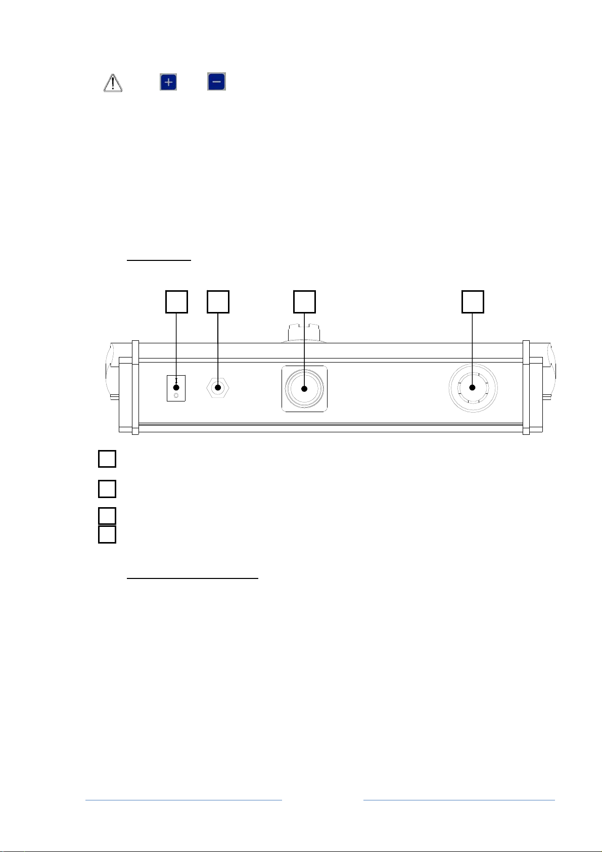
2.3.2 REAR PANEL
ON BUTTON: main switch
POWER INPUT: socket for the multi-voltage plug
16-PIN FEMALE CIRCULAR CONNECTOR: socket for the machine interface cable
TYPE-B USB SOCKET: to update the firmware or to add optional languages.
2.3.3 STANDARD ACCESSORIES
BOX: to transport the DLR300
WIRE: to connect the DLR300
PLUG: multi-voltage plug
USB FLASH DRIVE
TRANSPARENT POCKET: to protect the DLR300 in case of rain
PAPER ROLL: to print the cable laying operations
1 2 3 4
3
2
1
4

2.4
The int
e
rows of
¾
¾
Refer to
¾
¾
2.5
The DL
R
machin
e
2.6
The pull
2004/1
0
INTERNAL
e
rnal memor
y
information
t
The "cable l
a
The “rows o
f
number, da
t
applied and
been invert
e
the printout
“cable layin
g
it consists o
f
POWER SU
R
300 pull re
c
e
it is conne
c
APPLIED R
recorder is
b
0
8/EC Elect
r
2
MEMORY
y
of the DLR
3
t
hat are prin
t
a
ying opera
t
f
informatio
n
t
a such as th
warnings of
e
d, etc.
below to un
d
g
” started at
f
24 rows of
PPLY
c
order is de
s
c
ted to or fro
m
EGULATIO
N
b
uilt in com
p
r
omagnetic
C
1
3
00 can sav
e
t
ed on pape
r
t
ion" is the i
n
n
" are the se
t
e speed, le
n
the maximu
d
erstand th
e
14:29 and s
t
information
s
igned to fun
c
m
an extern
a
N
p
liance with t
C
ompatibility
Page 4
e
64 cable l
a
r
.
n
terval betw
e
t
of entries b
e
n
gth of the c
a
m pull havin
g
e
above des
c
t
opped at 14
c
tion with 1
2
a
l source, s
u
he following
Directive.
a
ying operati
e
en the begi
n
e
aring the c
o
a
ble itself an
d
g
being exc
e
c
riptions bett
e
:30
2
V - 24Vdc d
u
pplied as st
a
directive:
ons, each o
n
n
ning and e
n
o
mpany na
m
d
the actual
e
eded, the di
e
r:
irectly draw
n
a
ndard.
n
e with 4,09
6
n
d of a recor
d
m
e, the serial
pull value
rection havi
n
n
from the
6
d
ing
n
g

Page 5
3. USING THE RECORDER
3.1 POSITIONING AND CONNECTING TO THE MACHINE
Connect the DLR300 to the machine that is to be monitored, using the wire supplied together with
the recorder.
Implement the electrical connections between the recording unit and the machine with
the engine switched off so as to prevent interference with the instruments.
ATTENTION: it is recommended to use the instrument on machines that pull back
the rope so as to detect the max. pull applied on the line.
3.2 SWITCH-ON
Switch the instrument on from the ON/OFF selector on the rear panel of the recording unit.
The serial number, version, date of the software and the checksum of the EPROM will appear on
the display for a few seconds when the instrument is switched on.
Serial number: x
V. x. x [dd.mm.yy] Ck:xxxx
Where:
⇒Serial number = the serial number of the instrument
⇒V.x.x = version of the software installed
⇒[dd.mm.yy] = the date when the software was created
⇒Ck: xxxx = checksum
If the DLR300 malfunctions, the version of the software and its checksum must be
communicated
After a few seconds, the current day, date and time appear on the display:
dd dd/mm/yy hh:mm
Where:
⇒dd = day of the week
⇒dd = day – mm = month – yy = year
⇒hh = hour – mm = minutes

Page 6
ATTENTION: press the button to activate or deactivate the screen light.
ATTENTION: if the machine is used at low temperatures, the sensor and the pull
recorder must be connected and electrically switched on for approx. 15 min before
implementing any operation.
The various functions can then be accessed via the keyboard.
3.3 ACCESS TO THE MAIN MENU
To access the management menu of the instrument, when the current date and time appear on
the display:
&Press: for a few seconds
The following appears: RECORDINGS MANAGEMENT
WORK PARAMETERS
MACHINE PARAMETERS
SETTING THE CLOCK
DISPLAY CONTRAST
CONFIGURATION MANAGEMENT
The instrument displays a menu to manage recordings and parameters. To access the desired
option:
&Press: to select the next function
or
&Press: to select the previous function
or
&Press: to access the selected function
or
&Press: to exit the main menu and return to the initial display (current
date and time).
3.4 SETTING THE WORK PARAMETERS
The parameters pertaining to a correct reading must be entered before each recording. This
programming level requires the user to access the main menu, then:
&Press: or to navigate the menu and select the WORK
PARAMETERS function
♦Select: WORK PARAMETERS
&Press: to access the configuration page of the work parameters;
The following appears: CABLE DIAMETER (mm):
SAMPLING (m):
PULL LIMIT VALUE (daN):
PRINT IN REAL TIME:
MEASUREMENTS:
LANGUAGE:
3.4.1 SETTING THE ROPE DIAMETER
♦Select: CABLE DIAMETER (mm): 10.0 (or another pre-set value) is the
diameter of the rope or conductor expressed in mm with one
decimal place.
&Press: or until the desired value is selected.

Page 7
ATTENTION: the values range from 1.0 to the pre-set value in the
MAX ROPE DIAM. (mm) item (refer to Chap 4.1.2.2).
&Press: to confirm the selection and move on to the next work parameter
or
&Press: to return to the main menu without saving any changesmade.
3.4.2 SETTING THE SAMPLING
♦Select: SAMPLING (m): 10 (or another pre-set value) is the recording step in
metres, i.e. the data will be read every given number of metres of
cable and will be saved and printed
&Press: or until the desired value is selected.
ATTENTION: the values range from 1 to 100 m
&Press: to confirm the selection and move on to the next work parameter
or
&Press: to return to the main menu without saving any changes made.
3.4.3 SETTING THE LIMIT VALUE
♦Select: PULL LIMIT VALUE (daN): 4000 (or another pre-set value) is the
threshold value of the applied pull, in daN, above which the
instrument alarm status is triggered.
&Press: or until the desired value is selected.
ATTENTION: the values range from 1 to the pre-set value in the
FULL SCALE (daN) item (refer to Chap 4.1.3.2).
&Press: to confirm the selection and move on to the next work parameter
or
&Press: to return to the main menu without saving any changes made.
3.4.4 SETTING THE TYPE OF PRINT
♦Select: PRINT IN REAL TIME: No (or Yes). If NO is selected, the recorded
data will be saved to possibly be printed at a later stage, whereas if
YES is selected, the instrument will print the report in real time while
the machine is running.
&Press: or to select the desired value.
&Press: to confirm the selection and move on to the next work parameter
or
&Press: to return to the main menu without saving any changes made.
3.4.5 SETTING THE UNITS OF MEASUREMENT
♦Select: MEASUREMENTS: Metric (or Imperial)
&Press: or until the desired units are selected.
&Press: to confirm the selection and move on to the next work parameter
or
&Press: to return to the main menu without saving any changes made.
Page 8
3.4.6 SETTING THE LANGUAGE
♦Select: LANGUAGE: English (or any other language available)
&Press: or until the desired language is selected.
All the screens displayed and printouts will be in the selected
language.
&Press: to confirm the selection and return to the main menu
or
&Press: to return to the main menu without saving any changes made.
3.5 SETTING THE CLOCK
To change the date and time of the unit, access the main menu, then:
&Press: or to navigate the menu and select the CLOCK
SETTINGS function
♦Select: SETTING THE CLOCK
&Press: to access the clock adjustment page
The following appears: CLOCK ADJUSTMENT
Day:
Date:
Month:
Year:
Hours:
Minutes:
Seconds:
3.5.1 SETTING THE DAY
♦Select: Day: dd
&Press: or to select the desired day.
&Press: to confirm the selection and move on to the next setting
or
&Press: to return to the main menu without saving any changes made.
3.5.2 SETTING THE DATE
♦Select: Date: dd
&Press: or to select the correct date.
&Press: to confirm the selection and move on to the next setting
or
&Press: to return to the main menu without saving any changes made.
3.5.3 SETTING THE MONTH
♦Select: Month: mm
&Press: or to select the correct month.
&Press: to confirm the selection and move on to the next setting
or
&Press: to return to the main menu without saving any changes made.

Page 9
3.5.4 SETTING THE YEAR
♦Select: Year: yy
&Press: or to select the correct year.
&Press: to confirm the selection and move on to the next setting
or
&Press: to return to the main menu without saving any changes made.
3.5.5 SETTING THE HOURS
♦Select: HOURS: hh
&Press: or to select the correct hour.
&Press: to confirm the selection and move on to the next setting
or
&Press: to return to the main menu without saving any changes made.
3.5.6 SETTING THE MINUTES
♦Select: Minutes: mm
&Press: or to select the correct minutes.
&Press: to confirm the selection and move on to the next setting
or
&Press: to return to the main menu without saving any changes made.
3.5.7 SETTING THE SECONDS
♦Select: Seconds: ss
&Press: or to select the correct seconds.
&Press: to confirm the selection and return to the main menu
or
&Press: to return to the main menu without saving any changes made.
3.6 SETTING THE DISPLAY CONTRAST
To change the display contrast, in order to improve readability in different lighting conditions,
access the main menu:
&Press: or to navigate the menu and select the DISPLAY CONTRAST
function
♦Select: DISPLAY CONTRAST
&Press: to access the display contrast adjustment page
The following appears: Contrast: 50% (or another pre-set percentage)
&Press: or until the desired percentage is selected.
&Press: to confirm the selection
or
&Press: to return to the main menu without saving any changes made.
Page 10
3.7 BEGINNING AND END OF THE MONITORING PROCESS
To begin the monitoring process, when the current date and time appear on the display:
&Press: twice and fast
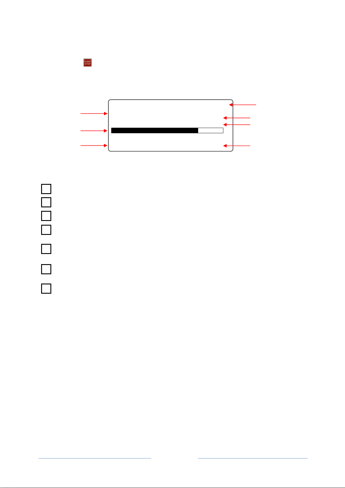
The following screen appears on the display, which corresponds to the data recording mode of
the instrument:
XXXX Fm: xxxx
REC. x
daN Nor.
XXXX mX.X km/h
where:
F= applied pull (in daN - lbf)
Fm = control pull limit value (in daN - lbf)
REC. = the recording number
Func. = operation mode of the hydraulic motor, normal or reduced, if the rpm reducer of the
motor is activated (only on machines equipped with this device)
A bar that visually indicates the difference between the instantaneous value of the applied
pull and the limit value
D= cable laying distance (in m - ft), which can be either a positive or negative value,
depending on the direction of the cable laying operations
V= cable laying speed (in km/h – ft/min).
1
2
3
4
7
6
5
1
5
6
2
3
4
7
Thi
s
prin
t
wh
e
3
4
5
6
7
1
2
8
9
1
0
11
s
data is sa
v
t
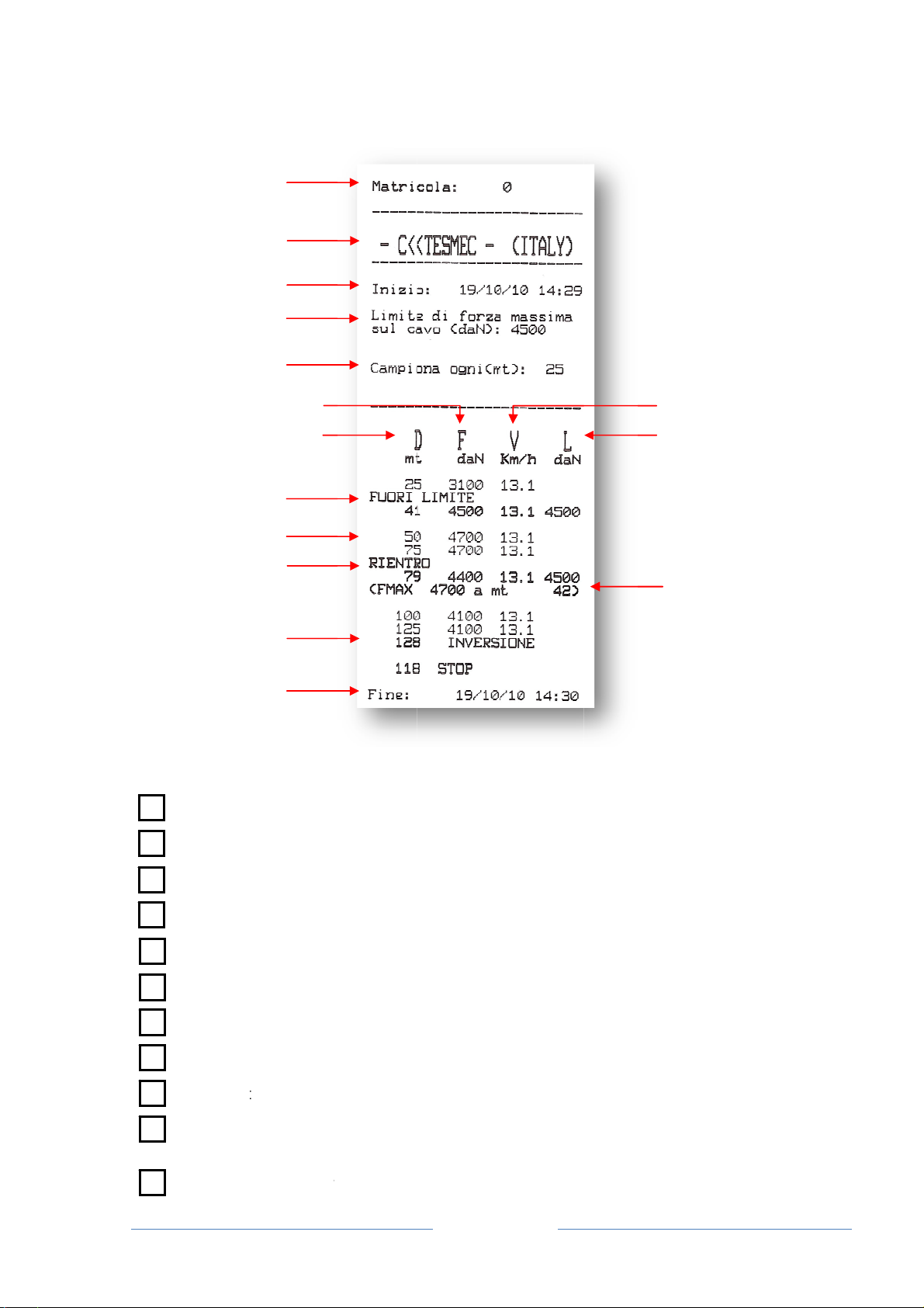
out will be
s
e
re:
serial n
u
compan
date an
d
set pull
l
samplin
g
D = cab
l
F = app
l
V = cab
l
L = con
t
length,
p
samplin
g
any sa
m
v
ed by the
i
s
imilar to the
u
mber of the
y name
d
time monit
o
l
imit value (i
n
g
interval (in
l
e laying dis
t
l
ied pull (in
d
l
e laying spe
t
rol pull limit
v
p
ull and sp
e
g
step)
m
plings reco
r
1
2
3
4
5
6
7
10
11
12
14
15
i
nstrument
a
example be
l
pull recorde
o
ring begins
n
daN - lbf)
m – ft)
t
ance (in m
–
d
aN - lbf)
ed (in km/h
–
v
alue (in da
N
e
ed corresp
o
r
ded in alar
m
Pag
e
a
nd can be
l
ow:
r
–
ft)
–
ft/min)
N
- lbf)
o
nding to t
h
m
conditions
e
11
printed in r
e
h
e initial ala
r
e
al time or
a
r
m conditio
n
9
8
a
t a later st
a
n
s (regardle
s
9
8
1
a
ge. The
s
s of the

Page 12
length, pull and cable laying speed corresponding to the final alarm conditions
max pull value reported during the alarm conditions and corresponding cable laying
distance
cable laying length corresponding to the inverted direction conditions
date and time monitoring ends
ATTENTION: Should the paper finish while printing in real time, the device will save
the samples to print them when the paper will be replaced.
The pull limit value L can be modified during the data monitoring process by an amount equal to
that pre-set in the LIMIT CHANGE item (Chap 4.1.3.3); to do so:
&Press: or to increase or decrease the control limit.
Clearly, if the pre-set value in the LIMIT CHANGE item is equal to “0” (zero) there will be no
change in the control limit value.
To end the monitoring process:
&Press: twice and fast
and the current date and time will appear on the display once again.
If the instrument should be unintentionally switched off during the monitoring process, perform the
following steps after switching it back on and when the current date and time appear on the
display:
&Press: twice and fast
and the instrument will continue recording the cable laying operations as from when the
instrument was switched off.
3.8 FULL MEMORY
If the memory available for an individual cable laying process should be less than 10% during the
monitoring process, the message: REC. : xxx % will appear on the display instead of the
recording number where xxx indicates the amount of memory actually used.
In this case, it is recommended to complete the cable laying operations as soon as possible and
start a new recording, deleting the recordings of unnecessary cable laying operations.
The instrument saves 64 cable laying operations and when this value is reached, the DLR300 will
write the subsequent operations restarting from the first, overwriting the data saved previously. It
is therefore recommended to print or download the saved cable laying operations on a daily basis,
deleting them from the memory so as to prevent unpleasant management problems.
3.9 MANAGING SAVED AND PRINTED CABLE LAYING OPERATIONS
To access the management procedure of the saved and printed cable laying operations, access
the main menu, then:
&Press: or to navigate the menu and select the RECORDINGS
MANAGEMENT function
♦Select: RECORDINGS MANAGEMENT
&Press: to access the recorded cable laying management page
The following appears: DISPLAY RECORDING
PRINT RECORDING
SAVE RECORDING
SAVE ALL RECORDINGS
DELETE RECORDING
DELETE ALL RECORDINGS
12
14
1
5
1
3
Page 13
3.9.1 DISPLAY CABLE LAYING OPERATIONS
&Press: or to navigate the cable laying management menu and
select the DISPLAY RECORDING function
♦Select: VIEW RECORDING
&Press: to access the display page of the recorded cable laying operations
The following appears: VIEW RECORDING
N:xx dd.mm.yy. hh:mm
END: dd.mm.yy. hh:mm
&Press: or until the desired cable laying operation is selected.
&Press: to confirm the selection
or
&Press: to exit the display page and return to the cable laying
management page.
The instrument displays the recorded data in sequence. To move the display forward or
backward:
&Press: or
Once viewing is complete:
&Press: to exit the display page and return to the cable laying
management page.
3.9.2 PRINT CABLE LAYING OPERATIONS
&Press: or to navigate the cable laying management menu and
select the PRINT RECORDING function
♦Select: PRINT RECORDING
&Press: to access the print page of the cable laying operations
The following appears: PRINT RECORDING
N:xx dd.mm.yy. hh:mm
END: dd.mm.yy. hh:mm
&Press: or until the cable laying operation to be printed is selected.
&Press: to confirm the selection
or
&Press: to exit the display page and return to the cable laying
management page.
To stop printing:
&Press: to exit printing and return to the cable laying management page.
To see how the data will be printed, refer to paragraph 3.7.
Once the data is printed, the instrument asks the user whether the graph should also be printed:
The following appears: PRINT THE GRAPH? NO
&Press: or until YES is selected to print the graph
or
&Press: or until NO is selected for the graph not to be printed.
&Press: to confirm the selection made
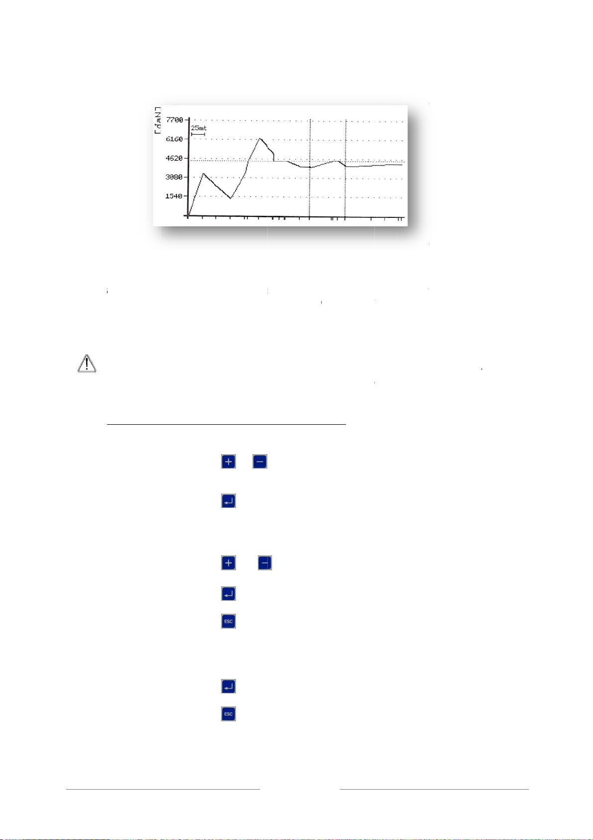
The pri
n
The me
indicate
s
vertical
a
necess
a
pull limi
t
triggere
d
line alo
n
A
t
s
3.9.3
The rec
o
access
t
&Pres
s
♦Sele
c
&Pres
s
Th
e
&Pres
s
&Pres
s
&Pres
s
Th
e
Insert t
h
&Pres
s
&Pres
s
Th
e
n
ter will provi
tres covere
d
s
the positio
n
a
xis: the axi
s
a
rily the ma
x
t
having bee
n
d
due to th
e
n
g the entire
A
TTENTION
rend in th
e
s
izes (in nu
m
SAVING AN
o
rdings of th
t
his function
:
s
:
c
t:
s
:
e
following a
p
s
:
s
:
s
:
e
following a
p
h
e USB stick
s
:
s
:
e
following a
p
de a similar
d
are show
n
n
s in which
a
s
is sized s
o
x
pre-set co
n
n
exceeded,
e
limit havin
g
graph.
: the graph
e
cable layi
n
m
bers), the
INDIVIDU
A
e cable layi
n
:
p
pears:
p
pears:
into the rela
p
pears:
O
P
graph to tha
n
on the ho
r
a
n inverted
d
o
as to repre
s
n
trol limit. T
h
this limit wil
g
been exce
provides
a
n
g operati
o
user must
r
A
L CABLE L
A
n
g operation
s
or
select the
S
SAVE RE
C
to acc
e
operation
SAVE RE
C
N:xx dd.
m
END: dd.
m
or
selected.
to con
f
or to exi
managem
e
INSERT T
H
tive slot fou
n
or star
t
or to retu
r
O
PERATIO
N
P
LEASE W
A
Page 14
t shown bel
o
r
izontal axis
d
irection occ
u
s
ent the ma
x
h
erefore, if n
o
l not appea
r
eded, the li
m
a
qualitativ
e
o
ns. Howev
e
r
efer to the
n
A
YING PRO
C
s
carried ou
t
to navigate
S
AVE REC
O
C
ORDING
e
ss the pag
e
C
ORDING
m
m.yy. hh:
m
m
m.yy. hh:
m
until the
f
irm the sele
c
t the displ
a
e
nt page.
H
E PEN DR
I
n
d on the up
p
t
the saving
o
r
n to the ca
b
N
IN PROG
R
A
IT
o
w:
of the gra
p
u
rred. The a
p
x
pull saved
o
alarms ha
v
on the grap
m
it itself will
e
and non-
q
e
r, to learn
n
umerical
p
C
ESS
t
can be sav
e
the cable l
a
O
RDING fun
c
e
so as to s
a
m
m
m
m
cable layin
g
c
tion
a
y page an
d
I
V
E
p
er panel of
o
peration
b
le laying ma
R
ES
S
p
h; a contin
u
p
plied pulls
a
during the r
v
e been trig
h. Alternativ
e
be identifie
d
q
ualitative i
n
the value
s
p
rintout.
e
d on a US
B
a
ying manag
e
c
tion
a
ve the indivi
g
operation
d
return to
the instrum
e
nagement p
a
u
ous vertica
l
a
re shown o
r
ecording an
d
gered due t
o
e
ly, if an ala
d
by a horiz
n
dication o
f
s
of the va
r
B
flash devic
e
e
ment men
u
dual cable l
a
to be sav
e
the cable l
a
e
nt and
a
ge.
l
line
n
the
d
not
o
the
rm is
ontal
f
the
r
ious
e
. To
u
and
a
ying
e
d is
a
ying
Table of contents
Other Tesmec Industrial Equipment manuals


Popular Industrial Equipment manuals by other brands


Image Engineering
Image Engineering GEOCAL user manual

PCB Piezotronics
PCB Piezotronics 1631-01C Installation and operating manual

Fujitsu
Fujitsu ScanSnap S300 Cleaning instructions

ABB
ABB HT845109 Operation manual

Beisler
Beisler 1265-7 operating instructions

PLIDCO
PLIDCO CLAMP+SLEEVE installation instructions

Regulus
Regulus PS 500 E+ Installation and operation manual

Matsing
Matsing MS-24C180 instruction manual

ABB
ABB Power2 340-H44 Operation manual

SPIETH
SPIETH MSA Series operating instructions

Schier Products
Schier Products GB-15 Installation, operation and maintenance guide

PAW
PAW MB3.10 Assembly, installation and operation instructions