goodnature AA-375R User manual

1
Flash Pasteurizer
All Models
OWNER’S MANUAL
Serial # ____________

2
BEGIN READING HERE
IMPORTANT WARNING: To limit electric shocks, personal inju-
ry or material damage due to misuse, please read these instruc-
tions carefully and follow them strictly. The operation manual
should be kept within easy access for all users and read complete-
ly by all first time users of the machine.
Table of Contents
Secon Content Page Secon Content Page
Secon 1. Safety Precauons . . . . . . . . . 3Secon 5. Cleaning . . . . . . . . . . . . . . . . 21
5-1. Machine cleaning . . . . . . . . 21
Secon 2. Unpacking . . . . . . . . . . . . . . . . . 4
2-1. Unpacking . . . . . . . . . . . . . . . . 4Secon 6. Maintenance . . . . . . . . . . . . 22
2-2. Parts list . . .. . . . . . . . . 46-1. Maintenance 22
Secon 3. Installaon . . . . . . . . . . . . . . . . . 5-7Secon 7. Useful Informaon . . . . . . . 23-27
3-1Installaon 5-77-1. Replacement parts list . . . . 23
7-2. Reference 24
Secon 4. Operang Instrucons . . . . . . . 8-20 7-3. Troubleshoong 25-27
4-1. Operaon.. . . . . . . . . . . . . . . . . . 8-12
4-2. Adjusng Pump Speed 13-14 .
4-3. Adjusng Boiler Temperature 15
4-4. Pressure Dierenal System 16
4-5. Chart Recorder Programming 17-19
4-6. Thermometer Calibraon 20
Machine Specicaons
Model Voltage Amperage
Flow Rate
Hold Time 30 Seconds
Dimensions

3
SECTION 1: Safety Precautions
IMPORTANT WARNING: To limit electric shocks, per-
sonal injury or material damage due to misuse, please
read these instructions carefully and follow them strictly.
The operation manual should be kept within easy access
for all users and read completely by all first time users of
the machine.
SAFETY GLASSES must be worn at all times during operation, cleaning, and
servicing of the machine.
Never wear loose fitting clothing that can get caught on any moving parts.
Long hair must be worn up and tied back or in a hat or hair net.
Never insert any foreign items into the Pasteurizer that weren’t supplied by the
manufacturer and described in this manual.
Always disconnect power before cleaning or servicing this machine.
If any components are damaged or are malfunctioning, discontinue use immedi-
ately and get the machine serviced.
1-1 Safety Precautions

4
SECTION 2: Unpacking
2-1 Unpacking
Unpacking Equipment
The equipment has been packaged to reduce the chance of damage during shipment.
After unloading the pomace pump from the common carrier, remove the crate, banding
and shrink wrap to expose the pump for inspection.
Inspection
This equipment was carefully inspected both mechanically and electrically before
shipment. It should be physically free of marks or scratches and in perfect electrical order
upon receipt. The equipment should be inspected for physical damage. Also, the
equipment should be inspected for loose or bare wires. If there are any damaged items
due to shipping, contact the freight carrier. If any parts are missing, please call our
Customer Service Department at (716)855-3325.
Locating the Pasteurizer
The pasteurizer should be in an area with ample room with easy access to all four
sides of the machine.
The location should also be warm enough to prevent freezing from occurring. Freezing
will cause significant problems.
The unit should be in close proximity of the tank holding the raw product and the tank
that will be receiving the pasteurized product.
The unit should be in close proximity to a fresh water supply, fuel source for the boiler,
and electrical supply.
A floor drain in the same room as the machine will provide an outlet for accepting
water used to rinse and clean this equipment.

5
SECTION 3: Installation
Check for proper voltage before connecting any power to the machine.
The voltage and amperage of the power supply depends on the specifications
provided by the customer. Information should be written in on page 2 of this
manual. Can also be found on the serial sticker located on the electric box of
your machine. For help finding this information call Goodnature customer
service. 716-855-3325.
After unpacking and before running, it is important to check that no fasteners
became loose during shipping. Check all nuts, bolts, and screws to make sure
everything is tight.
Some components of your machine were removed at the factory to prevent
damage during transport.
These parts will be in separate boxes with a red tag attached indicating where it
belongs. Match the corresponding letters on the parts to the letters on the
machine.
Attach each part by hand tightening any nuts, bolts or clamps. Once all parts
are connected go back and tighten further with the appropriate tool.
Pump feed: raw product can also be pumped into the machine. It is important
to note that the in-feed level control on the pasteurizer does not shut the pump
on and off, it operates the air actuated butterfly valve only. When choosing a
pump, select a pump that is the same as or greater than the anticipated
pasteurization flow rate or if your pump is oversized install a flow control valve
in the line. An undersized pump will cause plate exchanger fouling. Install hose
or stainless tube between raw product tank, pump, and the inlet of the feed
control valve. Make sure that the portion of this line between the pump and
valve is run above the highest possible product level in the raw tank to prevent
3-1. Installation
IMPORTANT WARNING: All electrical connections
should be made by a licensed professional in accordance
with state and local codes.

6
SECTION 3: Installation
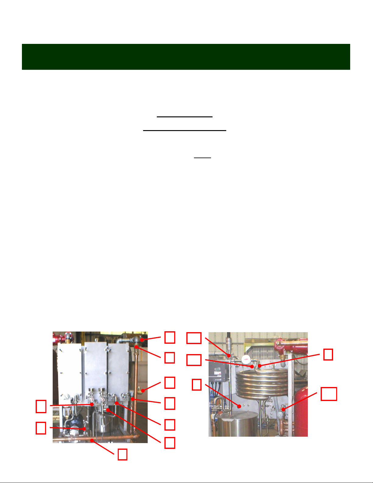
Pasteurized product outlet (standard): install a flexible hose from the
pasteurized product outlet on the back of the unit that can reach the following:
pasteurized product tank, raw product tank, and to a suitable drain. This hose
should be rated to withstand temperatures up to 190°F (87.8°C) and be chemical
resistant. At start up hose will be placed in the pasteurized product tank. When
flushing the system the hose should be directed to a drain. During cleaning, this
hose should be connected to a spray ball in the raw product tank.
Pasteurized product outlet (with cooling section): the pasteurized product
outlet is located on the front of the machine just above the balance tank. Flexible
hose or stainless tube must be run straight up from product outlet at least 2
inches (5 cm) above the plate packs to ensure that all piping fills completely.
From that point, use flexible hose as mentioned in the previous paragraph.
Pasteurized product outlet (hot-fill): the divert valve will be the product outlet
for a machine designed to hot fill product.
Filling Boiler System: to fill boiler system first make sure that all pipe fittings
are tight and the valves on the pasteurizer heating section are open. You may
decide to install a valve on the welded coupler next to the reducing valve on
the top of the 40 gallon (151.4 L) storage tank to help air removal for filling.
Open the air bleeder on top of the air scoop. Open cold water supply valve and
lift rapid fill lever, reducing valve to an upright position. Continue filling the
entire system until all air is removed and the system pressure is correct. Adjust
pressure if necessary. Place rapid fill lever back into horizontal position for
normal automatic operation and close water supply valve to prevent cold water
from entering an overheated boiler.
3-1. Installation
IMPORTANT WARNING: All electrical connections
should be made by a licensed professional in accordance
with state and local codes.

7
SECTION 3: Installation
Cooling section (optional): if your unit is equipped with a cooling section it is
the plate pack closest to the electrical enclosure.
Cold water as cooling medium: attach a cold water supply line with a valve
to the lower of the two galvanized fittings on the front of the machine. This
valve is necessary to control exiting product temperature. Run a line from the
higher fitting to drain or collect this water in a tank for other use.
Glycol chiller as cooling medium: place supply line from the chiller to the
lower of the two galvanized fittings. Place the return line to the upper fitting.
Place valves on both fittings for the purpose of servicing chiller or pasteurizer.
Please note: the flow direction of the product through the cooling section is
from top to bottom. Consequently the flow direction of the cooling medium has
to be from bottom to top.
Filler recycling valve: if you are planning on operating the pasteurizer directly
into a filler, then a filler recycling valve is recommended. Place the recycling
valve at the filler reservoir and plumb a line back to the pasteurizer's balance
tank. Connect the recycling valve to a level control in the filler reservoir. This is
so that if the reservoir becomes full the flow is directed back to the pasteurizer
to prevent from having to shut the pasteurizer off (which is not recommended).
3-1. Installation
IMPORTANT WARNING: All electrical connections
should be made by a licensed professional in accordance
with state and local codes.

8
SECTION 4: Operation
Always start machine with water. If you start the machine with product in it,
the first 10-20 gallons (38-76 L) of product will come out of the machine too hot
and fouling of the plates will occur.
Product containing large amounts of sediment has to be allowed to settle out
or be filtered before going through the pasteurizer
If your unit is equipped with a cooling section, never adjust chiller unit
temperature below 33°F (0.55°C) or freezing of the product will occur.
If while pasteurizing you experience large temperature fluctuations or unit is
diverting, adjust pump speed or adjust boiler target temperature. See
"adjusting pump speed" or "adjusting boiler temperature" sections.
Never adjust pump speed above or below the rated capacity of your machine
during pasteurization. See table below for these rates. Your machine was
factory set for the minimum and maximum. It can be operated anywhere in be-
tween those two settings.
4-1. Operation
Machine type Minimum flow Maximum flow
180 2.2 gpm (8.3 L) 3 gpm (11.4 L)
600 4.4gpm (16.7 L) 10 gpm (37.9 L)
900 8.5 gpm (32.2 L) 15 gpm (56.8 L)
1200 15 gpm (56.8 L) 20 gpm (75.7 L)

9
SECTION 4: Operation
Set-up for HTST
Dual purpose units only
1. PNP144DUAL users complete step #7 only.
2. Connect provided hose from booster pump #1 in to the raw side of the re-
generation plate pack on the back of the machine #2 in figure 1.
3. Connect provided manifold from the raw product exit of regen #8 in figure 2
to inlet of the timing pump #3 in figure 1.
4. Attach manifold from exit of regen #5 in to inlet of cooling #4.
5. Close valves labeled #1 and open valves labeled #6.
6. Open valve labeled #10.
7. Install manifold between divert valve #11 and pasteurized side of regen
#12.
8. Remove hose from between #9 in figure 2 and #3 in figure 1.
9. Finished product will exit the machine at location #9.
4-1. Operation
1
Figure 1
2
3
5
6
4
7
7
6
Figure 2
8
9
10
11
12

10
SECTION 4: Operation
Set-up for hot-fill
Dual purpose units only
1. PNP144DUAL users complete step #8 only.
2. Remove manifold going between #5 and #4.
3. Move hose from inlet of raw regen #2 to inlet of cooling #4.
4. Remove manifold from between #8 and #3.
5. Install provided 47" (119.4 cm) hose between location #9 and #3.
6. Close valve #10.
7. Close valves #6 and open valves #7.
8. Remove manifold going from divert valve #11 to regen plate pack #12. Fin-
ished product will exit the machine at location #11. Please note: you may
loosen the clamp on the divert valve and rotate it to match lines to collection
tank.
4-1. Operation
1
Figure 1
2
3
5
6
4
7
7
6
Figure 2
8
9
10
11
12

11
SECTION 4: Operation
If pasteurizer is equipped with cooling section and your cooling medium is a glycol
chiller, turn on the chiller in enough time before pasteurizing so it is at it's operating
temperature.
Fill balance tank approximately half way with water, pull out e-stop button and place
speed switch in "fast" position. Water will begin circulating through your machine. Be-
cause your machine was completely drained after factory testing you will need to add
more water as the balance tank empties to fill the entire system the first time you use
your machine.
Turn boiler power on.
Direct pasteurized product outlet hose into sanitized collection tank and open tank
valve to allow start-up water to exit tank to drain.
When unit reaches operating temperature, the divert valve will automatically close
and begin sending water through the product outlet.
Before the low level sensor shuts the pump off, press and hold the "pump override"
button to evacuate the remaining water in the tank. Do not run the pump dry.
Immediately begin introducing raw product into the balance tank. If you are pump
feeding, turn pump on or if you are gravity feeding, open raw product tank valve
make sure that the pump e-stop button is pulled out.
If your pasteurizer is equipped with a cooling section and your cooling medium is
cold water, open the supply valve to a point that results in the desired exiting product
temperature.
Place the speed switch in "slow" position if your raw product is cold or in the "fast"
position if your raw product is warm. See "adjusting pump speed" section to adjust.
Once the discharge becomes the color of product, close the valve on your collection
tank. This usually takes about 1-2 minutes.
After your raw product tank is empty, use "pump override" button to empty the last
few inches of product in the balance tank.
Immediately begin adding clean water at the raw product tank to flush the remaining
product in the system.
4-1. Operation

12
SECTION 4: Operation
Turn off chiller or close cold water supply valve to cooling section.
Once the discharge becomes cloudy, remove hose from collection tank and direct it
to drain.
Continue adding water until discharge is clear.
Shut down unit and connect outlet hose to spray ball on raw product tank.
Turn unit back on, place speed switch in "clean" position and make sure there is
enough water in both tanks to keep system running continuously.
If your unit is equipped with a pressure differential system, open the pressure relief
valve to allow maximum flow for cleaning.
Add cleaner directly into balance tank. Follow instructions on cleaner manufacturer's
label as to the amount needed.
Press and hold "divert valve" button for approximately 30 seconds to clean the line
from the valve to the balance tank.
Allow system to circulate cleaning solution for 30 minutes or longer.
When the cleaning cycle is complete, shut machine off, disconnect hose from spray ball
and direct to drain.
Pull out e-stop and run unit until low level sensor in balance tank shuts the pump off use
"pump override" button to empty remaining solution.
Add cold water at the raw product tank to flush cleaning solution from the pasteurizer.
Continue adding water until the cleaning solution has been flushed out.
Turn off machine and re-connect hose to spray ball. Turn machine back on and add
enough water to keep system running.
Add acid cleaner directly into the balance tank. Follow the label of the product you are
using to determine the amount to add.
Allow unit to circulate for approximately 10 minutes.
Press and hold "divert valve" button to clean line from valve to tank.
Shut unit off. Disconnect line from spray ball and direct to drain.
Flush acid from system in the same manner as with the cleaner.
Once acid has been flushed push e-stop button to shut machine off.
turn boiler power switch to off.
4-1. Operation

13
SECTION 4: Operation
The door of the electrical enclosure needs to be opened in order to adjust pump
speed settings. This should be done with the pasteurizer running to fine tune.
Attention: use extreme caution when working inside enclosure to avoid severe
personal injury.
To enter program mode press mode button (fig.1) on the front of the frequency drive.
This will activate the password prompt. The display will read "00" (fig. 2)
Use the arrow button to scroll to a password value of "01" then press mode.
Display will read "P01" (fig. 3) indicating the program mode has been accessed.
Use the arrow buttons to scroll to the desired parameter number. Once the desired pa-
rameter number is found, press the mode button to display current parameter setting.
P31 is for the slow speed setting
P32 is for the clean speed setting
P34 is for the fast speed setting
To adjust the current setting use the arrow buttons until desired setting is achieved.
Press the mode button to store new setting.
4-2. Adjusting Pump Speed - AC Tech Drive

14
SECTION 4: Operation
Use keypad diagram displayed below as a reference to perform the following
steps to adjust the timing pump speed.
Press the PROG/RUN button.
The password prompt will appear.
Use UP arrow key to enter a password value of "01".
Press ENTER.
Use UP arrow key to scroll to the preset speed parameters and they are as fol-
lows:
Slow/hotfill speed - preset #1 - parameter 1
Fast/htst speed - preset #4 - parameter 4
Clean speed - preset #2 - parameter 2
When desired parameter is found press enter key to shift cursor from parameter
name to parameter value.
Use UP or DOWN arrow key to adjust to desired setting.
4-2. Adjusting Pump Speed - AC Tech Drive

15
SECTION 4: Operation
The single stage controller is located on the front of the boiler behind the front
cover.
Push all three buttons at the same time (fig. 1) "PRGM" will appear and the set-
point pointer will flash (fig. 2).
Press the arrow buttons to adjust boiler setpoint temperature up or down.
Units supplied with a two stage boiler will have the temperature controller located
on the front of the boiler electrical eneclosure. The programming functions operate
in the same manner as the single stage controller.
"PRGM 1" on the two stage unit will control the high fire stage and "PRGM 2" will
control the low fire stage.
The high fire stage should always be set at least 3 degrees below the low fire
stage.
4-3. Adjusting Boiler Temperature
Fig.3
Fig.2
Fig.1

16
SECTION 4: Operation
A pressure differential system is installed on all machines with two product pumps.
This system helps maintain and monitor the pressure differential between the raw
side and pasteurized side of the regeneration plate pack. The pressure on the raw
side must always be at least 1 psi less than the pasteurized side. If the pressure on
the pasteurized side of regen drops below the raw side, the differential switch will au-
tomatically open the divert valve and send product back into the balance tank. The
system includes the following components. Refer to the photograph below to see the
item being described.
1. Raw side pressure gauge
2. Pasteurized side pressure gauge
3. Raw side pressure transducer
4. Pasteurized side pressure transducer
5. Pressure relief valve
6. Pressure differential switch (not pictured)
7. Universal timer (located inside electrical enclosure)
To adjust the pasteurized side pressure, loosen the lock nut on the relief valve (#5)
turn handle counter-clockwise to increase pressure. the raw side pressure is not ad-
justable.
4-4. Pressure Differential System
1 2
3 4
5
If your machines diverts because of
low pressure on the pasteurized
side press the divert button to reset
timer then make necessary adjust-
ment to the pressure relief valve.
Pressure differential must be set to
a minimum of 5 PSI.
Note: any time pump speed
changes exiting pressure will
change. Conversely each time
the relief valve is adjusted flow
rate will change.

17
SECTION 4: Operation
The recorder setup programming can only be accomplished when the
MODE slide switch is placed in the PROG/TEST/CAL position. This
switch is located to the left of the display. The program mode is used to
select the following: chart rotation speed, input type/ranges, display
scaling, display options, chart scaling, and relay operation.
In the program/test/calibration mode the keys will function as follows:
SCROLL when a mode or section designation is displayed, SCROLL
steps to the next mode or section.
When a parameter code is displayed, SCROLL will display the
corresponding parameter value.
When a parameter value setting is displayed, SCROLL will display the
next parameter code.
DOWN ARROW when a mode or section designation is displayed,
DOWN will enter that mode or section.
When a parameter code is displayed DOWN will display the next
parameter code.
When a parameter setting is displayed the setting will be decremented
or changed unless it is at its limit.
UP ARROW when a mode designation is displayed the UP key will
have no effect as the instrument is at the initial level.
Use the MODE switch to return to normal operation. When a section
designation is displayed the UP key will revert to the mode
designation.
When a parameter code is displayed, UP will revert back to the section
designation.
When a parameter setting is displayed, the setting will be incremented
or changed unless it is at its limit.
To enter the program/test/cal mode, position the MODE switch
accordingly. The unit will display Prog. subsequent depressions of the
SCROLL key will cause the unit to display test, and then CAL and
back to Prog.
4-5. Chart Recorder Programming

18
SECTION 4: Operation
NOTE: when the MODE switch is placed in the PROG/TEST/CAL position, all output
LEDs will be turned off and all relays will be deenergized.
To enter the program mode, press the DOWN arrow key when Prog is displayed.
The display will show PEn1 (Pen 1 parameters). Dubsequent depressions of the SCROLL
key will show PEn2 (Pen 2 parameters, if Pen 2 exists), CHAr (Chart operation), CP
(Comms parameters, if optional communications is installed) and then back to PEn1. To
enter the desired section of the program mode press the DOWN arrow key. When the desired
section is displayed use the keys as defined previously to enter modes, sections, move
around, and modify parameter settings.
The parameters and their definitions and settings can be found on the next page.
SETTING DIVERT TEMPERATURE (A1 setting)
With MODE switch in RUN position; press SCROLL key two times, this displays the setpoint
temperature at which the divert valve will close. Use the ARROW keys to adjust setpoint then
press scroll key one time to enter change.
4-5. Chart Recorder Programming
Parameter code Pen 1 Pen2
Input Selection InPS 11 for °F/10 for °C 17
Input Correction ICor 00.00
Alarm Type A1 HI N/S
Alarm Type A2 N/S N/S
Display Input/Pen Value diSP ON OFF
Decimal Point Position dPOS 00
Engineering Units (Upper) EUU N/S 5
Engineering Units (Lower) EUL N/S 0
Upper Chart Division ChUP 220 for °F/150 for °C 5
Lower Chart Division ChLO 120 for °F/50 for °C 0
Hysteresis or Switch HySt 1N/S
Display Filter Factor dFF 11
Alarm Changes ALC ON N/S
Parameter Settings

19
SECTION 4: Operation
Chart/Pen Calibration - Chrt
This cal section calibrates the pens to the chart and is divided into two additional
sections: PEn and ArC. PEn calibrates the pen spans to the chart. ArC provides a
capability to make the pens sweep the chart to facilitate mechanical adjustments of pen
arms. Pen span calibration - PEn
With Chrt in the display press DOWN to enter the chart calibration section and PEn will
be displayed. Depressing the SCROLL key will toggle between PEn and ArC. With PEn
in the display press DOWN to enter the pen span calibration section. Each pen will home
(move down-scale) and the display will blank (this could take as long as 20 seconds). The
display will show P1Lo.
With P1Lo displayed, pen 1 will be positioned at the low end of the chart. Use UP or
DOWN to position pen 1(red pen) on the inner ring of the chart. Press SCROLL when
done.
The display will now show P1Hi and the red pen will go to the outer ring of the chart. Use
UP or DOWN to adjust the pen. Press SCROLL when done.
If Pen 2 (green pen) is included, the same process must be repeated for Pen 2. After
P2Hi is completed, depressing SCROLL will return to PEn.
4-5. Chart Recorder Programming

20
SECTION 4: Operation
A-575R
A master thermometer with a high degree of accuracy should be used for calibrating. Place ther-
mometer to be calibrated alongside a master thermometer. Immerse both into an agitated liquid
for at least three minutes. Compare temperatures.
IMPORTANT: for accurate reading, thermometer must be immersed PAST GROOVE on lower
portion of stem. Master thermometer should also be immersed to the same depth. A socket
opening “RESET” is provided on bottom side of the thermometer case. Insert 1/16" (1.5 mm) hex
key into RESET opening, turn key until pointer is moved to exact temperature. Remove hex key.
To tilt thermometer head up to 90° angle, loosen screw (1) 1/2 turn only. tilt to desired angle
and tighten screw (1) as shown.
Thermometer head orientation can be adjusted ONLY when in the straight, back-connected posi-
tion. Loosen two screws (2) until harness (3) revolves freely. Hold thermometer head and har-
ness, rotate harness to desired position and tighten two screws until harness is secure. To install
thermometer into threaded connection tighten with wrench on hex nut (4) as shown..
4-6. Thermometer Calibration
This manual suits for next models
2
Table of contents
Other goodnature Industrial Equipment manuals
Popular Industrial Equipment manuals by other brands

Ohio Medical
Ohio Medical Sure-Trap Overflow Safety Trap Instructions for use

LEWCO
LEWCO 40SB owner's manual

TE Connectivity
TE Connectivity Basic AMP-O-LECTRIC K 1-471273-3 Customer's manual

Pilz
Pilz 22209-3FR-01 operating instructions

Epiroc
Epiroc 90T Safety and operating instructions

TLV
TLV DC3A-L instruction manual