manuals.online logo
Brands
  1. Home
  2. •
  3. Brands
  4. •
  5. infaco
  6. •
  7. Cutter
  8. •
  9. infaco ELECTROCOUP MEDIUM KIT F3010 User manual

infaco ELECTROCOUP MEDIUM KIT F3010 User manual

1
Notice de Montage du Kit Medium
Manual de Montaje del Kit Medium
Medium Kit Assembly Instructions
Montageanleitung des Medium-Kit
Guida per il montaggio del Kit Medium
2
3
11
2
5
8
10
9
1
7
6
4
Pour toutes ces opérations, débrancher impérativement le sécateur.
FR
ES
EN
DE
IT
Para todas estas operaciones, desconectar imperativamente la podadora.
Always disconnect the secateurs for all these operations.
Für all diese Arbeiten die Astschere unbedingt ausstecken.
Attenzione: staccare tassativamente l’alimentazione della forbice prima di
effettuare qualsiasi intervento
3
N°
Designación
1
Tornillo de cabeza avellanada M3 x 6 (x2)
2
Protege gatillo
3
Tornillo plástico de cabeza avellanada 3 x 12 (x2)
4
Brida del protege gatillo
5
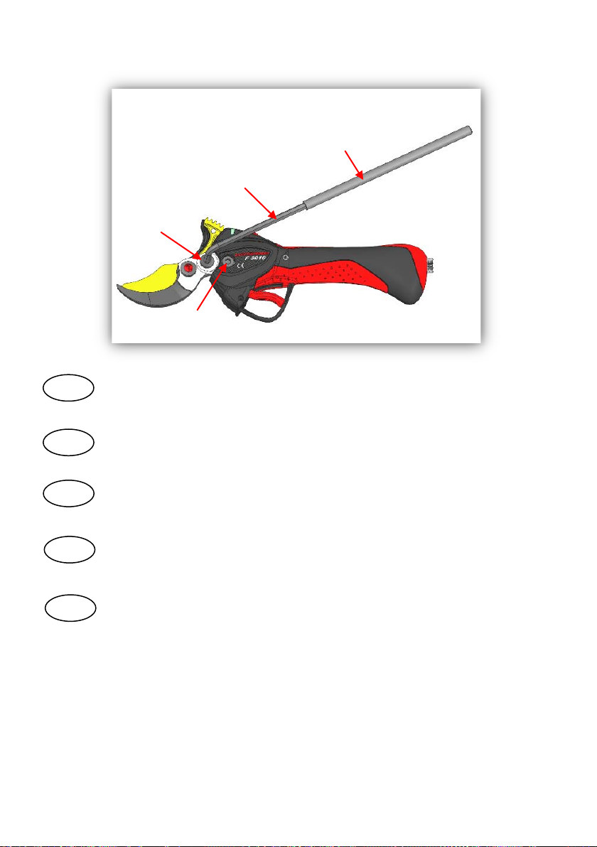
Cabeza de corte «kit Medium»
6
Tornillo hexagonal de cabeza plana M8 x 12
7
Tornillo de gancho medio
8
Tubo de pegamento
9
Alargador
10
Llave hexagonal
11
Armazón soporte Medio
N°
Désignation
1
Vis tête fraisée M3 x 6 (x2)
2
Protège doigt
3
Vis plastique tête fraisée 3 x 12 (x2)
4
Bride du protège doigt
5
Tête de coupe « kit Medium »
6
Vis CHC à tête basse M8 x 12
7
Vis crochet medium
8
Tube de colle
9
Rallonge
10
Clé 6 pans
11
Coque support Medium
No.
Designation
1 M3 x 6 countersunk screw (x2)
2
Finger guard
3 3 x 12 plastic countersunk screw (x2)
4 Finger guard flange
5 “Medium kit” cutting head
6 M8 CHC low-headed bolt x 12
7 Medium hooked bolt
8 Tube of glue
9 Extension
10 Allen key
11 Medium holder shell
N°
Bezeichnung
1 Senkschraube M3 x 6 (x2)
2
Fingerschutz
3 Kunststoff-Senkschraube 3 x 12 (x2)
4
Flansch des Fingerschutzes
5 Scherenkopf « MEDIUM-SET »
6
Flachkopfschraube mit Innensechskant,
M8 x 12
7
Schraube für Gegenschneide
medium
8
Klebstofftube
9 Verlängerung
10
Imbusschlüssel
11
Trägerschale Medium
N°
Descrizione
1 Vite testa svasata M3 x 6 (x2)
2
Para-dita
3
Vite plastica testa svasata 3 x 12 (x2)
4
Flangia para-dita
5
Testa di taglio " kit Medium”
6
Vite CHC a testa bassa M8 x 12
7 Vite gancio Medium
8
Colla
9
Prolunga
10
Chiave esagonale
11
Piastra supporto Medium
Vidéo du montage disponible sur
le site internet : www.infaco.com
IT
FR
ES
EN
DE
IT
Composition du Kit Medium
ES
EN
DE
FR
Composición del Kit Medium
Video del montaje disponible en la
página:
www.infaco.com
Composition of the Medium Kit
Assembly video available on the
website: www.infaco.com
Zusammensetzung des Medium-
Kit
Videofilm der Montage verfügbar in
der Internetsite: www.infaco.com
Composizione del Kit
Medium
È possibile scaricare un breve video
dal sito internet: www.infaco.com
4
12
13
Retirer les deux vis n°12 du capot.
FR
ES
EN
DE
IT
Retirer le capot n°13.
FR
ES
EN
DE
IT
Démontage de la tête de coupe
FR
Penser à bien conserver toutes les pièces.
FR
ES
EN
DE
IT
ES
Desmontaje de la cabeza de corte
Acuérdese de conservar todas las piezas.
Retirar los dos tornillos nº 12 de la tapa.
Retirar la tapa nº 13.
EN
Dismantling the cutting head
Make sure you keep all the parts.
Remove the two screws no. 12 from the
hood.
Remove hood no. 13.
DE
Demontage des Scherenkopfs
Denken Sie daran, alle Teile aufzubewahren.
Die zwei Schrauben (Nr. 12) von der
Abdeckung nehmen.
Die Abdeckung (Nr. 13) abnehmen.
IT
Smontaggio della testa di taglio
Rimuovere le due viti 12 del coperchio.
Rimuovere il coperchio 13
Attenzione a riporre bene i singoli elementi
onde non prederli
5
14
15
FR
Retirer la vis de blocage n°14 et la
rondelle plastique n°15.
ES
EN
DE
IT
Retirer l’écrou de lame n°16.
FR
ES
EN
DE
IT
16
Retirer l’ensemble crémaillère n°17, lame
n°18 et rondelle n°19. Si nécessaire,
nettoyer le pourtour du pignon.
FR
17
19
18
ES
EN
DE
IT
Retirar el tornillo de tope nº14 y la
arandela plástica n°15.
Retirar la tuerca de la hoja n°16.
Retirar el conjunto cremallera nº17, hoja
nº18 y arandela nº19. Si necesario, limpiar
el contorno del piñón.
Remove locking bolt no. 14 and plastic
washer no. 15.
Remove blade screw no. 16.
Remove rack mechanism no. 17, blade no. 18
and washer no.19. Clean around the pinion if
necessary.
Die Mutter des Schneidmessers (Nr. 16)
abnehmen.
Rimuovere la vite di bloccaggio 14 e la
rondella di plastica 15.
Rimuovere il dado della lama 16.
Rimuovere l’insieme cremagliera 17,la lama
18 e la rondella 19. Se necessario, pulire il
perimetro del pignone.
Die Konterschraube (Nr. 14) und die
Kunststoff U-Scheibe (Nr. 15) abnehmen.
Das Zahnrad (Nr.17), das Schneidmesser
(Nr.18) und die U-Scheibe (Nr.19) abnehmen.
Bei Bedarf das Ritzel reinigen.
6
FR
Retirer le bouchon de graissage n°20.
ES
EN
DE
IT
FR
20
10
9
21
23
22
ES
EN
DE
IT
A l’aide de la clé n°9 et de la rallonge n°10, retirer l’axe de lame n°21 et la vis n°23. Puis
retirer le crochet n°22.
Attention : serrer modérément l’étau.
Retirar el tapón de engrasado nº20.
Con ayuda de la llave nº9 y del alargador nº10, retirar el eje de la hoja nº21 y el tornillo
nº23. Después retirar el gancho nº22.
Atención: Apretar ligeramente el tornillo.
Remove greasing bung no. 20.
Using Allen key no. 9 and extension no. 10, remove blade axis no. 21 and bolt no. 23.
Then remove hook no. 22.
N.B. tighten the vice only moderately.
Rimuovere il tappo di lubrificazione 20.
Den Schmiernippel (Nr. 20) entfernen.
Mit Hilfe des Schlüssels (Nr. 9) und der Verlängerung (Nr. 10) die Achse des Schneidmessers
(Nr. 21) und die Schraube (Nr. 23) abnehmen. Dann die Gegenschneide (Nr. 22) abnehmen.
Achtung: Die Spannvorrichtung mäßig anziehen.
Usare la chiave 9 e la leva 10 per estrarre il perno della lama 21 e la vite 23. A questo
punto, smontare il gancio 22.
Attenzione a non stringere troppo le morse.
7
FR
Montage du Kit Medium
ES
EN
DE
IT
Visser les deux vis (M3 x 6) n°1.
FR
1
3 2
Positionner le protège doigt n°2 et bloquer à
l’aide de la vis plastique (3 x 12) n°3.
FR
ES
EN
DE
IT
ES
EN
DE
IT
Montaje del Kit Medium
Atornillar los dos tornillos (M3 x 6) n°1.
Posicionar el protege gatillo nº2 y bloquear
con ayuda del tornillo de plástico (3 x 12) n°3.
Assembling the Medium Kit
Screw in the two screws (M3 x 6) no. 1.
Position finger guard no. 2 and lock in place
using plastic screw (3 x 12) no. 3.
Montage des Medium-Kit
Die zwei Schrauben (M3 x 6) (Nr. 1)
anziehen.
Montaggio del Kit Medium
Avvitare le due viti 1 (M3 x 6).
Den Fingerschutz (Nr.2) positionieren und
mit der Kunststoffschraube(3 x 12) (Nr. 3)
anziehen.
Posizionare il pars-dita 2 e bloccarlo con la
vite di plastica 3 (3 x 12).
8
3
4
FR
Positionner la bride n°4 sur le protège doigt
et bloquer à l’aide de la vis plastique (3 x 12)
n°3.
ES
EN
DE
IT
FR
Graisser avec de la graisse universelle la denture de la crémaillère et du pignon. Puis
positionner la tête de coupe Medium n°5 sur la tête du sécateur.
5
ES
EN
DE
IT
Posicionar la brida nº4 sobre el protege
gatillo y bloquear con la ayuda del tornillo de
plástico (3 x 12) n°3.
Engrasar con grasa universal el engranaje de la cremallera y el piñón. Posicionar la
cabeza de corte Medium nº5 sobre la cabeza de la podadora.
Position flange no. 4 on the finger guard
and lock in place using plastic screw (3 x
12) no. 3.
Grease the cogs on the rack and pinion mechanism with universal grease. Then position
Medium cutting head no. 5 on the head of the secateurs.
Mit dem Universalfett die Zahnung des Zahnrads und das Ritzels schmieren. Dann den
Medium Scherenkopf (Nr. 5) am Kopf der Astschere positionieren.
Den Flansch (Nr.4) am Fingerschutz
positionieren und mit der Schraube (3 x 12)
(Nr.3) anziehen.
Posizionare la flangia 4 sul para-dita e
bloccarlo con la vite di plastica 3 (3 x 12).
Lubrificare con grasso universale la dentatura della cremagliera e del pignone prima di
montare la testa di taglio Medium 5 sulla testa delle forbici.
9
7
6
8
FR
Visser les vis n°6 et n°7 au crochet.
ES
EN
DE
IT
7
6
FR
A l’aide du tube de colle n°8, imprégner UNIQUEMENTles filets de la vis n°6 en
retirant le surplus de colle.
Attention : Ne pas encoller la vis n°7
ES
EN
DE
IT
Con ayuda del tubo de cola nº8, impregnar ÚNICAMENTE las roscas de los tornillos
nº6 y retirar el exceso de cola.
Atención: No pegar el tornillo nº7
Atornillar el tornillo nº6 y nº7 al gancho.
Use the tube of glue no. 8 to fill ONLY the thread of bolt no. 6 with glue. Remove any
surplus.
N.B. Do not put glue on bolt no. 7
Screw bolt nos. 6 and 7 to the hook.
Mit der Klebstofftube (Nr.8) NUR das Gewinde der Schraube (Nr. 6) benetzen.
Überflüssigen Klebstoff bitte entfernen.
Achtung: Die Schraube (Nr. 7) nicht mit Klebstoff versehen.
Die Schrauben (Nr. 6 und 7) an die
Gegenklinge montieren.
Usare la colla 8 badando a spalmarla SOLO sul filetto della vite 6 e pulendo eventuale
eccesso di colla.
Attenzione: Non incollare la vite 7
Stringere le viti 6 e 7 sul gancio.
10
10
9
FR
ES
EN
DE
IT
7
6
A l’aide de la clé n°10 et de la rallonge n°9, bloquer la vis n°7 (fort serrage) et la vis n°6
(serrage normal).
(Avec une clé dynamométrique, bloquer la vis n°7 à 50N.m et la vis n°6 à 30N.m).
Con ayuda de la llave nº10 y del alargador nº9, bloquear el tornillo nº7 (apretar fuerte) y el
tornillo nº6 (apretar normal).
(Con una llave dinamométrica, bloquear el tornillo nº7 a 50N.m y el tornillo nº6 a 30N.m).
Use Allen key no. 10 and extension no. 9 to lock bolt no. 7 (tighten firmly) and bolt
no. 6 (tighten normally).
(Use a torque wrench to lock bolt no. 7 at 50N.m and bolt no. 6 at 30N.m).
Mit dem Schlüssel (Nr. 10) und der Verlängerung (Nr. 9) die Schraube (Nr. 7) (stark) und die
Schraube (Nr. 6) (normal) anziehen).
(Mit einem Drehmomentschlüssel die Schraube (Nr. 7) mit 50N.m und die Schraube (Nr. 6)
mit 30N.m anziehen.)
Usare la chiave 10 e la leva 9 per bloccare la vite 7 (serraggio forte) e la vite 6 (serraggio
normale). Usare una chiave dinamometrica per stringere la vite 7 a 50Nm e la vite 6 a
30Nm.
11
24
25
11
FR
Changement de coque du support sécateur
ES
EN
DE
IT
FR
Retirer la coque n°25 du support sécateur n°24 en pressant sur le plot n°26.
Puis, clipper la coque n°11 fournis dans le kit.
ES
EN
DE
IT
26
Cambio del armazón de soporte de la podadora
Changing the holder shell
Remove shell no. 25 from secateurs holder no. 24 by pressing socket no. 26.
Then clip on shell no. 11 supplied with the kit.
Auswechseln der Trägerschale der Astschere
Retirar el armazón nº25 del soporte de la podadora nº24 presionando el botón nº26.
Enganchar el soporte nº11 suministrado con el kit.
Die Schale (Nr. 25) vom Träger der Astschere (Nr. 24) abnehmen, indem auf den Knopf
(Nr. 26) gedrückt wird. Dann die im Lieferumfang des Sets enthaltene Schale (Nr. 11) an
klipsen.
Cambio della piastra di supporto
Rimuovere la piastra 25 del supporto 24 premendo sulla linguetta 26 prima di
incastrare la piastra 11 in dotazione nel kit.
12
FR
Procédure Electronique de mise en route du Kit
ES
EN
DE
IT
29
28
27
30
FR
Brancher la prise n°27 de la batterie à la prise n°28 du boitier de commande. Brancher
la prise n°29 du câble spiralé à la prise n°30 du sécateur.
ES
EN
DE
IT
Procedimiento Electrónico de puesta en marcha del Kit
Conectar la toma nº27 de la batería a la toma nº28 de la caja de mandos. Conectar la
toma nº29 del cable en espiral a la toma nº30 de la podadora.
Electronic procedure for starting up the Kit
Connect battery socket no. 27 to control box socket no. 28. Connect spiral cable socket
no. 29 to secateurs socket no. 30.
Inbetriebnahme von Medium Kit
Den Stecker (Nr. 27) des Akkus an den Stecker (Nr. 28) die Steuerbox anschließen. Den
Stecker des Spiralkabels (Nr. 29) an die Buchse (Nr. 30) der Astschere anschließen.
Procedura elettronica di accensione Kit
Collegare la spina 27 della batteria alla presa 28 della scatola di comando. Collegare la
presa 29 del cavo spiralato alla spina 30 delle forbici.
13
FR
Réarmer l’interrupteur n°31 « ON/OFF » du
boitier de commande. s’affiche.
31
32
ES
EN
DE
IT
P01
BLADE
FR
Appuyer 5 secondes sur le bouton n°32 jusqu'à ce que « P01 BLADE » s’affiche.
Ensuite, appuyer encore 3 secondes sur le bouton n°32 pour entrer dans le
programme. «P01 BLADE » clignote.
ES
EN
DE
IT
32
Rearmar el interruptor nº31 «ON/OFF» de la
caja de mandos. Se visualiza .
Pulsar 5 segundos el botón nº32 hasta que se visualiza « P01 BLADE ». A
continuación, pulsar 3 segundos sobre el botón nº32 para entrar en el programa.
«P01 BLADE » parpadea.
Reset control box “ON/OFF”switch no. 31.
is displayed.
Press button no. 32 for 5 seconds until “P01 BLADE” is displayed. Then press button
no. 32 for another 3 seconds to enter the program. “P01 BLADE” flashes.
5 Sekunden lang auf die Taste (Nr. 32) drücken, bis « P01 BLADE » angezeigt wird.
Dann nochmals 3 Sekunden auf die Taste (Nr. 32) drücken, um in das Programm zu
gehen. «P01 BLADE » blinkt.
Reset des Schalters (Nr. 31) « EIN/AUS » An
der Steuerbox wird angezeigt.
Premere 5 secondi il bottone 32 fino a visualizzare "P01 BLADE”. Poi ripremere il
bottone 32 per altri 3 secondi per entrare nel programma. A questo punto la scritta
“
P01 BLADE"
lampeggia.
Riarmare l’interruttore 31 "ON/OFF" della
scatola di comando e attendere che
compaia
14
FR
Démarrer le sécateur en actionnant 2 fois la
gâchette n°33.
ES
EN
DE
IT
33
FR
Actionner la gâchette n°33 jusqu'à la fermeture complète de la lame, puis actionner
par brève impulsion la gâchette n°33 pour obtenir la position de lame souhaitée.
ES
EN
DE
IT
33
Activar la podadora accionando 2 veces el
gatillo nº33.
Accionar el gatillo nº33 hasta el cierre completo de la hoja, a continuación
accionar mediante una pulsación breve el gatillo nº33 para obtener la posición de
la hoja deseada.
Start the secateurs by pressing trigger no. 33
twice.
Press trigger no. 33 until the blade closes completely, then press trigger no. 33 in
short movements to obtain the required blade position.
Die Astschere starten indem 2 Mal auf den
Bedienungsschalter (Nr. 33) gedrückt wird.
Den Bedienungsschalter (Nr. 33) betätigen, bis sich das Schneidmesser komplett
schließt, dann durch kurzes Drücken den Bedienungsschalter (Nr. 33) betätigen, um
die gewünschte Position des Schneidmessers zu erhalten.
Avviare le forbici azionando due volte il
grilletto 33.
Azionare il grilletto 33 fino alla chiusura completa della lama, poi dare un altro piccolo
impulso al grilletto 33 per portare la lama nella posizione voluta.
15
FR
Sans relâcher la gâchette n°33, valider la position de la lame en appuyant 3
secondes sur le bouton n°32 du boitier de commande. « P01 BLADE OK » s’affiche.
ES
EN
DE
IT
P01 OK
BLADE
3233
33
Démarrer le sécateur en actionnant 2 fois la gâchette n°33. Vérifier le fonctionnement
du sécateur en réalisant quelques coupes. Si le sécateur ne fonctionne pas
correctement, recommencer la procédure de mise en route.
FR
ES
EN
DE
IT
Sin soltar el gatillo nº33, validar la posición de la hoja presionando 3 segundos el
botón nº32 de la caja de mandos. Se visualiza « P01 BLADE OK ».
Activar la podadora accionando 2 veces el gatillo nº33. Comprobar el funcionamiento
de la podadora realizando varios cortes. Si la podadora no funciona correctamente
realizar de nuevo el procedimiento de puesta en marcha.
Without releasing trigger no. 33, confirm the blade position by pressing button no. 32
on the control box for 3 seconds. “P01 BLADE OK” is displayed.
Start the secateurs by pressing trigger no. 33 twice. Try a few cuts to check that the
secateurs are working correctly. If they are not working correctly, go through the start-
up procedure again.
Ohne den Bedienungsschalter (Nr.33) loszulassen, die Position des Schneidmessers
bestätigen, indem 3 Sekunden lang auf die Taste (Nr.3 2) des Steuerblocks gedrückt
wird. « P01 BLADE OK » wird angezeigt.
Die Astschere starten, indem 2 Mal auf den Bedienungsschalter (Nr. 33) gedrückt wird. Den
Betrieb der Astschere überprüfen, indem einige Schnitte gemacht werden. Funktioniert die
Astschere nicht korrekt, das Verfahren der Inbetriebnahme nochmals wiederholen.
Senza mai rilasciare il grilletto 33, confermare la posizione della lama premendo il
pulsante 32 della scatola di comando per 3 secondi ed attendere che venga
visualizzata la scritta “P01 BLADE OK".
Avviare le forbici azionando 2 volte il grilletto 33. Verificate il funzionamento delle forbici
effettuando alcuni tagli. Se le forbici non funzionano correttamente, ripetere la
procedura di accensione.
(FR) Constructeur : INFACO S.A.S. - 81140 CAHUZAC-SUR-VÈRE (FRANCE)
(ES) Fabricante: INFACO S.A.S. - 81140 CAHUZAC-SUR-VÈRE (FRANCIA)
(EN) Manufacturer : INFACO S.A.S. - 81140 CAHUZAC-SUR-VÈRE (FRANCE)
(DE) Hersteller : INFACO S.A.S. - 81140 CAHUZAC-SUR-VÈRE (FRANKREICH)
(IT) Costruttore : INFACO S.A.S. - 81140 CAHUZAC-SUR-VÈRE (FRANCIA)
(FR) Type: KIT MEDIUM F3010
(ES) Tipo: KIT MEDIUM F3010
(EN) Type: MEDIUM KIT F3010
(DE) Art: MEDIUM-SET F3010
(IT) Tipo: KIT MEDIUM F3010
INFACO S.A.S.
Bois de Roziès
81140 CAHUZAC-SUR-VÈRE (FRANCE)
Tél. : (+33) 05 63 33 91 49 - Fax : (+33) 05 63 33 95 57
E-mail : electrocoup@infaco.fr
(FR) MATERIEL FABRIQUE EN FRANCE
(ES) MATERIAL FABRICADO EN FRANCIA
(EN) EQUIPMENT MADE IN FRANCE
(DE) MATERIAL IN FRANKREICH HERGESTELLT
(IT) MATERIALE FABBRICATO IN FRANCIA

This manual suits for next models

1

Popular Cutter manuals by other brands

Huskie Tools S-16 Operating instructions manual

Huskie Tools

Huskie Tools S-16 Operating instructions manual

EINHELL 43.013.20 operating instructions

EINHELL

EINHELL 43.013.20 operating instructions

Enerpac EBC20B instruction sheet

Enerpac

Enerpac EBC20B instruction sheet

Carlisle Binkes 201-510 Service manual

Carlisle

Carlisle Binkes 201-510 Service manual

Hitachi CM 4ST Technical data and service manual

Hitachi

Hitachi CM 4ST Technical data and service manual

LOBSTER EH-19PCU Owner's manual & operating instructions

LOBSTER

LOBSTER EH-19PCU Owner's manual & operating instructions

D-CUT HC-040 Operation manual

D-CUT

D-CUT HC-040 Operation manual

Holmatro HCT5111 Series manual

Holmatro

Holmatro HCT5111 Series manual

Thermal Dynamics A80 CUTMASTER operating manual

Thermal Dynamics

Thermal Dynamics A80 CUTMASTER operating manual

Schiller Classen HSC18HD manual

Schiller

Schiller Classen HSC18HD manual

KLIC-N-KUT KNK Force user manual

KLIC-N-KUT

KLIC-N-KUT KNK Force user manual

Uniflex EM 1 operating manual

Uniflex

Uniflex EM 1 operating manual

ADE VITALIS Series operating manual

ADE

ADE VITALIS Series operating manual

Makita CC301D instruction manual

Makita

Makita CC301D instruction manual

RotaTrim PT Series Operator's manual

RotaTrim

RotaTrim PT Series Operator's manual

Milwaukee C12 PPC-0 PEX Original instructions

Milwaukee

Milwaukee C12 PPC-0 PEX Original instructions

Makita CC300D instruction manual

Makita

Makita CC300D instruction manual

Land Pride RCR2660 Operator's manual

Land Pride

Land Pride RCR2660 Operator's manual

manuals.online logo
manuals.online logoBrands
  • About & Mission
  • Contact us
  • Privacy Policy
  • Terms and Conditions

Copyright 2025 Manuals.Online. All Rights Reserved.