Inficon BPG400 User manual
Operating Manual
tina03e1 (0206) 1
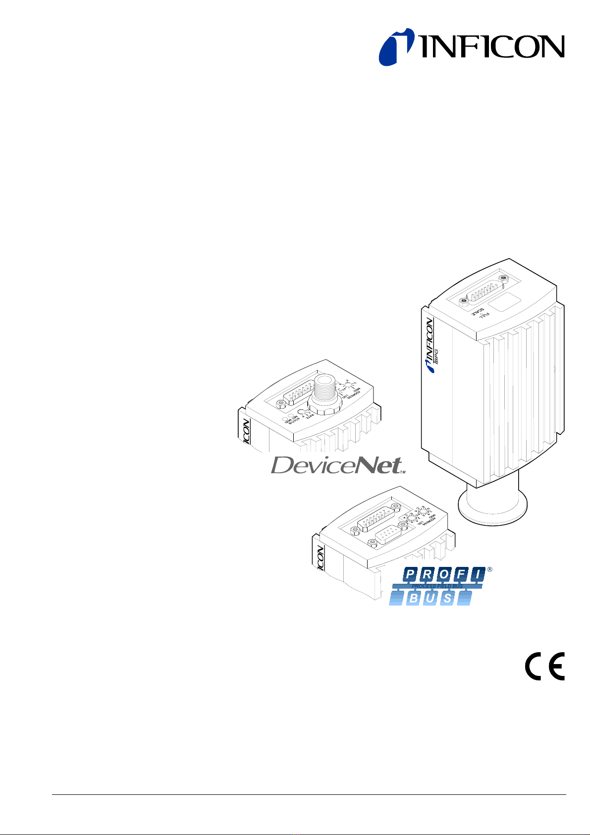
Bayard-Alpert Pirani Gauge
BPG400
BPG400-SD
BPG400-SP
2tina03e1 (0206) BPG400 v1.om
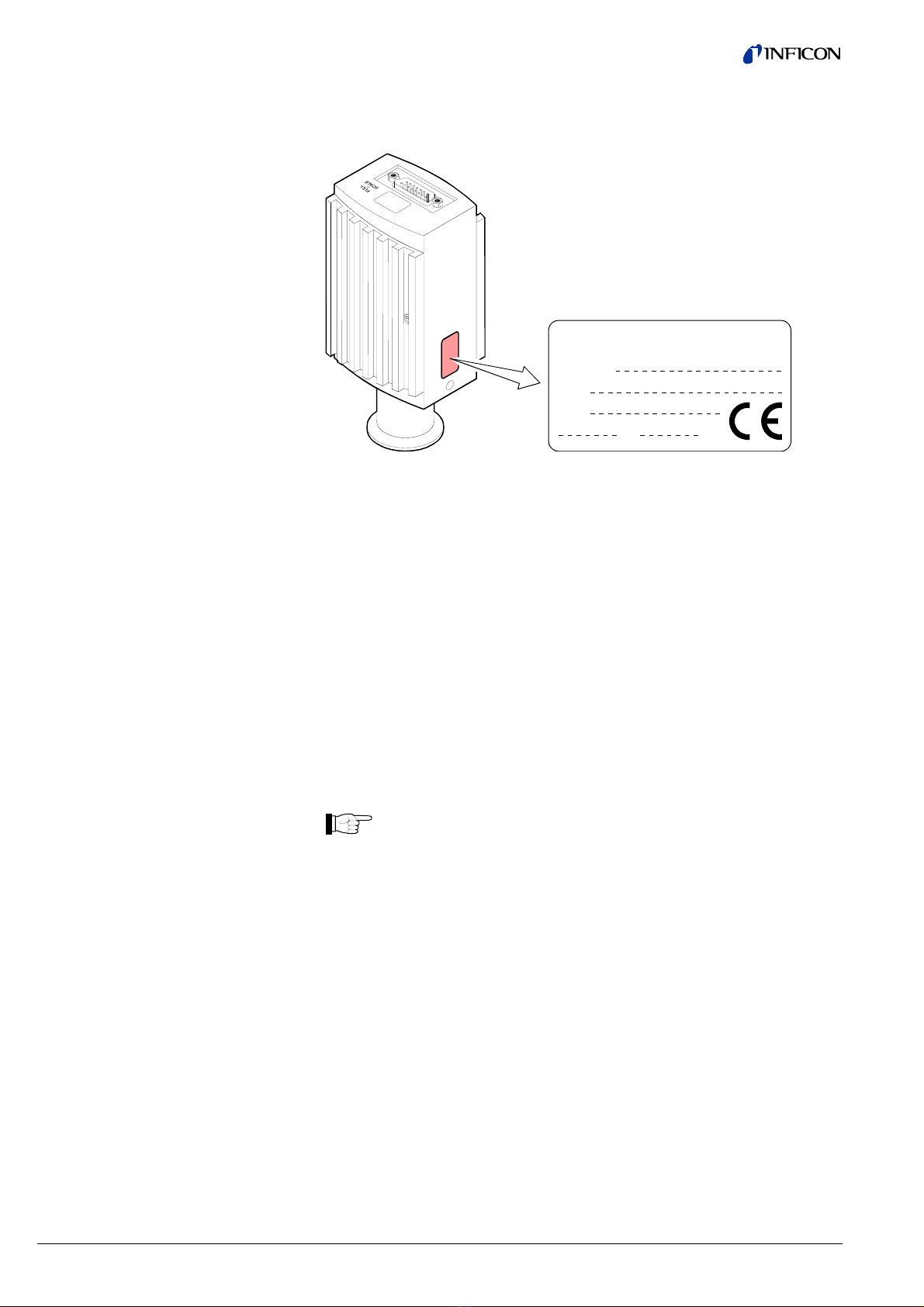
In all communications with INFICON, please specify the information on the product
nameplate. For convenient reference copy that information into the space provided
below.
Model:
PN:
SN:
V W
INFICON AG, LI-9496 Balzers
This document applies to products with the following part numbers:
BPG400 (without display)
353-500 (vacuum connection DN 25 ISO-KF)
353-502 (vacuum connection DN 40 CF-R)
BPG400 (with display)
353-501 (vacuum connection DN 25 ISO-KF)
353-503 (vacuum connection DN 40 CF-R)
BPG400-SD (with DeviceNet interface and switching functions)
353-507 (vacuum connection DN 25 ISO-KF)
353-508 (vacuum connection DN 40 CF-R)
BPG400-SP (with Profibus interface and switching functions)
353-505 (vacuum connection DN 25 ISO-KF)
353-506 (vacuum connection DN 40 CF-R)
The part number (PN) can be taken from the product nameplate.
If not indicated otherwise in the legends, the illustrations in this docu-
ment correspond to the KF vacuum connection. They apply to other
vacuum connections by analogy.
In illustrations that apply to all types of the BPG400 gauge family, the
gauge with part number 353-500 is shown.
All BPG400 versions are shipped with an instruction sheet (®&[8]). BPG400-SD
and BPG400-SP come with a supplementary instruction sheet describing the field-
bus interfaces and the switching functions (®&[9]).
We reserve the right to make technical changes without prior notice.
The BPG400 gauges have been designed for vacuum measurement of non-flam-
mable gases and gas mixtures in a pressure range of 5×10⁻¹⁰ … 1000 mbar.
The gauges can be operated in connection with the INFICON Vacuum Gauge
Controller VGC103 or VGC40x or with other control devices.
Product Identification
Validity
Intended Use

tina03e1 (0206) BPG400 v1.om 3
Over the whole measuring range, the gauge has a continuous characteristic curve
and its measuring signal is output as logarithm of the pressure.
The gauge functions with a Bayard-Alpert hot cathode ionization measurement
system (for p < 2.0×10⁻² mbar) and a Pirani measurement system (for
p > 5.5×10⁻³ mbar). In the overlapping pressure range of 2.0×10⁻² …
5.5×10⁻³ mbar, a mixed signal of the two measurement systems is output. The hot
cathode is switched on by the Pirani measurement system only below the switching
threshold of 2.4×10⁻² mbar (to prevent filament burn-out). It is switched off when the
pressure exceeds 3.2×10⁻² mbar.
DeviceNet™ Open DeviceNet Vendor Association, Inc.
Functional Principle
Trademarks

4tina03e1 (0206) BPG400 v1.om
Contents
Product Identification 2
Validity 2
Intended Use 2
Functional Principle 3
Trademarks 3
1 Safety 6
1.1 Symbols Used 6
1.2 Personnel Qualifications 6
1.3 General Safety Instructions 7
1.4 Liability and Warranty 7
2 Technical Data 8
3 Installation 13
3.1 Vacuum Connection 13
3.1.1 Removing and Installing the Electronics Unit 15
3.1.2 Installing the Optional Extension 16
3.1.3 Using the Optional Baffle 17
3.1.3.1 Installing the Baffle 17
3.1.3.2 Replacing the Baffle 19
3.2 Electrical Connection 20
3.2.1 Use With INFICON VGC103 or VGC40x Vacuum Gauge Controller 20
3.2.2 Use With Other Controllers 21
3.2.2.1 Making an Individual Sensor Cable 21
3.2.2.2 Making a DeviceNet Interface Cable (BPG400-SD) 24
3.2.2.3 Making a Profibus Interface Cable (BPG400-SP) 25
3.2.3 Using the Optional Power Supply (With RS232C Line) 26
4 Operation 28
4.1 Measuring Principle, Measuring Behavior 28
4.2 Operational Principle of the Gauge 29
4.3 Putting the Gauge Into Operation 29
4.4 Degas 30
4.5 Display (BPG400) 30
4.6 RS232C Interface 32
4.6.1 Description of the Functions 32
4.6.1.1 Output String (Transmit) 32
4.6.1.2 Input String (Receive) 34
4.7 DeviceNet Interface (BPG400-SD) 35
4.7.1 Description of the Functions 35
4.7.2 Operating Parameters 35
4.7.2.1 Operating Software 35
4.7.2.2 Node Address Setting 35
4.7.2.3 Data Rate Setting 36
4.7.3 Status Lights 36
4.8 Profibus Interface (BPG400-SP) 37
4.8.1 Description of the Functions 37
4.8.2 Operating Parameters 37
4.8.2.1 Operating Software 37
4.8.2.2 Node Address Setting 37
4.9 Switching Functions (BPG400-SD, BPG400-SP) 38
4.9.1 Setting the Switching Functions 38
5 Deinstallation 40

tina03e1 (0206) BPG400 v1.om 5
6 Maintenance, Repair 42
6.1 Maintenance 42
6.1.1 Cleaning the Gauge 42
6.2 Adjusting the Gauge 42
6.2.1 Adjustment at Atmospheric Pressure 42
6.2.2 Zero Point Adjustment 43
6.3 What to Do in Case of Problems 44
6.4 Replacing the Sensor 46
7 Options 47
8 Spare Parts 47
9 Storage 47
10 Returning the Product 48
11 Disposal 48
Appendix 49
A: Relationship Output Signal – Pressure 49
B: Gas Type Dependence 50
C: Literature 52
Declaration of Contamination 53
For cross-references within this document, the symbol (®2XY) is used, for cross-
references to further documents and data sources, the symbol (®&[Z]).

6tina03e1 (0206) BPG400 v1.om
1 Safety
DANGER
Information on preventing any kind of physical injury.
WARNING
Information on preventing extensive equipment and environmental damage.
Caution
Information on correct handling or use. Disregard can lead to malfunctions or
minor equipment damage.
Notice
Hint, recommendation
The result is O.K.
The result is not as expected
Optical inspection
Waiting time, reaction time
Skilled personnel
All work described in this document may only be carried out by persons who
have suitable technical training and the necessary experience or who have been
instructed by the end-user of the product.
1.1 Symbols Used
1.2 Personnel Qualifications

tina03e1 (0206) BPG400 v1.om 7
· Adhere to the applicable regulations and take the necessary precautions for the
process media used.
Consider possible reactions between the materials (®211) and the process
media.
Consider possible reactions of the process media due to the heat generated by
the product.
· Adhere to the applicable regulations and take the necessary precautions for all
work you are going to do and consider the safety instructions in this document.
· Before beginning to work, find out whether any vacuum components are con-
taminated. Adhere to the relevant regulations and take the necessary precau-
tions when handling contaminated parts.
Communicate the safety instructions to all other users.
INFICON assumes no liability and the warranty becomes null and void if the end-
user or third parties
· disregard the information in this document
· use the product in a non-conforming manner
· make any kind of interventions (modifications, alterations etc.) on the product
· use the product with accessories not listed in the corresponding product
documentation.
The end-user assumes the responsibility in conjunction with the process media
used.
1.3 General Safety
Instructions
1.4 Liability and Warranty
8tina03e1 (0206) BPG400 v1.om
2 Technical Data
Measuring range (air, N2, O2) 5×10⁻¹⁰ … 1000 mbar, continuous
Accuracy 15% of reading in the range of
10-8 … 10-2 mbar
(after 5 min stabilization)
Repeatability 5% of reading in the range of
10-8 … 10-2 mbar
(after 5 min stabilization)
Gas type dependence ®Appendix B
Switching on threshold
Switching off threshold
2.4×10⁻² mbar
3.2×10⁻² mbar
Emission current
p £7.2×10⁻⁶ mbar
7.2×10⁻⁶ mbar <p <3.2×10⁻² mbar
5 mA
25 µA
Emission current switching
25 µA Þ5 mA
5 mA Þ25 µA
7.2×10⁻⁶ mbar
3.2×10⁻⁵ mbar
Degas emission current
(p <7.2×10⁻⁶ mbar)
»16 mA (Pdegas »4 W)
Control input signal 0 V/+24 VDC, active high
(control via RS232 ®232)
Duration max. 3 min, followed by automatic stop
In degas mode, BPG400 gauges keep supplying measurement values, however
their tolerances may be higher than during normal operation.
Output signal (measuring signal) 0 … +10 V
Measuring range 0.774 V Z5×10-10 mbar
… +10 V Z1000 mbar
Relationship voltage-pressure logarithmic, 0.75 V/decade
(®Appendix A)
Error signal <0.3 V/0.5 V (®244)
Minimum loaded impedance 10 kW
Display panel
Dimensions
Pressure units (pressure p)
LCD matrix, 32×16 pixels,
with background illumination
16.0 mm × 11.2 mm
mbar (default), Torr, Pa
(selecting the pressure unit ®232)
DANGER
The gauge must only be connected to power supplies, instruments or
control devices that conform to the requirements of a grounded extra-
low voltage (SELV-E according to EN 61010). The connection to the
gauge has to be fused (INFICON-controllers fulfill these requirements).
Measurement
Emission
Degas
Output signal
Display (BPG400)
Power supply

tina03e1 (0206) BPG400 v1.om 9
Operating voltage at the gauge +24 VDC (20 … 28 VDC) 1)
ripple max. 2 Vpp
Power consumption
Standard
Degas
Emission start (<200 ms)
£0.5 A
£0.8 A
£1.4 A
Power consumption
BPG400
BPG400-SD, BPG400-SP
£16 W
£18 W
Fuse necessary 1.25 AT
BPG400-SD requires an additional, separate power supply for the
DeviceNet interface (®224).
Supply voltage at the DeviceNet con-
nector, (Pin 2 and Pin 3) +24 VDC (+11 … 25 VDC)
Power consumption <2 W
The gauge is protected against reversed polarity of the supply voltage.
For reasons of compatibility, the expression "sensor cable" is used for all
BPG400 versions in this document, although the pressure reading of the
gauges with fieldbus interface (BPG400-SD and BPG400-SP) is
normally transmitted via DeviceNet or Profibus.
Electrical connector
BPG400
BPG400-SD, BPG400-SP
D-Sub,15 pins, male
®222
®223
Cable for BPG400
Analog values only
Without degas function
Analog values
With degas function
Analog values
With degas function
And RS232C interface
Cable for BPG400-SD, BPG400-SP
4 conductors plus shielding
5 conductors plus shielding
7 conductors plus shielding
depending on the functions used,
max. 15 conductors plus shielding
Max. cable length (supply voltage 24 V1))
Analog and fieldbus operation
RS232C operation
£35 m, conductor cross-section 0.25 mm²
£50 m, conductor cross-section 0.34 mm²
£100 m, conductor cross-section 1.0 mm²
£30 m
Gauge identification 42 kWresistor between Pin 10 (sensor
cable) and GND
Switching functions
BPG400
BPG400-SD, BPG400-SP
Adjustment range
none
2 (Setpoints A and B)
1×10⁻⁹ mbar … 100 mbar
Setpoints adjustable via potentiometers
(Setpoints A and B), one floating, nor-
mally open relay contact per setpoint
(®223, 38)
Relay contact rating
Voltage
Current
£60 V
£0.5 ADC
1) Measured at sensor cable connector (consider the voltage drop as function of
the sensor cable length).
Sensor cable

10 tina03e1 (0206) BPG400 v1.om
Data rate
Data format
Connections (sensor cable connector)
TxD (Transmit Data)
RxD (Receive Data)
GND
9600 baud
binary
8 data bits
one stop bit
no parity bit
no handshake
Pin 13
Pin 14
Pin 5
(Function and communication protocol of the RS232C interface ®232)
Fieldbus name DeviceNet
Standard applied ®&[6]
Communication protocol, data format ®&[1], [4]
Interface, physical CAN bus
Data rate (adjustable via "RATE"
switch)
125 kbaud
250 kbaud
500 kbaud
"P" (125 kbaud, 250 kbaud, 500 kbaud
programmable via DeviceNet
(®&[1])
Node address (MAC ID)
(Adjustable via "ADDRESS", "MSD",
"LSD" switches)
0 … 63dec
"P" (0 … 63 programmable via
DeviceNet, ®&[1])
DeviceNet connector Micro-Style, 5 pins, male
Cable Shielded, special DeviceNet cable,
5 conductors (®224 and &[4])
Cable length, system wiring According to DeviceNet specifications
(®&[6], [4])
Fieldbus name Profibus
Standard applied ®&[7]
Communication protocol data format ®&[10], [7]
Interface, physical RS485
Data rate £12 Mbaud (®&[10])
Node address
(Adjustable via hexadecimal
"ADDRESS", "MSD", "LSD" switches)
00 … 3Fhex (0 … 127dec)
Profibus connection D-Sub, 9 pins, female
Cable Shielded, special Profibus cable
(®225 and &[5])
Cable length, system wiring According to Profibus specifications
(®&[7], [5])
RS232C interface
DeviceNet interface
(BPG400-SD)
Profibus interface
(BPG400-SP)
tina03e1 (0206) BPG400 v1.om 11
Materials exposed to vacuum
Housing, supports, screens
Feedthroughs
Insulator
Cathode
Cathode holder
Pirani element
stainless steel
NiFe, nickel plated
glass
iridium, yttrium oxide (Y2O3)
molybdenum
tungsten, copper
Internal volume
353-500, 353-501
353-505, 353-507
353-502, 353-503
353-506, 353-508
£24 cm3
£24 cm3
£34 cm3
£34 cm3
Pressure max. 2 bar (absolute)
Admissible temperatures
Storage
Operation
Bakeout
-20 … 70 °C
0 … 50 °C
+150 °C (without electronics unit or with
bakeout extension ®216)
Relative humidity
(year's mean / during 60 days) £65 / 85% (no condensation)
Use indoors only
altitude up to 2000 m NN
Type of protection IP 30
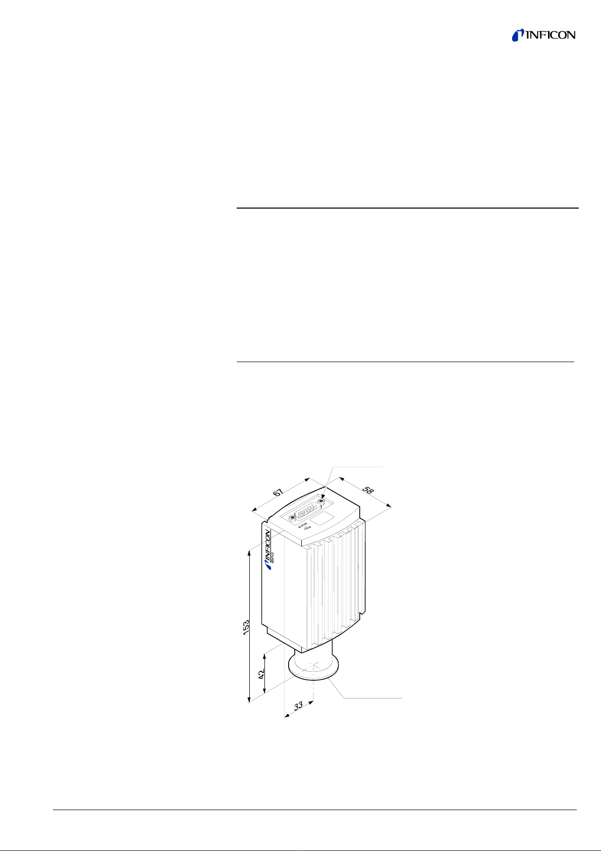
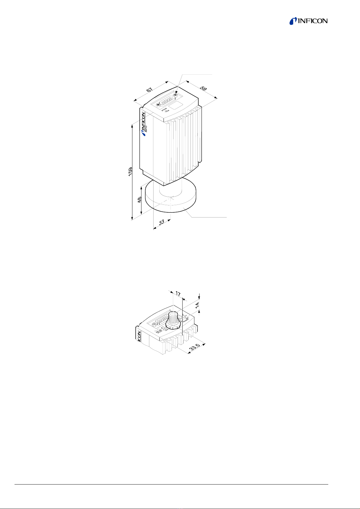
Part numbers
353-500
353-501
353-505
(353-507) 1)
4-40UNC 2B
DN 25 ISO-KF
353-500
353-501
Vacuum
Ambiance
Dimensions
12 tina03e1 (0206) BPG400 v1.om
Part numbers
353-502
353-503
353-506
(353-508) 1)
4-40UNC 2B
DN 40 ISO-KF
353-502
353-503
1) Gauges with DeviceNet connector are 14 mm longer.
The other dimensions of housing and vacuum connection are identical.
Part numbers
353-507
353-508
Weight
353-500, 353-501
353-502, 353-503
353-505, 353-507
353-506, 353-508
285 g
550 g
430 g
695 g

tina03e1 (0206) BPG400 v1.om 13
3 Installation
DANGER
Caution: overpressure in the vacuum system >1 bar
Injury caused by released parts and harm caused by escaping process
gases can result if clamps are opened while the vacuum system is
pressurized.
Do not open any clamps while the vacuum system is pressurized. Use
the type of clamps which are suited to overpressure.
DANGER
Caution: overpressure in the vacuum system >2.5 bar
KF flange connections with elastomer seals (e.g. O-rings) cannot
withstand such pressures. Process media can thus leak and possibly
damage your health.
Use O-rings provided with an outer centering ring.
DANGER
The gauge must be electrically connected to the grounded vacuum
chamber. This connection must conform to the requirements of a
protective connection according to EN 61010:
· CF connections fulfill this requirement
· For gauges with a KF vacuum connection, use a conductive me-
tallic clamping ring.
Caution
Caution: vacuum component
Dirt and damages impair the function of the vacuum component.
When handling vacuum components, take appropriate measures to
ensure cleanliness and prevent damages.
The gauge may be mounted in any orientation. To keep condensates
and particles from getting into the measuring chamber, preferably
choose a horizontal to upright position. See dimensional drawing for
space requirements (®211).
· The gauge is supplied with a built-in grid. For potentially contaminating appli-
cations and to protect the electrodes against light and fast particles, installation
(®217) of the optional baffle is recommended (®247).
· For the vacuum connection sealing, use of a metal seal (®247) is recom-
mended, since elastomer seals (e.g. FPM) can impair the measurement accu-
racy already in the 10-6 mbar range by outgassing.
· The sensor can be baked at up to 150 °C. At temperatures exceeding 50 °C,
the electronics unit has to be removed (®215) or an extension (Option
®247) has to be installed (®216).
3.1 Vacuum Connection

14 tina03e1 (0206) BPG400 v1.om
Remove the protective lid.
The protective lid will be
needed for mainte-
nance.
Make the flange connection.
When installing the gauge, make sure that the area around the con-
nector is accessible for the tools required for adjustment while the gauge
is mounted (®238, 42).
When installing the gauge, allow for installing/deinstalling the connectors
and accommodation of cable loops.
If you are using a gauge with display, make sure easy reading of the
display is possible.
The gauge is now installed.
Procedure
tina03e1 (0206) BPG400 v1.om 15
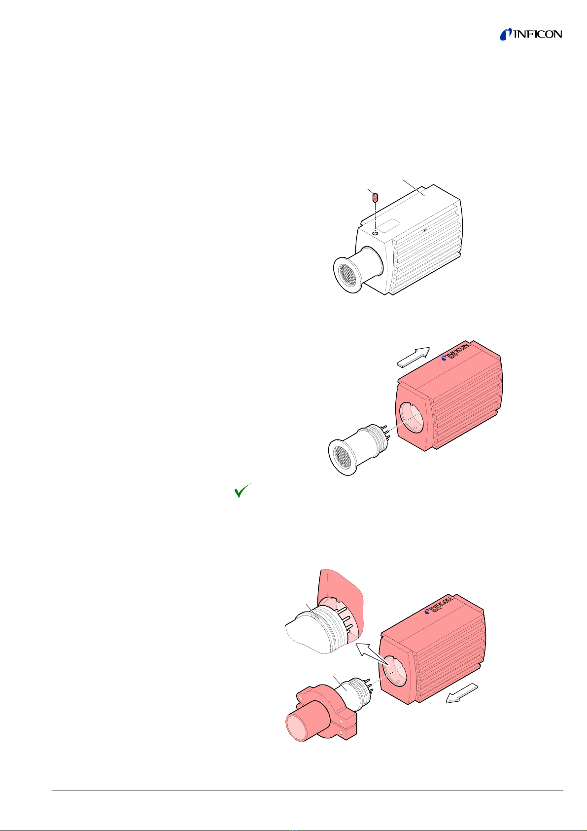
· Allen key, size 2.5 mm
Unscrew the hexagon socket set screw (1) on the side of the electronics
unit (2).
2
1
Remove the electronics unit without twisting it.
Removal of the electronics unit is completed.
Place the electronics unit on the sensor (3) (be careful to correctly align the
pins and notch (4)).
4
3
3.1.1 Removing and Installing
the Electronics Unit
Required tools / material
Removing the electronics unit
Installing the electronics unit
16 tina03e1 (0206) BPG400 v1.om
Slide the electronics unit in to the mechanical stop and lock it with the
hexagon socket set screw (1).
The electronics unit is now installed.
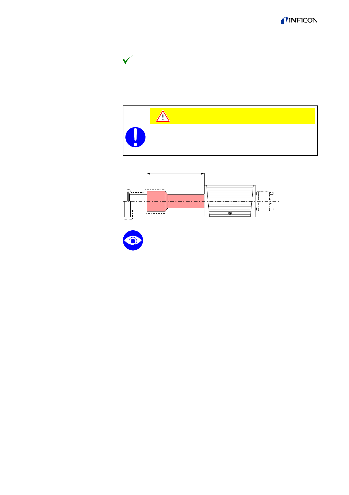
With the optional extension (®247) the sensor can also be baked during opera-
tion at temperatures up to 150 °C (only at p<10-2 mbar because at high tempera-
tures, the accuracy of the Pirani sensor decreases).
Caution
Caution: rising heat
The electronics unit of gauges that are installed vertically, above the
source of heat can be damaged through rising heat even with an
installed extension.
123
Bakeout area
When installing the extension, make sure that the area around the con-
nector is accessible for the tools required for adjustment while the gauge
is mounted (®238, 42).
When installing the gauge, allow for installing/deinstalling the connectors
and accommodation of cable loops.
If you are using a gauge with display, ensure easy reading of the display.
· Extension (®247)
· Allen key, size 2.5 mm
· Allen key, size 1.5 mm
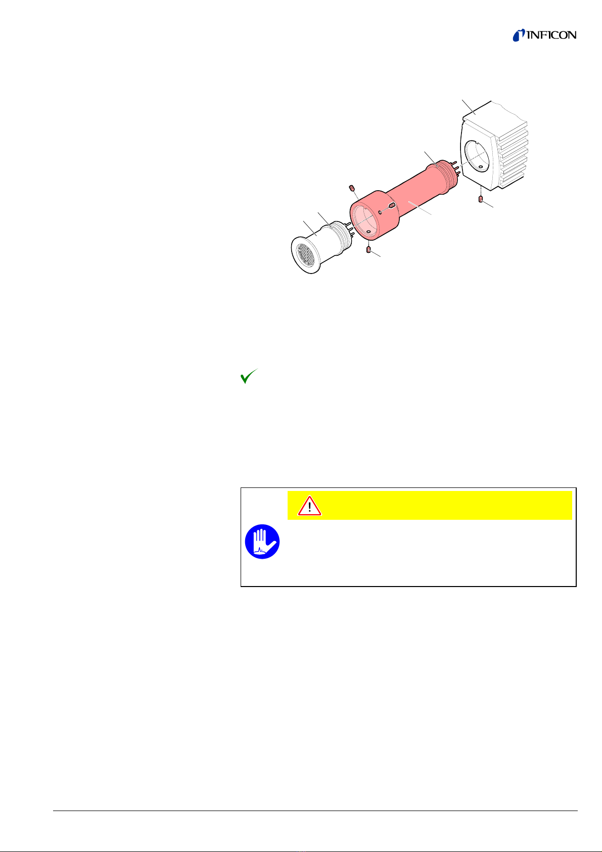
Remove the electronics unit (2) (®215).
Slide the sensor (3) into the extension (6) to the mechanical stop (be careful
to correctly position the pins and notch (4)).
3.1.2 Installing the Optional
Extension
Bakeout area
Required tools / material
Procedure
tina03e1 (0206) BPG400 v1.om 17
Secure the sensor with the hex socket set screws (7) using an Allen key,
size 1.5 mm.
6
7
3
4
4a
2
1
Slide the electronics unit (2) in to the mechanical stop (be careful to cor-
rectly align the pins and notch (4a)).
Secure the electronics unit (2) with the hex socket set screw (1) using an
Allen key, size 2.5 mm.
The extension is now installed.
In severely contaminating processes and to protect measurement electrodes opti-
cally against light and fast particles, replacement of the built-in grid by the optional
baffle (®247) is recommended.
The optional baffle will be installed at the sensor opening of the deinstalled gauge
(Deinstallation ®240).
Caution
Caution: dirt sensitive area
Touching the product or parts thereof with bare hands increases the
desorption rate.
Always wear clean, lint-free gloves and use clean tools when working
in this area.
· Baffle (®247)
· Pointed tweezers
· Pin (e.g. pencil)
3.1.3 Using the Optional Baffle
3.1.3.1 Installing the Baffle
Required tools / material
18 tina03e1 (0206) BPG400 v1.om
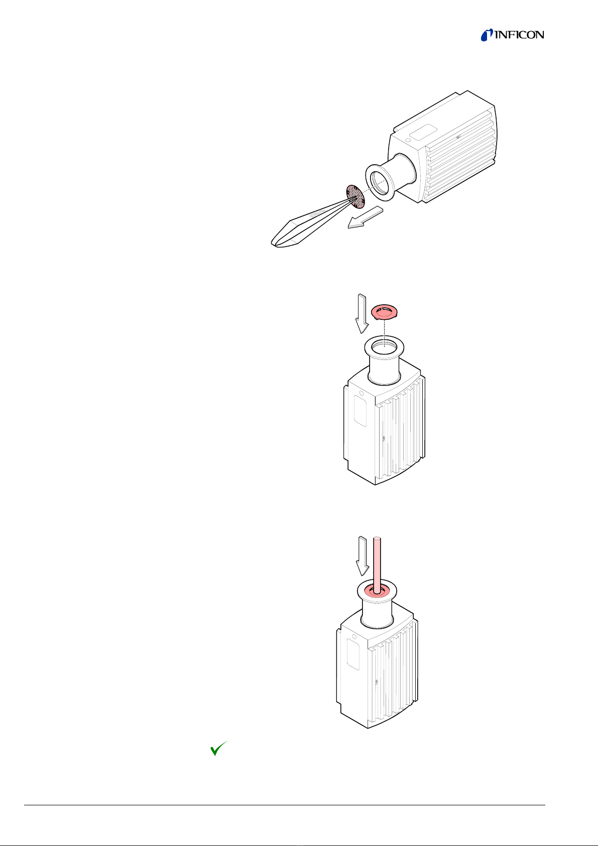
Carefully remove the grid with tweezers.
Carefully place the baffle onto the sensor opening.
Using a pin, press the baffle down in the center until it catches.
The baffle is now installed (Installation of the gauge ®213).
Procedure
tina03e1 (0206) BPG400 v1.om 19
In case of severe contamination the baffle can be easily replaced. For this purpose,
the gauge first has to be deinstalled (Deinstallation of the gauge ®240).
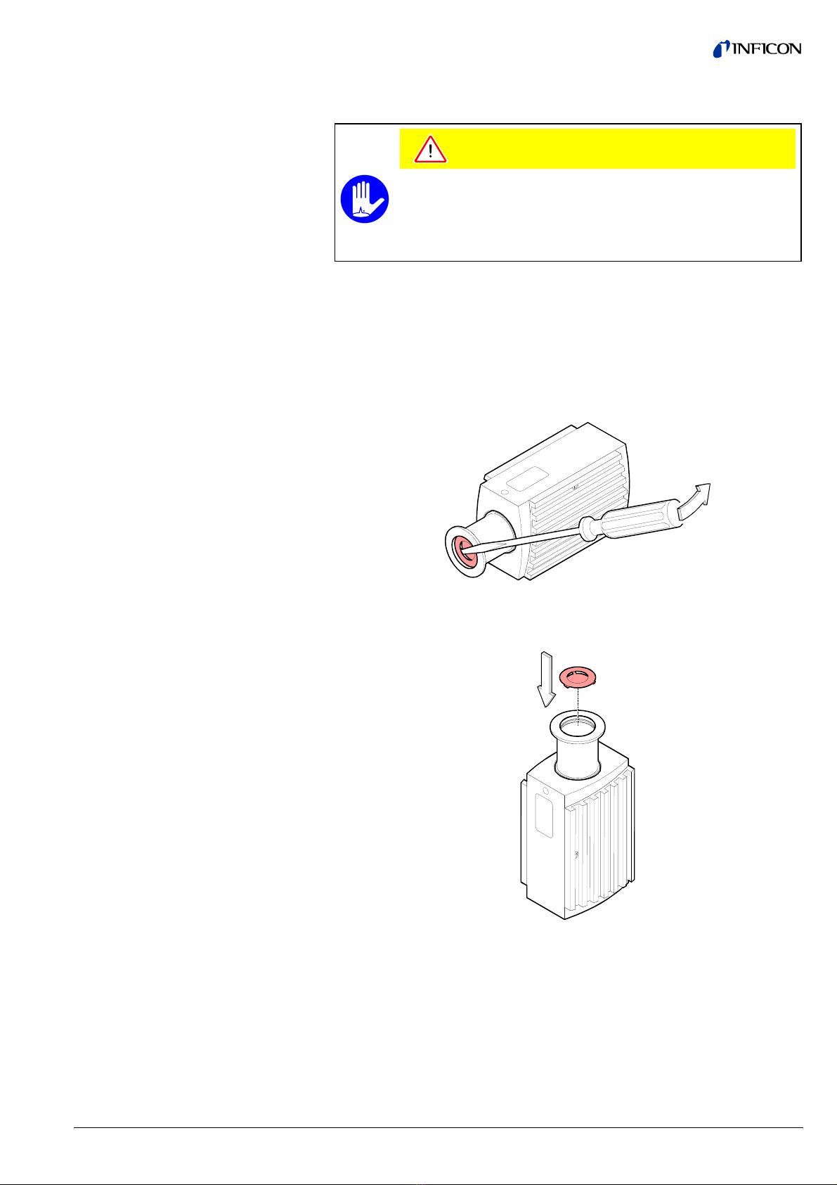
Caution
Caution: dirt sensitive area
Touching the product or parts thereof with bare hands increases the
desorption rate.
Always wear clean, lint-free gloves and use clean tools when working
in this area.
· New baffle (®247)
· Screwdriver No 1
· Pin (e.g. pencil)
Carefully remove the baffle with the screwdriver.
Place new baffle carefully onto the sensor opening.
3.1.3.2 Replacing the Baffle
Required tools / material
Procedure
20 tina03e1 (0206) BPG400 v1.om
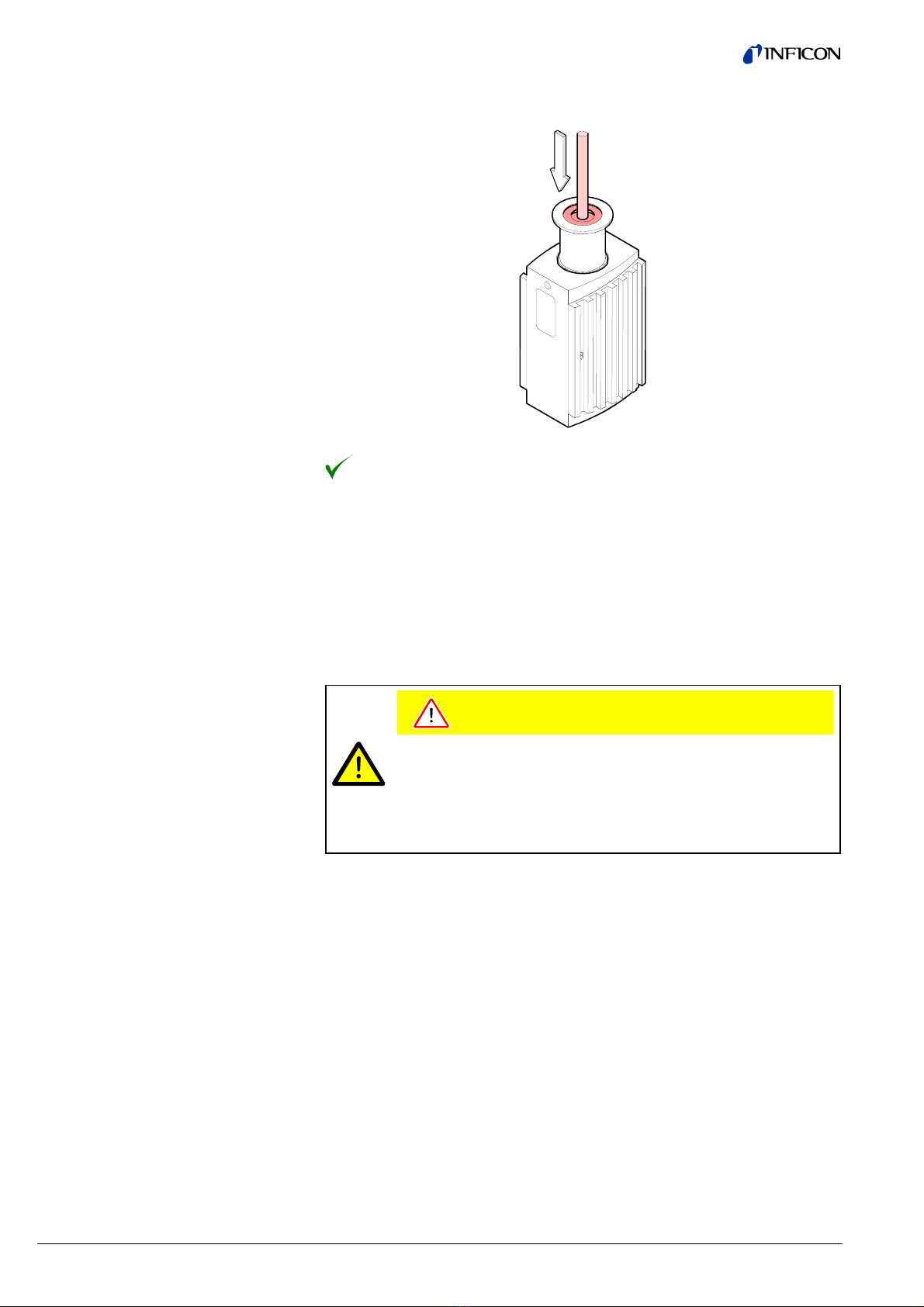
Using a pin, press the baffle down in the center until it catches.
The new baffle is now installed (Installation of the gauge ®213).
If the gauge is used with an INFICON VGC103 or VGC40x controller, a corre-
sponding sensor cable is required (®247). The sensor cable permits supplying
the gauge with power, transmitting measurement values and gauge statuses, and
making parameter settings.
Caution
Caution: data transmission errors
If the gauge is operated with the INFICON VGC103 or VGC40x
Vacuum Gauge Controller (RS232C) and a fieldbus interface at the
same time, data transmission errors may occur.
The gauge must not be operated with an INFICON VGC103 or
VGC40x controller and DeviceNet or Profibus at the same time.
· Sensor cable for INFICON controllers (®247)
3.2 Electrical Connection
3.2.1 Use With INFICON
VGC103 or VGC40x
Vacuum Gauge
Controller
Required material
Other manuals for BPG400
1
This manual suits for next models
2
Table of contents
Other Inficon Accessories manuals


