Inficon RSH-600 User manual

OPERATING MANUAL
RSH-600
Rotary Sensor Head
PN 153800-L
C
over
P
age

Trademarks
The trademarks of the products mentioned in this manual are held by the companies that
produce them.
Scotch-Brite®is a registered trademark of 3M.
Teflon®and Kapton®are registered trademarks of E. I. du Pont de Nemours and Company or its affiliates.
All other brand and product names are trademarks or registered trademarks of their respective companies.
Disclaimer
The information contained in this manual is believed to be accurate and reliable. However, INFICON assumes
no responsibility for its use and shall not be liable for any special, incidental, or consequential damages related
to the use of this product.
Due to our continuing program of product improvements, specifications are subject to change without notice.
Copyright
©2018 All rights reserved.
Reproduction or adaptation of any part of this document without permission is unlawful.

1–1
RSH-600 Operating Manual
Table Of Contents
Trademarks
Disclaimer
Copyright
Chapter 1
Introduction
1.1 Introduction. . . . . . . . . . . . . . . . . . . . . . . . . . . . . . . . . . . . . . . . . . . . . . . . . . 1-1
1.2 Safety . . . . . . . . . . . . . . . . . . . . . . . . . . . . . . . . . . . . . . . . . . . . . . . . . . . . . . 1-2
1.3 How to Contact INFICON . . . . . . . . . . . . . . . . . . . . . . . . . . . . . . . . . . . . . . . 1-2
1.4 Returning Your RSH-600 . . . . . . . . . . . . . . . . . . . . . . . . . . . . . . . . . . . . . . . 1-3
1.5 Unpacking and Inspection . . . . . . . . . . . . . . . . . . . . . . . . . . . . . . . . . . . . . . 1-3
1.6 Base Configuration . . . . . . . . . . . . . . . . . . . . . . . . . . . . . . . . . . . . . . . . . . . . 1-4
1.7 Specifications . . . . . . . . . . . . . . . . . . . . . . . . . . . . . . . . . . . . . . . . . . . . . . . . 1-5
1.8 Replacement Parts and Accessories . . . . . . . . . . . . . . . . . . . . . . . . . . . . . . 1-6
Chapter 2
Installation
2.1 Configurations . . . . . . . . . . . . . . . . . . . . . . . . . . . . . . . . . . . . . . . . . . . . . . . 2-2
2.2 Functional Verification . . . . . . . . . . . . . . . . . . . . . . . . . . . . . . . . . . . . . . . . . 2-3
2.3 Crystal Sensor Installation . . . . . . . . . . . . . . . . . . . . . . . . . . . . . . . . . . . . . . 2-4
2.4 Mounting. . . . . . . . . . . . . . . . . . . . . . . . . . . . . . . . . . . . . . . . . . . . . . . . . . . . 2-5
2.5 Adjustable Flange Installation. . . . . . . . . . . . . . . . . . . . . . . . . . . . . . . . . . . . 2-6
2.6 Copper Head Installation . . . . . . . . . . . . . . . . . . . . . . . . . . . . . . . . . . . . . . . 2-8
2.7 Cooling System . . . . . . . . . . . . . . . . . . . . . . . . . . . . . . . . . . . . . . . . . . . . . . 2-8
2.8 Air Supply . . . . . . . . . . . . . . . . . . . . . . . . . . . . . . . . . . . . . . . . . . . . . . . . . . . 2-8
2.9 Crystal Position Feedback Connections. . . . . . . . . . . . . . . . . . . . . . . . . . . . 2-9
2.10 Protection from Evaporant . . . . . . . . . . . . . . . . . . . . . . . . . . . . . . . . . . . . . . 2-9
Chapter 3
Troubleshooting and Maintenance
3.1 Troubleshooting . . . . . . . . . . . . . . . . . . . . . . . . . . . . . . . . . . . . . . . . . . . . . . 3-1
3.2 Troubleshooting RSH-600 . . . . . . . . . . . . . . . . . . . . . . . . . . . . . . . . . . . . . . 3-1
3.3 Maintain the Temperature of the Crystal . . . . . . . . . . . . . . . . . . . . . . . . . . . 3-4
3.4 Use the Optimum Crystal Type . . . . . . . . . . . . . . . . . . . . . . . . . . . . . . . . . . 3-4
3.5 Crystal Concerns when Opening the Chamber . . . . . . . . . . . . . . . . . . . . . . 3-4
3.6 Crystal Holder Maintenance . . . . . . . . . . . . . . . . . . . . . . . . . . . . . . . . . . . . . 3-4
3.7 Crystal Replacement . . . . . . . . . . . . . . . . . . . . . . . . . . . . . . . . . . . . . . . . . . 3-5
Chapter 4
Outline Drawings

1–1
RSH-600 Operating Manual
Chapter 1
Introduction
1.1 Introduction
The RSH-600 rotary sensor is designed for the most demanding processes
employing very thick films and several different materials. See Figure 1-1.
Switching the crystal without venting the system makes it possible to run
automatically with continuous deposition. The fixed position of the crystal being
measured also makes it unnecessary to change the tooling factor.
RSH-600 can be used to deposit a different material on each of six crystals
providing greater measurement accuracy. Upon completion of deposition of one
material, the deposition controller may be programmed to switch crystals for the
next material. Switching crystals may also be actuated manually.
The RSH-600 sensor holds six crystals in a thermally shielded, water cooled
housing, insuring excellent crystal performance in temperature environments up to
300ºC. Crystals are housed in an easily removable Teflon®and stainless steel
crystal holder.
Crystal position is switched by applying a one second pulse to a 110/115 V (ac) or
24 V (dc) pneumatic valve. A 7-pin connector provides an indication of the number
of the active crystal. This may be used to interface with a thin film controller for
automatic crystal switching operation. Refer to the controller operating manual for
programming instructions.
Figure 1-1 RSH-600 and sensor head options
1–2
RSH-600 Operating Manual
1.2 Safety
When using this manual, please pay attention to the Notes, Cautions, and Warnings
found throughout. For the purposes of this manual they are defined as follows:
NOTE: Pertinent information that is useful in achieving maximum efficiency
when followed.
CAUTION
Failure to heed these messages could result in damage
to the instrument.
WARNING
Failure to heed these messages could result in
personal injury.
1.3 How to Contact INFICON
Worldwide customer support information is available under Support at
www.inficon.com where you can contact:
a Technical Support Engineer with questions regarding applications.
a Service Engineer with questions regarding troubleshooting, diagnosing or
repairing a defective sensor.
Sales and Customer Service, to find the INFICON Sales office nearest to you.
Repair Service, to find the INFICON Service Center nearest to you.
If you are experiencing a problem with RSH-600, please have the following
information readily available:
the serial number of RSH-600,
a description of your problem,
an explanation of any corrective action that you may have already attempted,
and the exact wording of any error messages that you may have received.

1–3
RSH-600 Operating Manual
1.4 Returning Your RSH-600
Do not return any component of your sensor to INFICON without first speaking with
a Customer Support Representative. You must obtain a Return Material
Authorization (RMA) number from the Customer Support Representative.
If you deliver a package to INFICON without an RMA number, your package will be
held and you will be contacted. This will result in delays in servicing your instrument.
Prior to being given an RMA number, you may be required to complete a
Declaration of Contamination (DOC) form if your sensor has been exposed to
process materials. DOC forms must be approved by INFICON before an RMA
number is issued. INFICON may require that the sensor be sent to a designated
decontamination facility, not to the factory.
1.5 Unpacking and Inspection
1If the RSH-600 sensor has not been removed from its shipping container, do
so now.
2Carefully examine the RSH-600 sensor for damage that may have occurred
during shipping. This is especially important if there is obvious rough handling
on the outside of the container. Immediately report any damage to the carrier
and to INFICON.
3Do not discard the packing materials until inventory is taken and a functional
verification test is performed. See section 2.2.
4Take an inventory of the order by referring to the order invoice and verifying that
the items listed in section 1.6 were received.
1–4
RSH-600 Operating Manual
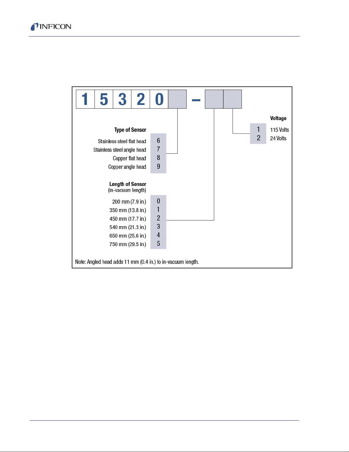
1.6 Base Configuration
RSH-600 Rotary Sensor Head. . . . . . . . . . . . . . . . . . . . . . . . . . . . . . . 15320X-XX
See Figure 1-2 below for possible configurations.
Figure 1-2 RSH-600 configurations
Crystals (2 boxes, 10 total) . . . . . . . . . . . . . . . . . . . . . . . . . . . . . . . . . . . 103200-2
Technical Manual . . . . . . . . . . . . . . . . . . . . . . . . . . . . 153800 on 074-5000-G1 CD

1–5
RSH-600 Operating Manual
1.7 Specifications
Number of Crystals: 6
Crystal Size . . . . . . . . . . . . . . . . . . . 14 mm (0.550 in.) diameter
Installation Aperture: . . . . . . . . . . . . 5.08 cm (2.0 in.) diameter
Overall Length
RSH-600 w/flat head . . . . . . . . . 208 mm (8.19 in.) plus in-vacuum length
RSH-600 w/angled head . . . . . . 219 mm (8.62 in.) plus in-vacuum length
Adjustable in-vacuum Length . . . 200 mm (7.9 in.) (standard)
350 mm (13.8 in.)
450 mm (17.7 in.)
540 mm (21.3 in.)
650 mm (25.6 in.)
Power Requirement . . . . . . . . . . . . . 115 V (ac) @ 50 mA or 24 V (dc) @ 20 mA
Crystal Switching Method. . . . . . . . . Air Actuated @ 55 psi (4 kg/cm2) regulated
Cooling Method . . . . . . . . . . . . . . . . Water-cooled @ 5 L/m at 2 kg/cm2(28 psi)
Air and Water Connections. . . . . . . . (3) 6.35 mm (1/4 in.) quick connects
Operating Temperature. . . . . . . . . . . 300°C max with water cooling and Standard
Head Cover
400°C max with water cooling and Copper
Head Cover
Weight: (standard length) . . . . . . . . 200 mm (7.9 in.) RSH-600 - Flat - 3.8 kg
(8.5 lb.)
RSH-600 - Angled - 4.5 kg (9.9 lb.)

1–6
RSH-600 Operating Manual
1.8 Replacement Parts and Accessories
Flat Copper Head Cover . . . . . . . . . . . . . . . . . . . . . . . . . . . . . . . . . . . . . . 153731
Angled Copper Head Cover . . . . . . . . . . . . . . . . . . . . . . . . . . . . . . . . . . . 153731-2
Flat Stainless Steel Head Cover (See Figure 1-3) . . . . . . . . . . . . . . . . . . . 153708
Angled Stainless Steel Head Cover (See Figure 1-4) . . . . . . . . . . . . . . . . 153713
Flat Crystal Retainer Assembly (See Figure 1-3). . . . . . . . . . . . . . . . . . . . 153204
Angled Crystal Retainer Assembly (See Figure 1-4) . . . . . . . . . . . . . . . . 153204-2
Flat Crystal Holder (See Figure 1-3) . . . . . . . . . . . . . . . . . . . . . . . . . . . . . 153710
Angled Crystal Holder (See Figure 1-4) . . . . . . . . . . . . . . . . . . . . . . . . . . . 153716
Flat Spring Retainer Assembly (See Figure 1-3) . . . . . . . . . . . . . . . . . . . . 153706
Angled Spring Retainer Assembly (See Figure 1-4) . . . . . . . . . . . . . . . . . 153714
Flat Spring Retainer Contact Kit (See Figure 1-3) . . . . . . . . . . . . . . . . . . . 153724
Spring Contact (See Figure 1-3 and Figure 1-4) . . . . . . . . . . . . . . . . . . . . 153726
Flat Retainer Screw (See Figure 1-3) . . . . . . . . . . . . . . . . . . . . . . . . . . . . 153709
Angled Retainer Screw (See Figure 1-4) . . . . . . . . . . . . . . . . . . . . . . . . . . 153715
Angled Retainer Spacer (See Figure 1-4) . . . . . . . . . . . . . . . . . . . . . . . . . 153717
M3x6 Screw for Flat Crystal Retainer Assembly (See Figure 1-3). . . . . . . 144-101
M3x12 Screw for Angled Crystal Retainer Assembly (See Figure 1-4) . . . 144-224
Solenoid Valve Assembly, 24 V (See Figure 4-1). . . . . . . . . . . . . . . . . . . . 153707
Crystal Position Male Connector (See Figure 4-1). . . . . . . . . . . . . . . . . . . 889128
Adjustable Flange (See Figure 4-1 and Figure 4-2). . . . . . . . . . . . . . . . . . 153202
O-ring for Adjustable Flange (See Figure 4-1) . . . . . . . . . . . . . . . . . . . . . . 803188

1–7
RSH-600 Operating Manual
Figure 1-3 Rotary sensor head - flat
Stainless Steel Cover
Crystal Holder
P/N 153708
P/N 153710
Spring Contact
Retainer Screw
Spring Retainer
Spring Retainer
P/N 153726
P/N 153709
Copper Cover (not shown)
P/N 153731
Contact Kit (set of 6)
P/N 153724
Assembly
P/N 153706
Crystal Retainer
Assembly
P/N 153204

1–8
RSH-600 Operating Manual
Figure 1-4 Rotary sensor head - angled
Stainless Steel Cover
Copper Cover (not shown)
Crystal Holder
P/N 153716
P/N 153713
P/N 153731-2
Spring Retainer
Assembly
P/N 153714
Crystal Retainer
Assembly
P/N 153204-2
Retainer Screw
P/N 153715
M3x12 Screw
P/N 144-224
Spring Contact
P/N 153726
Retainer Spacer
P/N 153717

2–1
RSH-600 Operating Manual
Chapter 2
Installation
CAUTION
During installation, special care must be taken to protect
the barrel surface from being damaged. Scratches or
gouges may prevent RSH-600 from forming a good
vacuum seal to the O-ring.
Successful operation of any crystal sensor depends on proper placement,
compatibility of its construction with its operating environment and connection to
proper utilities.
CAUTION
RSH-600 must be clean and grease free when installed in
the vacuum chamber. The sensor must be handled while
wearing clean nylon gloves. If parts do become
contaminated, clean them thoroughly using a suitable
solvent to avoid outgassing and excessive peeling of
deposition material from the sensor surfaces.

2–2
RSH-600 Operating Manual
2.1 Configurations
RSH-600 can be configured with a flat head or a 45° angled head. This allows for
mounting in various locations within the vacuum chamber. Standard head covers are
made of stainless steel. Copper head covers are available for applications where
temperature is a concern (see
Figure 2-1
). All versions of RSH-600 are fixed to their
specified lengths, but may be adapted to be adjustable in length using the optional
adjustable mounting flange (see
section 1.8
for optional accessory information).
Figure 2-1 RSH-600 sensor head cover cooling efficiency

2–3
RSH-600 Operating Manual
2.2 Functional Verification
RSH-600 is equipped to operate on a 115 V (ac), 60 Hz line or a 24 V (dc) supply,
depending on the model number. The required voltage on the body of the
pneumatic valve mounted on the side of RSH-600 can be verified. RSH-600 may
be bench checked using the following procedure:
1Connect air pressure (55 psi) via 6.35 mm (1/4 in.) plastic tubing to the air inlet
fitting at the base of the solenoid valve marked "P."
2Connect RSH-600 as shown in Figure 2-2 or use any convenient method of
applying and removing the control voltage. RSH-600 will advance when the
voltage is applied and latch into position when it is removed. The electrical
pulse duration should be at least one second.
Figure 2-2 Electrical connection
Control
Voltage
115 V (ac)
or
24 V (dc)
J1 RSH
Switch

2–4
RSH-600 Operating Manual
2.3 Crystal Sensor Installation
Install the sensor as far as possible from the evaporation source (a minimum of
30.5 cm (12 in.)) while still being in a position to accumulate thickness at a rate
proportional to accumulation on the substrate. Figure 2-3 shows proper and
improper methods of installing sensors.
Figure 2-3 Sensor installation guidelines
To guard against spattering, use a source shutter to shield the sensor during the
initial soak periods. If the crystal is hit with even a minute particle of molten material
it may be damaged and stop oscillating. Even in cases when it does not completely
stop oscillating, it may immediately become unstable, or shortly after deposition
begins instability may occur.
Plan the installation to ensure that there are no obstructions blocking a direct path
between the sensor and the source. Install sensors in such a manner that the
center axis of the crystal is aimed directly at the source to be monitored. Verify that
the angle of the sensor location (with reference to the source) is well within the
evaporant stream.

2–5
RSH-600 Operating Manual
2.4 Mounting
The RSH-600 smooth sealing surface mounts to an O-ring sealed nipple (not
included). The optional adjustable flange allows the in-vacuum length to be
adjustable up to the RSH-600 original length. A flat head cover is typically used for
centered top mount applications while the angled heads may be used for either
off-center top mount or side mount applications. The customer must supply
specifications regarding mounting holes, exterior diameter of flange, and the
system mating flange.
NOTE: The head cover must be removed from RSH-600 prior to installation.
To remove the standard stainless steel head cover: loosen the retainer ring
nut. Push the head cover inward while turning it counterclockwise until it
stops (1/16 of a turn). Pull the head cover outward.
To remove the optional copper head cover: loosen the Allen head screws
that clamp the head to RSH-600 then gently pull the head off of the
RSH-600 barrel.
The vacuum system must be equipped with a 5.08 cm (2.0 in.) diameter aperture
port. This port must have an O-ring to provide vacuum seal to the fixed flange on
RSH-600. If the head cover has been removed, simply slide RSH-600 through the
5.08 cm (2.0 in.) port. Secure RSH-600 to the port using four 1/4-24 bolts minimum.
Reinstall the head cover. See Figure 2-4.
Figure 2-4 Typical mounting configuration
J2
J1
15.24 cm (6 in.) Coaxial Cable
Oscillator
3 m (10 ft.) Coaxial Oscillator
Water In
Optional Flange
Water Out
Air Solenoid Valve
Cable to QCM

2–6
RSH-600 Operating Manual
2.5 Adjustable Flange Installation
1Apply a small amount of vacuum compatible grease to the entire surface of the
O-ring that is included with the adjustable flange and then install the O-ring into
the O-ring groove in the adjustable flange.
2Loosen the hex socket head screw on the adjustable flange.
3Remove the cover from the RSH-600 sensor.
4If the crystal holder contains any crystals, remove the holder and remove and
discard the crystals. Reinstall the crystal holder.
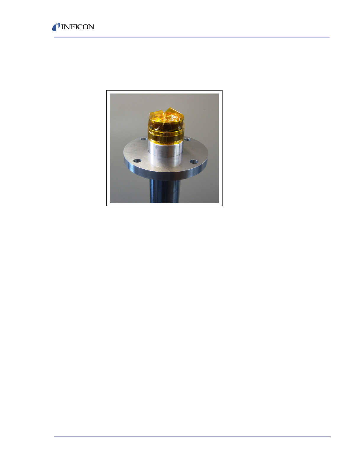
5Cut a piece of Kapton® tape (or equivalent), 3.8 cm (1.5 in.) to 5.08 cm (2 in.)
wide, to a length of approximately 16 cm (6.3 in.).
6Position the Kapton tape with the bottom edge of the tape on the beveled
surface just below the knurled ring. Not starting at any of the three bayonet
pins, wrap the tape around the circumference of the sensor. Fold the excess
tape over the top of the crystal holder. See Figure 2-5.
Figure 2-5 Wrap Kapton tape
2–7
RSH-600 Operating Manual
7Stand the RSH-600 sensor upright on a firm surface. Place the adjustable
flange, with smooth side up, over the top of the sensor barrel. With the flange
seating surface perpendicular to the sensor barrel, forcefully push the flange
downward, sliding the flange onto the sensor barrel. See Figure 2-6.
Figure 2-6 Slide flange onto sensor barrel
8Slide the adjustable flange to the desired position on the sensor barrel and then
secure the flange to the barrel by tightening the hex socket head screw on the
flange.
9Remove the Kapton tape. Use a lint-free cloth dampened with reagent grade
isopropyl alcohol to clean the surfaces that were in contact with the tape.

2–8
RSH-600 Operating Manual
2.6 Copper Head Installation
The optional copper head must be installed after RSH-600 has been mounted on
the vacuum system. The copper head has two main pieces, the clamping ring and
the head cover.
1Loosen the Allen head screw on the clamping ring and on the clamp portion of
the head cover.
2Attach the clamping ring to the head cover.
3Remove the crystal retainer to expose two gold springs. One spring makes
contact with the backside of the retainer. The other spring makes contact with
one of the individual crystal contacts.
4Align the hole in the head cover so that the crystal, that this spring contacts, is
exposed. Note the position of this spring and replace the crystal retainer.
5Carefully slide the cover over the barrel of RSH-600 until it touches the crystal
retainer, then rotate the cover so that the crystal, in contact with the spring, is
centered in the hole in the cover.
6Tighten the Allen screws on the clamping ring.
The clamping ring should be left attached to the head during crystal changing. Only
the head cover should be removed so the alignment process will not have to be
repeated unless the head is removed from the chamber.
If no flange was ordered and dimensions are needed for a custom adjustable
flange, INFICON can provide essential dimensions and O-rings.
2.7 Cooling System
The direction of the water flow is not important. Use 6.35 mm (1/4 in.) plastic tubing
to connect one port to a water supply. The water flow rate should be 5 L/m (1.3 g/m)
at 2 kg/cm2(28 psi). Water temperature should be less than 30°C. Connect the
other port to a drain or water recycle system.
2.8 Air Supply
Use 6.35 mm (1/4 in.) plastic tubing to connect the air inlet port to an air supply.
Make sure the plastic tube is rated higher than 55 psi. The air pressure should be
regulated to 4 kg/cm2(55 psi).
2–9
RSH-600 Operating Manual
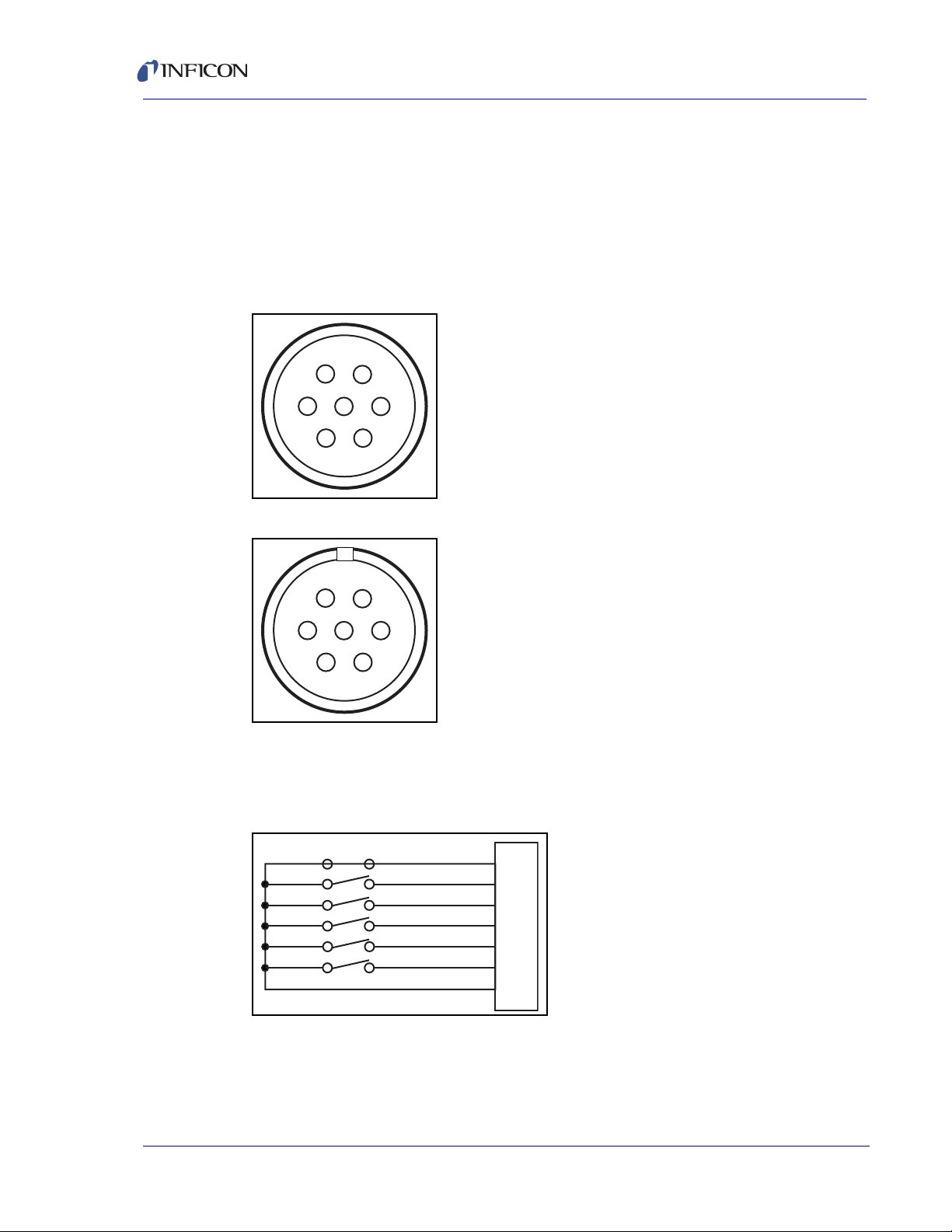
2.9 Crystal Position Feedback Connections
The crystal position connector has seven pins. Pin numbers 1 through 6
correspond to the six crystals and pin number 7 is the common pin. A short
between pin 7 and one of the pins 1 through 6 indicates the active crystal. For
example, if pin 7 is shorted to pin 1, then crystal 1 is the active crystal.
Use this connector to interface with the controller for automatic crystal selection.
Refer to the controller operating manual for programming instruction.
Figure 2-7 Crystal position connector
Figure 2-8 Mating connector (male) - crystal position connector
RSH-600 provides a switch closure through connector J2 that can be used to
indicate which crystal is active at a given time. Switch closure will be affected by
crystal positions.
Figure 2-9 Crystal position feedback diagram (crystal 1 is the active crystal)
2.10 Protection from Evaporant
Place aluminum foil over the RSH-600 head cover and barrel to protect them from
evaporants during a vacuum operation.
1
2
34
5
6
7
6
5
43
2
1
7
Common
Crystal 1
Crystal 2
Crystal 3
Crystal 4
Crystal 5
Crystal 6
1
2
3
4
5
6
7
Table of contents
Other Inficon Accessories manuals


Popular Accessories manuals by other brands


Lifetime
Lifetime FREESTANDINGPOWER LIFT 71730 Owner's manual with assembly instructions

Vaisala
Vaisala HMP60 series user guide

Black & Decker
Black & Decker BDXPA0042 instruction manual

Vuly
Vuly THUNDER Assembly manual

Tascam
Tascam US-122 owner's manual

Honeywell
Honeywell Farenhyt Series Installation and maintenance instructions


