Inficon Easy Rate ERD E1 Series User manual

1 of 13
Easy Rate™ Sensor
INSTRUCTION SHEET
PN 074-677-P1A
Introduction
This instruction sheet describes the proper installation, operation, maintenance, and
repair of the Easy Rate single and dual sensors.
This product has a warranty of one year from the date of purchase. This warranty covers
defects of materials or workmanship under normal proper use and service. Refer to the
INFICON website for warranty details. The batch number of the sensor can be found on
the packaging label. It is important to document this number for any necessary warranty
claims.
Figure 1 Easy Rate Sensors
2 of 13
Easy Rate Sensor
PN 074-677-P1A
Installation
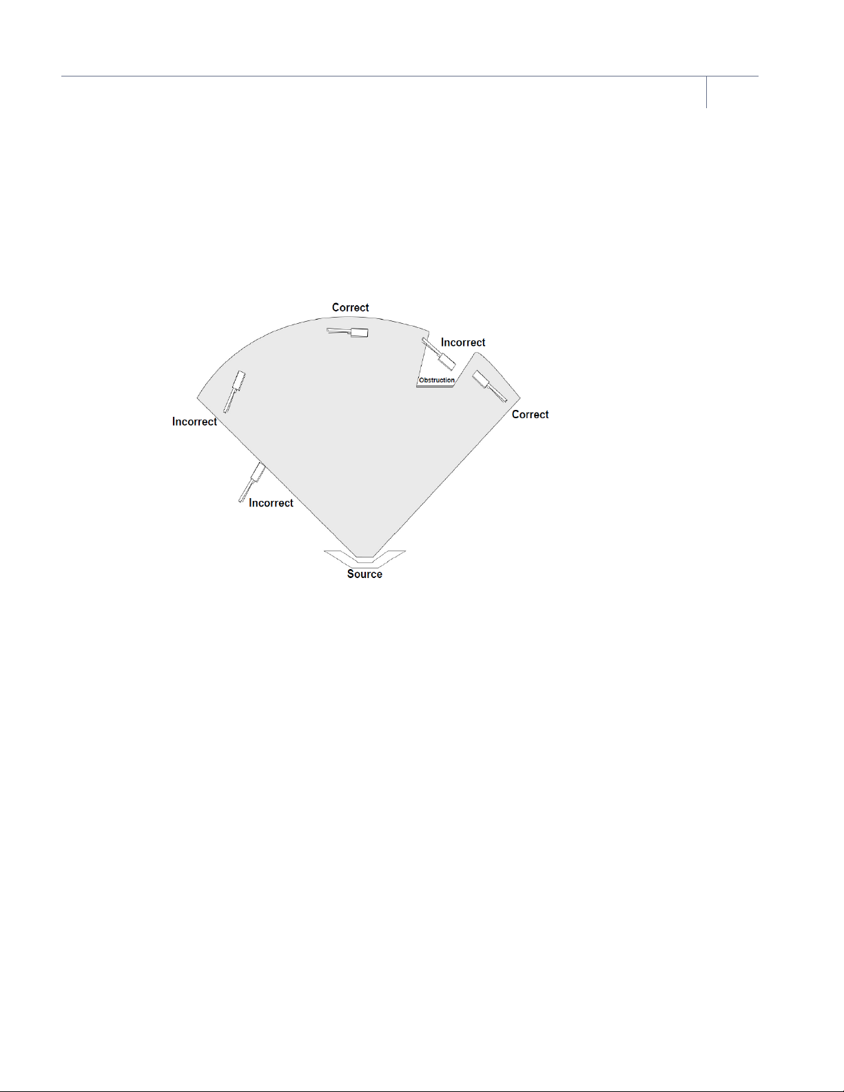
Install the sensor as far as possible from the evaporation source (a minimum of 25.4 cm
(10 in.)) while still being in a position to accumulate thickness at a rate proportional to
accumulation on the substrate. Figure 2 shows proper and improper methods of
installing sensors.
Figure 2 Proper and improper methods of installing sensors
NOTE: For best process reproducibility, rigidly support the sensor by the #4-40 screw
mounting holes on the back of the sensor so it cannot move during maintenance
and crystal replacement.
To guard against spattering, use a source shutter to shield the sensor during initial soak
periods. If the crystal is hit with even a minute particle of molten material, it may be
damaged and stop oscillating. Even in cases when it does not completely stop
oscillating, it may immediately become unstable or, shortly after deposition begins,
instability may occur.
Plan the installation to ensure there are no obstructions blocking a direct path between
the sensor and the source. Install sensors in such a manner that the crystal face is aimed
directly at the source to be monitored. Verify that the angle of the sensor location (with
reference to the source) is well within the evaporant stream. If the sensor is not
perpendicular to the source, the coating on the crystal will be tapered and shortened
crystal life can result.
3 of 13
Easy Rate Sensor
PN 074-677-P1A
NOTE: In many cases, installing multiple sensors to monitor one source can improve
thickness accuracy for the product, using a feature known as multiple sensor
averaging. The installation requirements for multiple sensors are the same as for
a single sensor installation, and the locations chosen should be as defined in
Figure 2. Consult the Quartz Crystal Microbalance (QCM) thickness
measurement instrument operating manual for more information regarding the
availability of this feature.
Steps for installation:
1Assemble the sensor mounting bracket (provided by customer) on the process
system.
2Temporarily position and attach the sensor head as outlined in the general guidelines
in Figure 2.
3Temporarily install the feedthrough.
4Form (bend), measure, and mark the sensor tubes as required to achieve the desired
result.
CAUTION
Do not form the sensor tubes with a bend radius of less than
1.3 cm (0.5 in.).
CAUTION
Do not use the sensor body as a leverage point when bending
the tubes; doing so stresses the weld joints on the tubes and
may result in their failure.
CAUTION
Do not start a bend within 1.3 cm (0.5 in.) of a weld joint.
5Build the sensor/feedthrough assembly.
6Remove the sensor and the feedthrough.
7Cut the water cooling tubes and the air tube to the proper length. Verify that they are
clear of metal particles by forcing compressed air through the tubing.
8Connect the water cooling tubes and the air tube directly to the feedthrough, or use
vacuum rated couplings.

4 of 13
Easy Rate Sensor
PN 074-677-P1A
Vacuum rated connectors are recommended for use between the sensor and the
feedthrough to speed maintenance. If brazing adapters are to be used, attach them
to the sensor water-cooling tubes and to the air tube prior to connection to the
feedthrough. Make connections as follows:
CAUTION
To prevent damage to the feedthrough or sensor during
brazing, ensure that at least 2.45 cm (1 in.) of water tube
remains between the sensor head and the flame.
8a Clean the water tubes, the air tube, and adapter surfaces with solvent, if necessary.
8b Apply brazing flux to surfaces being joined.
8c Braze the connections using a flame temperature appropriate for the brazing
material being used.
CAUTION
Excessive application of brazing material, or excessive heat
due to brazing, may result in blockage of the water tubes or the
air tube.
8d Verify that each joint is not blocked by blowing compressed air through the cooling
tubes and the air tube.
8e Thoroughly clean the braze joint and helium leak test before installing the sensor and
feedthrough into the process chamber.
9With all water tube connections and the air tube connection installed, install the
sensor and feedthrough assembly into the process system and secure all retaining
hardware.
10 Shield the in-vacuum cable from heat radiating from the evaporant source or the
substrate heater. If the process allows, wrap aluminum foil around the cable, the
water tubes and the air tube.
11 Connect the external water tubes from the feedthrough to the water supply system
and flow controller. Use detachable coupling (Swagelok®or equivalent) for external
water tube connections. Apply water pressure and verify the water connections.
12 Because of geometric factors, variations in surface temperature, and differences in
electrical potential, the crystal and substrates often do not receive the same amount
of material. Tooling factor calibration is required to make sure that the thickness
indication on the instrument accurately represents the thickness on the substrates.
Refer to the instrument operating manual for tooling factor calibration procedures.
5 of 13
Easy Rate Sensor
PN 074-677-P1A
Actuator Function Check
Temporarily connect an air supply to the actuator air tube and test operation for 10 to 15
cycles. Operating range is:
70–80 psi (gauge)
85–95 psi (absolute)
5.8–6.5 bar (absolute)
584–653 kPa (absolute)
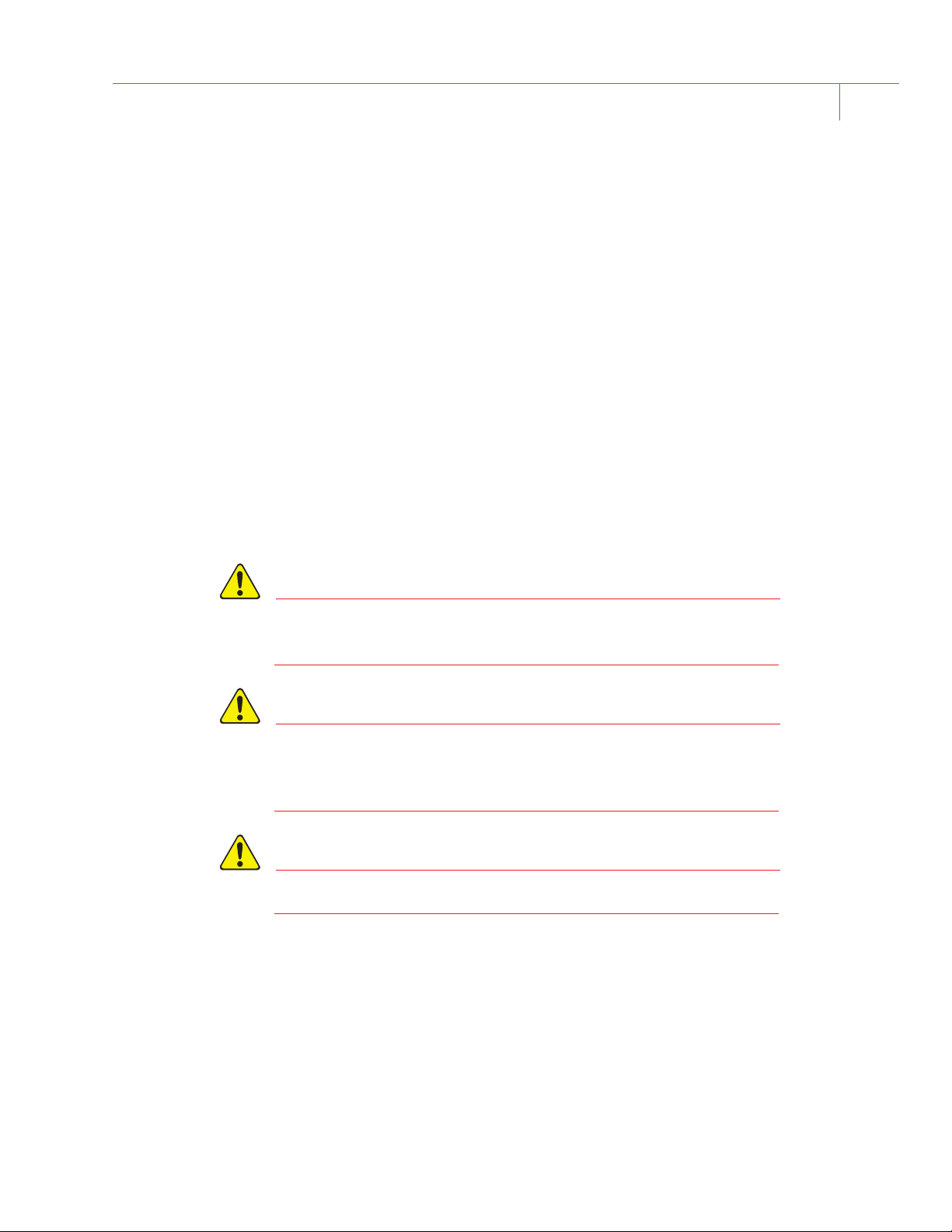
When actuated, shutter movement should be smooth, rapid, and complete, and should
extend as shown. The crystal aperture must be completely exposed. It is acceptable if
the crystal holder is only partially exposed. (See Figure 3.)
Figure 3 Acceptable shutter end extension
When deactivated, the shutter should completely cover the crystal opening.
Repositioning of the shutter or actuator may be required to achieve optimum on/off
positioning. If operation is found to be impaired, contact INFICON. (See Figure 4.)
Figure 4 Shutter completely covering the crystal opening
NOTE: A solenoid valve (PN 750-420-G1) is required with any new shutter installation.
WARNING
Do not exceed 100 psi (gauge), 115 psi (absolute), 7.9 bar
(absolute), or 791 kPa (absolute). Connection to excessive
pressure may result in personal injury or equipment damage.

6 of 13
Easy Rate Sensor
PN 074-677-P1A
Actuator Installation
If installing an actuator on an existing standard single or dual sensor, the actuator front
face should align as shown with the sensor body. (See Figure 5.) Installation of the
sensor shutter on existing equipment requires either a Single Shutter Assembly (PN
784-209-G1) or a Dual Shutter Assembly (PN 784-210-G1).
Figure 5 Actuator front face alignment
1If replacing an actuator assembly, remove the failed assembly.
2Place the actuator clamp onto the actuator using the grooves on the actuator to
center the clamp.
3Rotate the shutter module until the holes through the actuator assembly of the
shutter module coincide with the #4-40 tapped holes in the rear side of the standard
crystal sensor assembly.
4Secure the shutter module to the standard crystal sensor assembly utilizing the
#4-40 hardware provided with the shutter assembly.
5Position the shutter directly over the center of the crystal opening. Tighten the shutter
cap screw. Make certain the shutter, when activated, does not block deposition of the
evaporant stream onto any portion of the crystal.
In-Vacuum Cable
In-vacuum microdot cable connectors should be hand tightened only. To remove the
in-vacuum cable, hold the sensor body microdot connector in place using the flat sides
of the connector, prior to attempting to loosen the in-vacuum cable.
WARNING
If the microdot connector is not held or clamped in place, prior
to removing the microdot cable, the sensor may be damaged.

7 of 13
Easy Rate Sensor
PN 074-677-P1A
The standard cable length from the sensor to the feedthrough is:
25.4 cm (10 in.) for In-vacuum cable PN 783-500-023, which is used in the following
Easy Rate Sensor configurations: ERS-X1XE1XX and ERD-X1E1XX
76.2 cm (30 in.) for In-vacuum cable PN 783-500-024, which is used in the following
Easy Rate Sensor configurations: ERS-X2XE1XX and ERD-X2E1XX
NOTE: Refer to the Easy Rate Sensor data sheet (located at inficon.com) for
information on part number configuration. The cable length from the crystal to
the oscillator should not exceed 91.44 cm (36 in.) unless a ModeLock instrument
is used. Refer to the instrument operating manual for cable length limitations.
Operation
The information below describes normal use of the sensor.
Crystal Handling
Any contamination of the crystal or scratches on the surface will reduce crystal life and
cause rate noise. Contamination and scratches also interfere with adhesion of the
deposited material on the crystal.
To avoid crystal contamination:
insert the crystal directly from its package into the crystal holder
never handle the crystal with bare or gloved fingers
never drop or place the crystal onto a work area
Crystal Replacement
When transporting the crystal from the package to the crystal holder, use Teflon™
tweezers or a vacuum pencil. Touch the crystal only at the perimeter, never in the center
region.
1Wearing clean nylon gloves, grip the crystal holder and pull it straight out of the
sensor body. For dual and single shuttered sensors, remove the shutter using the
thumb screw prior to this step.
2If a crystal is already installed, invert the crystal holder and push on the crystal from
the deposited electrode face of the crystal until the crystal is free from the spring
contact.
NOTE: Crystal will potentially break using this method. If the crystal needs to be
preserved for analytical reasons, gently pressing in two of the spring tab
contacts holding the crystal in place should allow for the crystal to be freed
without damaging it.

8 of 13
Easy Rate Sensor
PN 074-677-P1A
3Grasp the edge of the new crystal with a clean pair of Teflon™tweezers. Orient the
crystal so the patterned electrode is facing up. Gently insert the edge of the crystal
into the crystal holder pushing aside the spring contacts until the crystal is seated
evenly and securely in the crystal holder.
NOTE: If using a vacuum pencil, the suction surface touching the crystal must be
kept clean. When not in use, store the vacuum pencil so that its tip does not
touch other surfaces. Regularly clean or replace the suction tip.
4Reinstall the holder in the sensor body; push the holder straight in making certain that
it is completely seated in the sensor body.
Maintenance
Establishing a regular maintenance cycle based on the needs of the process is essential
to the long term successful operation of the sensor. Sensor maintenance also impacts
reproducibility of results. The following are the components that should be inspected
during maintenance.
Crystal Holder
The crystal holder makes electrical and thermal connection to the crystal at the crystal
perimeter. Coating material will eventually start to build up on the crystal holder contact
surface and will reduce the electrical and thermal conductance. This leads to reduced
crystal life and increased rate noise. Material buildup on the holder must be removed
regularly to maintain a constant size of the aperture run-to-run.
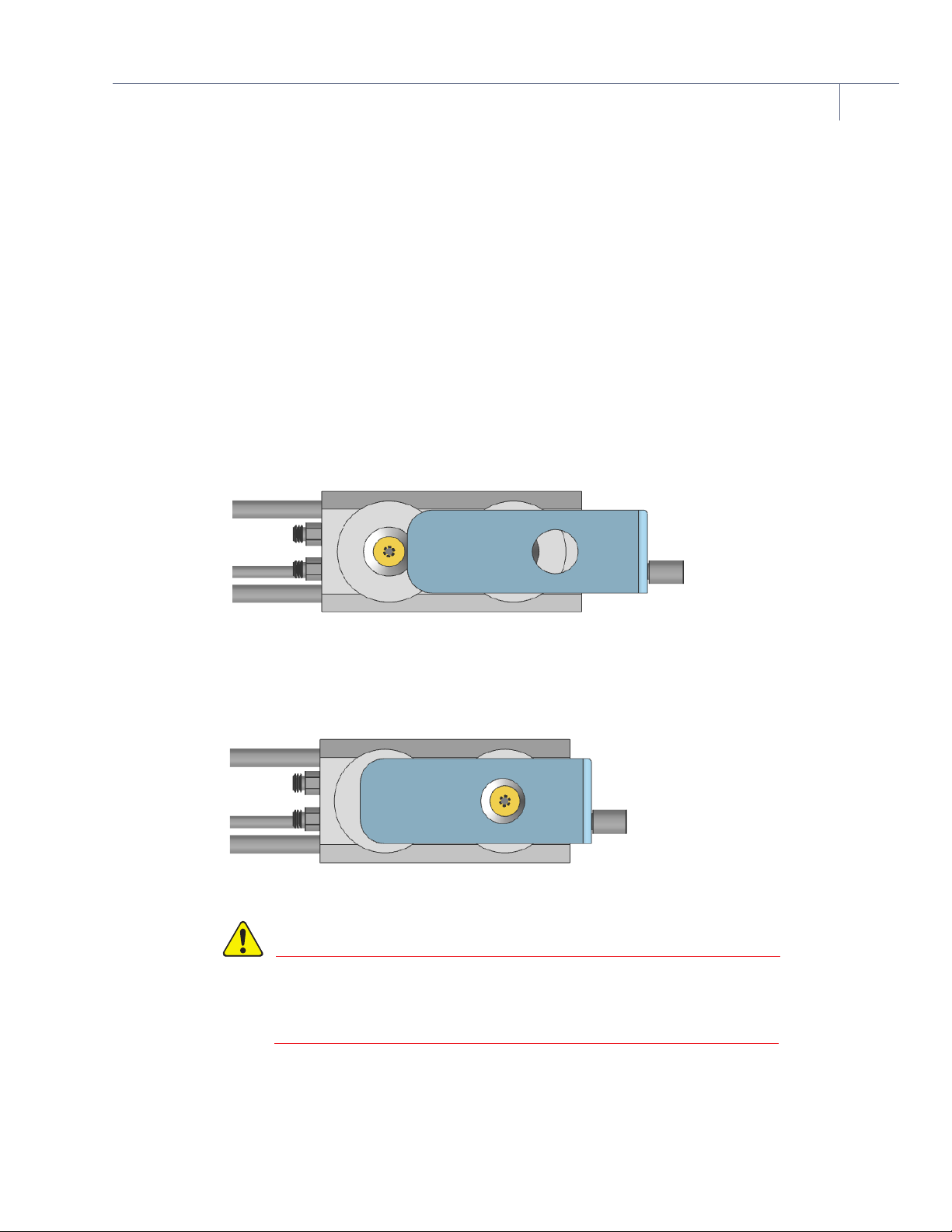
Crystal Leaf Spring
All Easy Rate Sensors have contact leafs that make the electrical connection from the
sensor to the rear electrode on the crystal. These contact leaves must be inspected
regularly. While rarely necessary, the spring contacts may need adjustment. Bend them
to a 45º angle as shown in Figure 6.
9 of 13
Easy Rate Sensor
PN 074-677-P1A
Figure 6 Contact leaf adjustment
Repair
Repairs to this sensor can be done in the field by an electrical technician at the risk and
responsibility of the sensor owner.
NOTE: Beyond the warranty period, this sensor is not serviced by INFICON.
WARNING
INFICON is not responsible for any damage or loss of property
that may occur during a sensor repair.
WARNING
Do not attempt to repair a sensor under warranty. Doing so will
void the warranty.
Electrical Test
If an issue with the sensor is suspected, first check the sensor assembly for continuity
and isolation. Measure continuity with a digital multimeter (DMM) capable of measuring
50 MΩ. Figure 7 shows the standard sensors. The same test can be applied to the right
angle sensor.
Continuity: <1 ΩFrom the microdot connector center pin to leaf spring center
Isolation: >50 MΩFrom the microdot connector center pin to the sensor body

10 of 13
Easy Rate Sensor
PN 074-677-P1A
Figure 7 Single and Dual Sensor Continuity and Isolation
Electrical Connection Repair
If the continuity test fails, the electrical connection will need to be replaced. For a dual
sensor, the steps below will need to be repeated for each crystal cavity. Images in these
instructions may be for one sensor, but the concept of the instruction is applicable to all
versions.
New items required:
Crystal Retainer Assembly Easy Rate Sensor . . . . . . . . . . PN 784-205-G1
Coax Connector Female Flat Sides . . . . . . . . . . . . . . . . . . PN 784-323-P1
Reusable items:
0-80 Retainer Plate Easy Rate Sensor . . . . . . . . . . . . . . . PN 784-322-P1
Screw 0-80 x 0.125 in. LG Slot Pan HD SS GP . . . . . . . . . PN 080-011-P3
Holder Finger Spring Easy Rate Sensor . . . . . . . . . . . . . . PN 784-405-P1
Crystal Holder Assembly Easy Rate Sensor . . . . . . . . . . . PN 784-204-G1
Items not provided by INFICON:
22 AWG, Buss Wire, Solid, Tin Coated Copper
Tubing, Teflon™, Clear, 0.066 inch OD
Kester 48 Core LF Solder
Continuity (<1 Ω)
Isolation (>50 MΩ)
Continuity (<1 Ω)
Isolation (>50 MΩ)

11 of 13
Easy Rate Sensor
PN 074-677-P1A
Tools: Soldering iron, adjustable wrench, Teflon™tweezers, torque screwdriver or
wrench
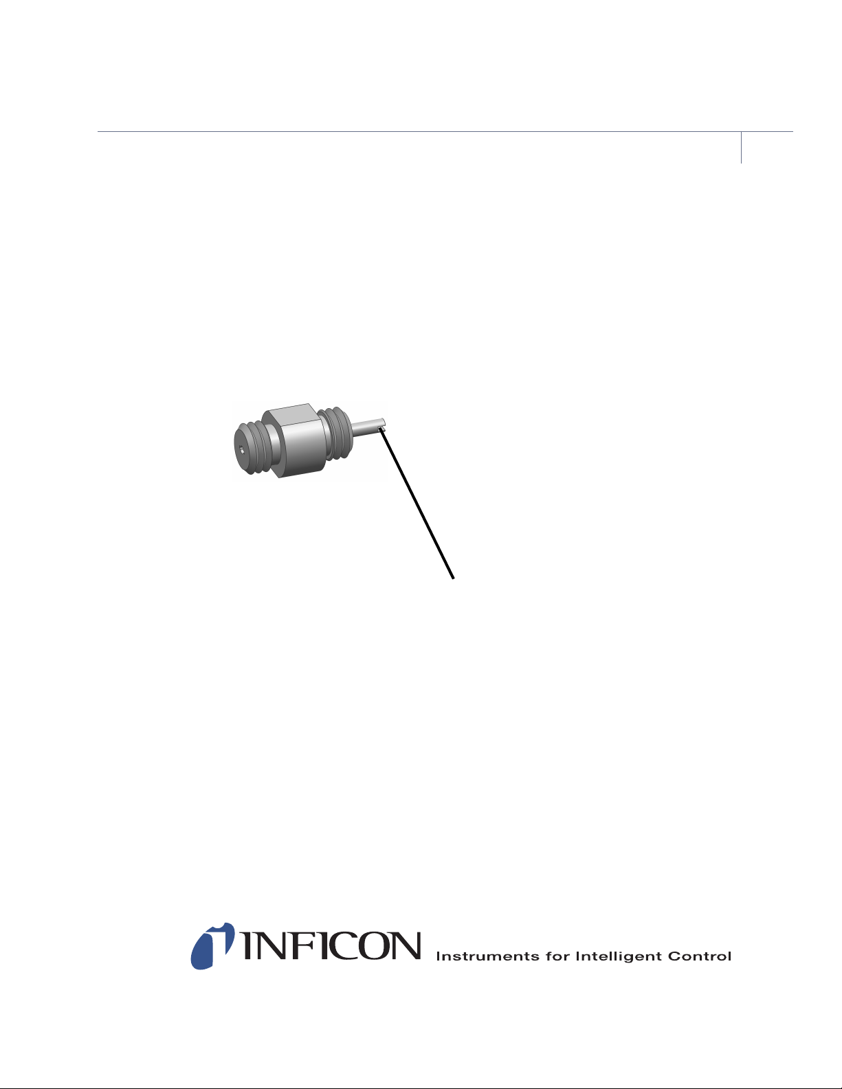
1Grasp the microdot connector by the flat sides using an adjustable wrench and
loosen it. (See Figure 8.)
Figure 8 Microdot connector
NOTE: If the wire inside is still intact, the connection will break as the connector
comes loose. This is normal and expected.
2Pull the crystal holder out of the sensor body. (See Figure 9.)
Figure 9 Remove crystal holder
12 of 13
Easy Rate Sensor
PN 074-677-P1A
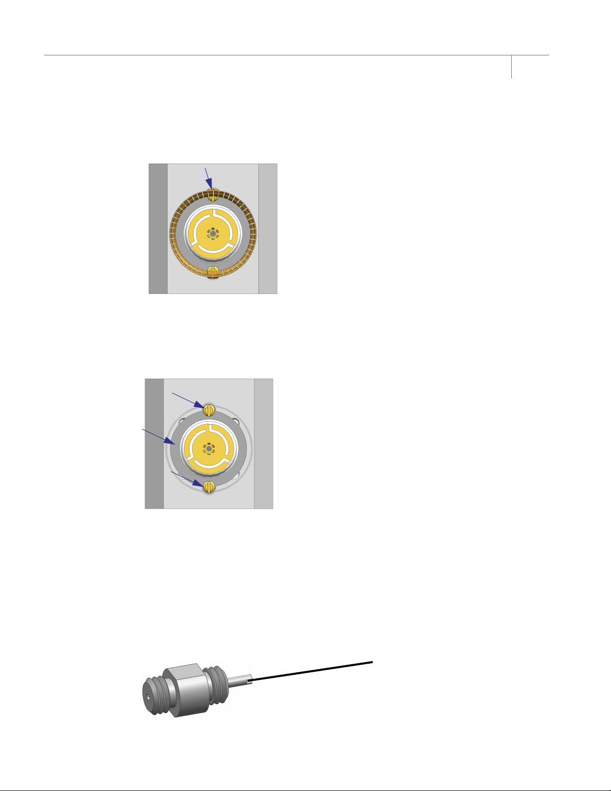
3Using Teflon™tweezers, gently pry the crystal holder spring out of the sensor body.
(See Figure 10.)
Figure 10 Crystal holder spring
NOTE: Move the spring circularly until the gap between the two ends is found and
pry it out from there.
4Loosen the two 0-80 screws and remove the 0-80 retainer plate. (See Figure 11.)
Figure 11 Loosen screws and retainer plate
5Pull the ceramic retainer assembly from the sensor body and inspect the cavity in the
sensor and components for debris or any possible contamination. If observed, clean
the sensor body and components.
6
Solder the wire onto the microdot connector. Prior to soldering, the wire end may need to
be crimped to fit the microdot slot.
For standard sensors, the wire should be soldered in parallel to the connector as
shown in Figure 12.
Figure 12 Standard sensor wire positioning
www.inficon.com [email protected]
Due to our continuing program of product improvements, specifications are subject to change without notice.
All trademarks are the property of their respective owners.
®
13 of 13
PN 074-677-P1A ©2018 INFICON
Easy Rate Sensor
For the standard single sensor, the wire can be soldered onto the microdot connector
prior to installation into the sensor. For the standard dual sensor, run the new
insulation into the sensor up to each crystal holder cavity followed by the connecting
wire, then solder the wire to the new microdot connector.
For right angle single and dual sensors, the wire should be soldered in perpendicular
to the connector as shown in Figure 13. This will help reduce the height of the solder
joint. To insert the connector into the sensor head, the wire will need to be
straightened.
Figure 13 Right angle single and dual sensor wire positioning
7Add the wire insulation over the wire. The insulation does not need to cover the
connector pin or solder joint. Trim any excess insulation, leaving some wire exposed.
8Thread the now wired connector onto the sensor body. Torque the connector to
1.7 N•m (240 oz•in).
9Install the ceramic retainer assembly into the cavity pushing the wire through the hole
in the center of the retainer.
10 Install the 0-80 plate and 0-80 screws to secure the ceramic retainer assembly.
11 Create a solder joint, joining the wire to the retainer, that is no taller than 0.11 cm
(0.045 in.). Trim any excess wire.
12 Perform continuity test once more.
13 Install the holder spring and crystal holder assembly to complete the repair.
This manual suits for next models
1
Table of contents
Other Inficon Accessories manuals


