Inficon LDS3000 AQ User manual

Typenbez.
Produktbeschreibung
Translation of the original operating instructions
Catalog no.
from software version
Document no.
560-300
MS-Module 2.41
jiqa54de1-04 (1512)
LDS3000
Mass spectrometer module

2
This document applies to the software version stated on the title page. Documents
for other software versions are available from our sales department.
Reprinting, translation, and duplication require written confirmation from INFICON
GmbH.

Content 3
Content
1 About these instructions . . . . . . . . . . . . . . . . . . . . . . . . . 6
1.1 Target groups . . . . . . . . . . . . . . . . . . . . . . . . . . . . . . . . . . . . . . . . . . . . 6
1.2 Other associated documents . . . . . . . . . . . . . . . . . . . . . . . . . . . . . . . . 6
1.3 Displaying information . . . . . . . . . . . . . . . . . . . . . . . . . . . . . . . . . . . . . 6
1.3.1 Warnings . . . . . . . . . . . . . . . . . . . . . . . . . . . . . . . . . . . . . . . . . 6
1.3.2 Text markings . . . . . . . . . . . . . . . . . . . . . . . . . . . . . . . . . . . . . 6
2 Safety . . . . . . . . . . . . . . . . . . . . . . . . . . . . . . . . . . . . . . . . . 8
2.1 Intended use . . . . . . . . . . . . . . . . . . . . . . . . . . . . . . . . . . . . . . . . . . . . . 8
2.2 Owner requirements . . . . . . . . . . . . . . . . . . . . . . . . . . . . . . . . . . . . . . . 8
2.3 Operator requirements . . . . . . . . . . . . . . . . . . . . . . . . . . . . . . . . . . . . . 9
2.4 General safety information . . . . . . . . . . . . . . . . . . . . . . . . . . . . . . . . . . 9
3 Shipment, Transport, Storage . . . . . . . . . . . . . . . . . . . . 11
4 Description . . . . . . . . . . . . . . . . . . . . . . . . . . . . . . . . . . . 12
4.1 Function . . . . . . . . . . . . . . . . . . . . . . . . . . . . . . . . . . . . . . . . . . . . . . . 12
4.2 Device setup . . . . . . . . . . . . . . . . . . . . . . . . . . . . . . . . . . . . . . . . . . . . 13
4.2.1 Overall device . . . . . . . . . . . . . . . . . . . . . . . . . . . . . . . . . . . . 13
4.2.2 Connection block . . . . . . . . . . . . . . . . . . . . . . . . . . . . . . . . . . 14
4.2.3 MSB box . . . . . . . . . . . . . . . . . . . . . . . . . . . . . . . . . . . . . . . . 14
4.3 Technical data . . . . . . . . . . . . . . . . . . . . . . . . . . . . . . . . . . . . . . . . . . 16
4.3.1 Mechanical data . . . . . . . . . . . . . . . . . . . . . . . . . . . . . . . . . . 16
4.3.2 Electrical data . . . . . . . . . . . . . . . . . . . . . . . . . . . . . . . . . . . . 16
4.3.3 Physical data . . . . . . . . . . . . . . . . . . . . . . . . . . . . . . . . . . . . . 16
4.3.4 Ambient conditions . . . . . . . . . . . . . . . . . . . . . . . . . . . . . . . . 17
4.3.5 Factory settings . . . . . . . . . . . . . . . . . . . . . . . . . . . . . . . . . . . 17
5 Installation . . . . . . . . . . . . . . . . . . . . . . . . . . . . . . . . . . . 19
5.1 Adjust the position of the connections to the installation dimensions . 19
5.2 Installing the mass spectrometer module on the test system . . . . . . . 20
5.3 Connecting the mass spectrometer module to the test system . . . . . 21
5.4 Establish component connection . . . . . . . . . . . . . . . . . . . . . . . . . . . . 22
5.5 Establish electrical connections . . . . . . . . . . . . . . . . . . . . . . . . . . . . . 23
6 Operation . . . . . . . . . . . . . . . . . . . . . . . . . . . . . . . . . . . . 24
6.1 Switching the unit on . . . . . . . . . . . . . . . . . . . . . . . . . . . . . . . . . . . . . . 24
6.2 Default settings . . . . . . . . . . . . . . . . . . . . . . . . . . . . . . . . . . . . . . . . . . 25

4Content
6.3 Selecting compatibility mode and operating mode . . . . . . . . . . . . . . . 25
6.4 Select gas type (mass) . . . . . . . . . . . . . . . . . . . . . . . . . . . . . . . . . . . . 27
6.5 Calibrating the device . . . . . . . . . . . . . . . . . . . . . . . . . . . . . . . . . . . . . 27
6.5.1 Internal calibration . . . . . . . . . . . . . . . . . . . . . . . . . . . . . . . . . 29
6.5.2 External calibration . . . . . . . . . . . . . . . . . . . . . . . . . . . . . . . . 30
6.5.3 External dynamic calibration . . . . . . . . . . . . . . . . . . . . . . . . . 32
6.5.4 External calibration with sniffer line SL3000XL (accessories) 34
6.5.5 Check the calibration . . . . . . . . . . . . . . . . . . . . . . . . . . . . . . . 34
6.5.6 Entering the calibration factor . . . . . . . . . . . . . . . . . . . . . . . . 36
6.5.7 Setting machine and sniff factor . . . . . . . . . . . . . . . . . . . . . . 36
6.6 Starting and stopping the measurement . . . . . . . . . . . . . . . . . . . . . . . 38
6.7 Loading and saving parameters . . . . . . . . . . . . . . . . . . . . . . . . . . . . . 38
6.8 Copying measurement data, deleting measurement data . . . . . . . . . 39
6.9 Suppressing gas backgrounds with "ZERO" functions . . . . . . . . . . . . 39
6.10 Measurement result display with signal filters . . . . . . . . . . . . . . . . . . . 40
6.11 Decontaminating the backing pump . . . . . . . . . . . . . . . . . . . . . . . . . . 41
6.12 Selecting a unit for the leak rate . . . . . . . . . . . . . . . . . . . . . . . . . . . . . 41
6.13 Select unit for pressure . . . . . . . . . . . . . . . . . . . . . . . . . . . . . . . . . . . . 42
6.14 Selecting display limits . . . . . . . . . . . . . . . . . . . . . . . . . . . . . . . . . . . . 42
6.15 Setting trigger values . . . . . . . . . . . . . . . . . . . . . . . . . . . . . . . . . . . . . 43
6.16 Setting capillary surveillance . . . . . . . . . . . . . . . . . . . . . . . . . . . . . . . . 43
6.17 Turbo molecular pump set-up . . . . . . . . . . . . . . . . . . . . . . . . . . . . . . . 43
6.18 Ion source set-up . . . . . . . . . . . . . . . . . . . . . . . . . . . . . . . . . . . . . . . . 44
6.19 Setting the preamplifier . . . . . . . . . . . . . . . . . . . . . . . . . . . . . . . . . . . . 45
6.20 Settings for the XL sniffer adapter . . . . . . . . . . . . . . . . . . . . . . . . . . . 46
6.21 Selecting the type of expansion module . . . . . . . . . . . . . . . . . . . . . . . 48
6.22 Settings for I/O module IO1000 . . . . . . . . . . . . . . . . . . . . . . . . . . . . . 48
6.22.1 General interface settings . . . . . . . . . . . . . . . . . . . . . . . . . . . 48
6.22.2 Assigning inputs and outputs . . . . . . . . . . . . . . . . . . . . . . . . . 49
6.23 Settings for bus module BM1000 . . . . . . . . . . . . . . . . . . . . . . . . . . . . 59
6.24 Warning and error messages . . . . . . . . . . . . . . . . . . . . . . . . . . . . . . . 59
6.24.1 Illustration of error codes with the help of the status LEDs . . 66
6.25 Resetting the settings . . . . . . . . . . . . . . . . . . . . . . . . . . . . . . . . . . . . . 66
7 Maintenance . . . . . . . . . . . . . . . . . . . . . . . . . . . . . . . . . . 67
7.1 Maintenance at INFICON . . . . . . . . . . . . . . . . . . . . . . . . . . . . . . . . . . 67
7.2 General maintenance information . . . . . . . . . . . . . . . . . . . . . . . . . . . . 67
7.3 Maintenance plan . . . . . . . . . . . . . . . . . . . . . . . . . . . . . . . . . . . . . . . . 68
7.4 Maintenance work . . . . . . . . . . . . . . . . . . . . . . . . . . . . . . . . . . . . . . . . 69
7.4.1 Change operating fluid reservoir of turbo molecular pump . . 69
8 Decommissioning the device . . . . . . . . . . . . . . . . . . . . 73
8.1 Shutting down the leak detector . . . . . . . . . . . . . . . . . . . . . . . . . . . . . 73
8.2 Disposing of the mass spectrometer module . . . . . . . . . . . . . . . . . . . 73
8.3 Returning the mass spectrometer module . . . . . . . . . . . . . . . . . . . . . 73


6About these instructions
1 About these instructions
1.1 Target groups
These operating instructions are intended for the owner and for technically qualified
personnel with experience in leak detection technology and integration of leak detec-
tion devices in leak detection systems. In addition, the installation and use of the unit
require knowledge of electronic interfaces.
1.2 Other associated documents
1.3 Displaying information
1.3.1 Warnings
1.3.2 Text markings
Operating Manual Control Unit CU1000 jina54
Operating instructions bus module jiqb10
Operating instructions I/O module jiqc10
Operating instructions XL sniffer adapter jinxa54
Interface protocols jira54
Imminent threat resulting in death or serious injuries
Hazardous situation resulting in potential death or serious injuries
Hazardous situation resulting in minor injuries
Hazardous situation resulting in damage to property or the environment
Marking Meaning
Requirement for execution of an action
Tool or aid for an action

About these instructions 7
►Instruction
1, 2, 3, ... Several instructions in a fixed order
Result of an action
Marking Meaning

8Safety
2Safety
2.1 Intended use
The unit is a modular leak detector for installation in industrial leak detection sys-
tems. The test gases that can be measured with the unit are helium and hydrogen
(forming gas).
The unit is suitable for pressure and vacuum testing. The unit is used for integral test-
ing in a vacuum and for local testing with a sniffer line.
►You must install, operate and service the device only in compliance with these op-
erating instructions.
►Adhere to the restrictions of use (see chapter 4.3, page 16 ).
Unauthorized use ►Do not suck up liquids with the device.
►Avoid the following, non-intended uses of the turbo molecular pump:
– Pumping corrosive of explosive media,
– Pumping condensing steam or fumes,
– Operation with excessive gas loads,
– Operation with excessive foreline pressure,
– Operation in incorrect gas mode,
– Operation with an excessive irradiated heat output,
– Flushing with excessive flushing rate,
– Usage of the device in radioactive areas,
– Usage of the pumps in plants where sudden loads and vibrations or periodic
forces act upon the pump.
2.2 Owner requirements
Safety conscious operation
►Operate and install the unit only in technically perfect working order and as spec-
ified, in a safety-conscious and hazard-conscious manner and in compliance with
these instructions.
►Fulfill and ensure compliance with the following regulations:
– Intended use
– Universally valid safety and accident prevention regulations
– International, national and local standards and guidelines
– Additional device-related provisions and regulations
►Use only original parts or parts approved by the manufacturer.
►Keep this manual available at the operating site.

Safety 9
Personnel qualifications
►All work must be performed only by technically qualified specialists who have
been trained on the unit.
►Allow personnel in training to work on the unit only under the supervision of tech-
nically qualified specialists.
►Make sure that the authorized personnel have read and understood these instruc-
tions and all other applicable documents (see chapter 1.2, page 6), especially the
information on safety, maintenance and repairs, before starting work.
►Define responsibilities, authorizations and supervision of personnel.
2.3 Operator requirements
►Read, observe and follow the information in these instructions and the working in-
structions created by the owner, especially the safety instructions and warnings.
2.4 General safety information
The device was built according to the state of the art and the recognized safety reg-
ulations. Nevertheless, improper use may result in risk to life and limb on the part of
the user or third parties, or damage to the unit or other property may occur.
Electric power
The device is operated with electrical voltages of up to 24 V. Inside the unit there are
voltages that are considerably higher. Touching parts where electrical voltage is
present can result in death.
►Disconnect the unit from the power supply prior to any installation and mainte-
nance work.
Touching live parts with the sniffer probe can result in death.
►Before starting the leak test, disconnect electrically operated test objects from the
power supply.
The device contains electric components that can be damaged from high electric
voltage.
►Before connecting the unit to the power supply, make sure that the supply voltage
is 24V+/-10%.
Liquids and chemical substances
Liquids and chemical substances can damage the device.
►Comply with the limits of application (see chapter 4.3, page 16).
►Do not suck up liquids with the device.
►Keep the hydrogen concentration below 5 % to prevent ignition.
Permanent magnets
Permanent magnets in the unit pose a hazard to health.
►Keep a sufficient distance from the unit.

10 Safety
Kinetic energy
If the rotating parts in the turbo molecular pump are blocked because of some dam-
age, high centrifugal forces must be absorbed. If this is not successful, the mass
spectrometer module will breakaway and possibly cause damage to property or per-
sonal injury.
►Make sure the mount of the mass spectrometer module is able to absorb a brak-
ing torque of 670 Nm.
Interference with pacemakers
The magnets in the mass spectrometer module can affect the proper functioning of
pacemakers.
►Always comply with the distances recommended by the pacemaker manufactur-
er without fail.
Shipment, Transport, Storage 11
3 Shipment, Transport, Storage
Shipment
►Please check the scope of delivery of the LDS3000 for completeness after re-
ceipt.
Transport
Storage ►Always store the device in compliance with the technical data, see chapter 4.3,
page 16.
Item Quantity
Mass spectrometer module 1
Plug for 24V connection 1
Pressure sensor PSG500 1
Self-locking nuts 4
Plug for Output 1
Plug for Gauges Exit 1
operating instructions 1
USB flash-drive with instructions, 3D drawings and videos 1
Damage due to unsuitable packaging material
Transport in unsuitable packaging material can damage the device.
►Transport the unit only in the original packaging material.
►Keep original packaging material.
Damage from incomplete MO bearings
►Fix MO bearing in place with the shipping screw.

12 Description
4 Description
4.1 Function
The mass spectrometer module is a detection device for the test gases helium and
hydrogen. Integrated in test systems, the unit is used to detect gas being emitted
from a test object in order to indicate leaks.
The unit can be used both as a vacuum leak detector and a sniffer leak detector.
Sniffer lines with different lengths are available for the sniffer mode.
The MSB box outputs data on digital interfaces to the control unit CU1000, I/O mod-
ule IO1000 or bus module BM1000.
The mass spectrometer module is part of the leak detection system LDS3000. Es
can be operated in a test system together with a bus module or I/O module and a
data cable without additional INFICON accessories.
With the available accessories XL sniffer adapter and sniffer line SL3000XL, it is pos-
sible to capture leaks at a larger distance from the expected leak if the detection limit
is deteriorated (operation in "high flow" mode).
Description 13
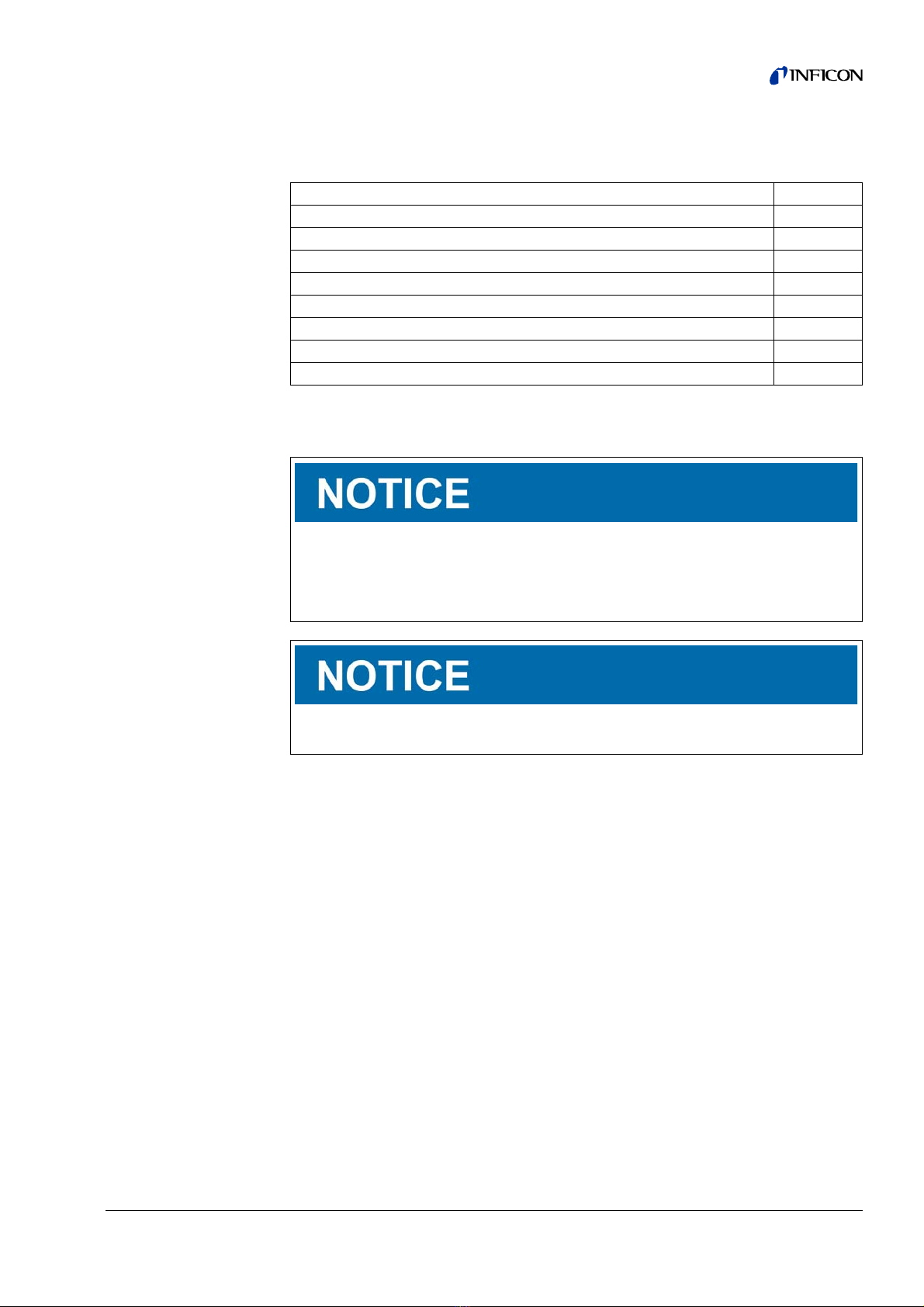
4.2 Device setup
4.2.1 Overall device
a. Connection block. Connections for test system, backing pump, pressure sensor
PSG500, internal calibration leak and sniffer line, see also Fig. 2.
b. Pressure sensor PSG500 for measuring the pressure of the backing pump
c. Turbo molecular pump with cooling unit
d. Preamplifier of the mass spectrometer module
e. MSB box. Interfaces of the mass spectrometer module (see chapter 4.2.3,
page 14)
f. Inverter for turbo molecular pump
g. Electronic controller of the turbo molecular pump
h. Fasteners for installing the mass spectrometer module in a test system
i. Rating plate containing mass spectrometer module specifications
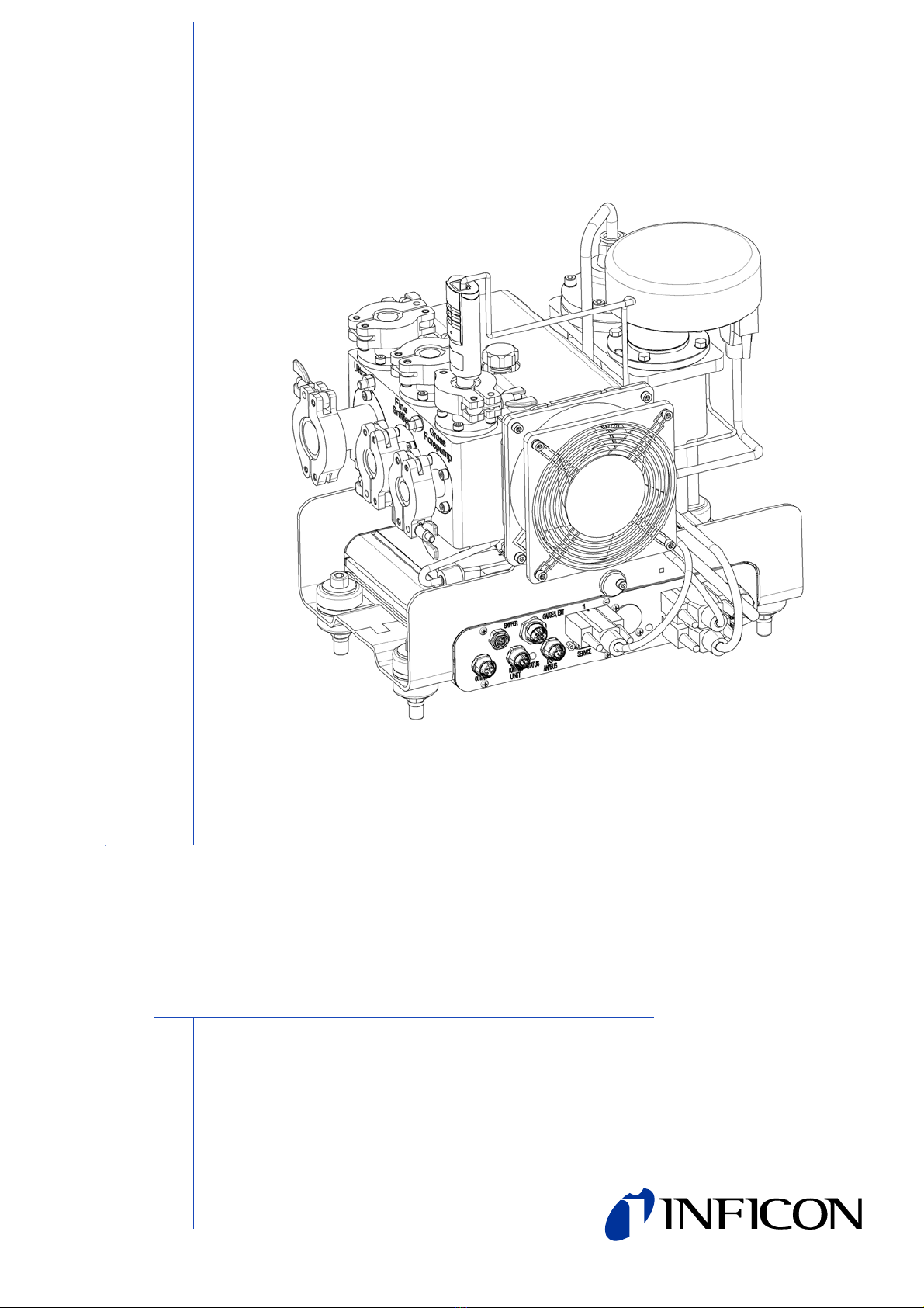
Fig. 1 Mass spectrometer module LDS3000
‚ƒ„†‡…ˆ

14 Description
4.2.2 Connection block
aConnection Ultra
bConnection Fine/Sniffer
cConnection Gross/Forepump
4.2.3 MSB box
OUTPUT
Connection for gas ballast and three valves
Connection plug arrangement
Fig. 2 Connection block
abc
Fig. 3 MSB box connections
SNIFFERGAUGES, EXT1SERVICEOUTPUTCONTROLUNITSTATUSI/OANYBUS24VDC23ION SOURCE
1 Valve 2 (gas ballast), 24 V, max.1 A
2 Valve 3 (not used, reserve)
3 Valve 4 (not used, reserve)
4 Valve 6 (not used, reserve)
5GND
Description 15
SNIFFER
Electrical connection for the sniffer line
GAUGES, EXT
Connection for optional external service gauges (0°... 10 V/0 … 20 mA) for
INFICON Service
1
Connection for pressure sensor PSG500, calibration leak and suppressor on the pre-
amplifier (premounted, three-core cable)
24VDC
Connection for 24 V power supply pack used to supply mass spectrometer module,
control unit, I/O module and bus module.
2
Connection for inverter turbo molecular pump and fan turbo molecular pump (pre-
mounted, two-core cable)
ION SOURCE
Connection for ion source
3
Connection for preamplifier
Power LED / Status LED
The Power LED and Status LED indicate the status of the device.
Connection plug arrangement
1 +24-V-Output, max. 200 mA
2 Input for P3 service gauge, 0 ... 10 V
3GND
4 Reference to input for P3 service gauge
5 20 mA input for P3 service gauge
Power LED Status LED Meaning
Off Red Device not ready for operation
Green Blue Turbo molecular pump is starting
Green Orange Emission is switched on
Green Green Emission is stable
Green Violet Speed of the turbo molecular pump is
not within the normal range
Green Error codes of the
status LED
Different activities of the unit
Green, flashes slow-
ly
Supply voltage < 21.6 V
Green, flashes fast Supply voltage > 26.4 V
Green, flashes Off Software is being updated
Green Green, flashes Software is being updated

16 Description
SERVICE
RS232 connection for INFICON Service
I/O / ANYBUS
CONTROL UNIT
Connection for I/O or bus module or control unit
The connections "I/O Anybus" and "Control Unit" have the same functions. You have
the choice of connecting:
– Control unit CU1000 + I/O module IO1000
– Control unit CU1000 + bus module BM1000
STATUS
Status LED
The Power LED and Status LED indicate the status of the unit.
4.3 Technical data
4.3.1 Mechanical data
4.3.2 Electrical data
4.3.3 Physical data
Dimensions (W x H x D) 320 mm x 280 mm x 240 mm
Weight 14.3 kg
Connection Gross/Forepump 2 x DN 16
Connection Fine/Sniffer 2 x DN 16
Connection Ultra DN 16 and DN 25
Supply voltage 24 V ± 10% DC
Power input max. 10 A
Connection line cross section
< 7 m length
< 11.9 m length
< 19 m length
1.5 mm2
2.5 mm2
4.0 mm2
Noise level < 60 dB(A)
Detectable gases 4He, H2, Mass 3 (e.g. H-D, 3He or H3)
Max. inlet pressure
(varying with the operation mode and
the speed of the turbo molecular
pump)
0.2 mbar ... 18 mbar
Operation in vacuum mode
Minimum detectable leak rate helium
(depending on the rotational speed of
the turbo molecular pump):
5x10
-12 mbar l/s
Time until ready for operation 150 s
Description 17
4.3.4 Ambient conditions
4.3.5 Factory settings
Operation in Sniffer mode
Minimum detectable leak rate helium
(depending on the rotational speed of
the turbo molecular pump):
1x10
-7 mbar l/s
Response time in Sniffer mode Gross: < 5 s, Fine/Ultra: < 1 s
Permissible ambient temperature
(during operation)
10 °C ... 45 °C
Permissible storage temperature -20 °C ... 60 °C
Max. relative humidity up to 31 °C 80%
Max. relative humidity from 31 °C to 40 °C linearly decreasing from
80% to 50%
Max. relative humidity above 40 °C 50%
Protection class IP40
Pollution degree II
Max. altitude above sea level 2000 m
Max. induction 7 mT
Parameters Factory setting
AO upper limit exp. 1 x 10⁻⁵
Operation mode Vacuum
Bus module address 126
Pressure capillary surveillance clogged
– with XL sniffer adapter (low flow)
0.4 mbar
0.2 mbar
Pressure capillary surveillance broken
– with XL sniffer adapter (low flow)
2 mbar
0.6 mbar
Pressure capillary surveillance clogged
– with XL sniffer adapter (high flow) 150 mbar
Pressure capillary surveillance broken
– with XL sniffer adapter (high flow) 400 mbar
Pressure unit (interface) mbar
Emission On
Filter leak rate threshold 1 x 10⁻¹⁰
Filter ZERO time 5 s
Filter mode I•CAL
Gas percentage H2 (M3, He) 100 %
Gas ballast Off
I/O module protocol ASCII
Calibration request On
Calibration factor VAC/SNIF Mx
(for vacuum, sniffer and all masses)
1.0
Cathode selection Auto Cat1
Compatibility mode LDS3000

18 Description
Config. Analog output 1 Leak rate mantissa
Config. Analog output 2 Leak rate exponent
Config. Analog output scale 0.5 V / decade
Configuration of digital outputs Pin 1: Trigger 1, inverted
Pin 2: Trigger 2, inverted
Pin 3: Trigger 3, inverted
Pin 4: Trigger 4, inverted
Pin 5: Ready
Pin 6: Error, inverted
Pin 7: CAL request, inverted
Pin 8: Open, inverted
Configuration of digital Inputs Pin 1: Select dyn. / normal CAL
Pin 2: Sniff
Pin 3: Start/Stop, inverted
Pin 4: ZERO
Pin 5: External CAL
Pin 6: Internal CAL
Pin 7: Clear
Pin 8: ZERO update
Pin 9: –
Pin 10: –
Leak rate unit SNIF, (display and interface) mbar l/s
Leak rate unit VAC, (display and interface) mbar l/s
Leak rate upper limit VAC (interface) 1.0 x 10⁴
Leak rate lower limit VAC (interface) 1.0 x 10⁻¹²
Leak rate upper limit SNIF (interface) 1.0 x 10⁴
Leak rate lower limit SNIF (interface) 1.0 x 10⁻⁸
Fan mode Fan always on
Machine factor in standby Off
Machine factor / Sniff factor 1.0 (for all masses)
Mass 4
Module on the I/O connection IO1000
Nominal state TMP On
calibration leak external SNIF 9.9 x 10⁻²
calibration leak external VAC 9.9 x 10⁻²
calibration leak internal 9.9 x 10⁻²
Open calibration leak internal Off
Sniffer line detection On
Sniffer key ZERO On
Language English
TMP rotational speed 1500
Trigger level 1 (2, 3, 4) 1 x 10⁻⁵ mbar l/s
Preamplifier test at CAL On
Maintenance warning Off
ZERO with start Off
ZERO mode Suppress everything
Parameters Factory setting
Installation 19
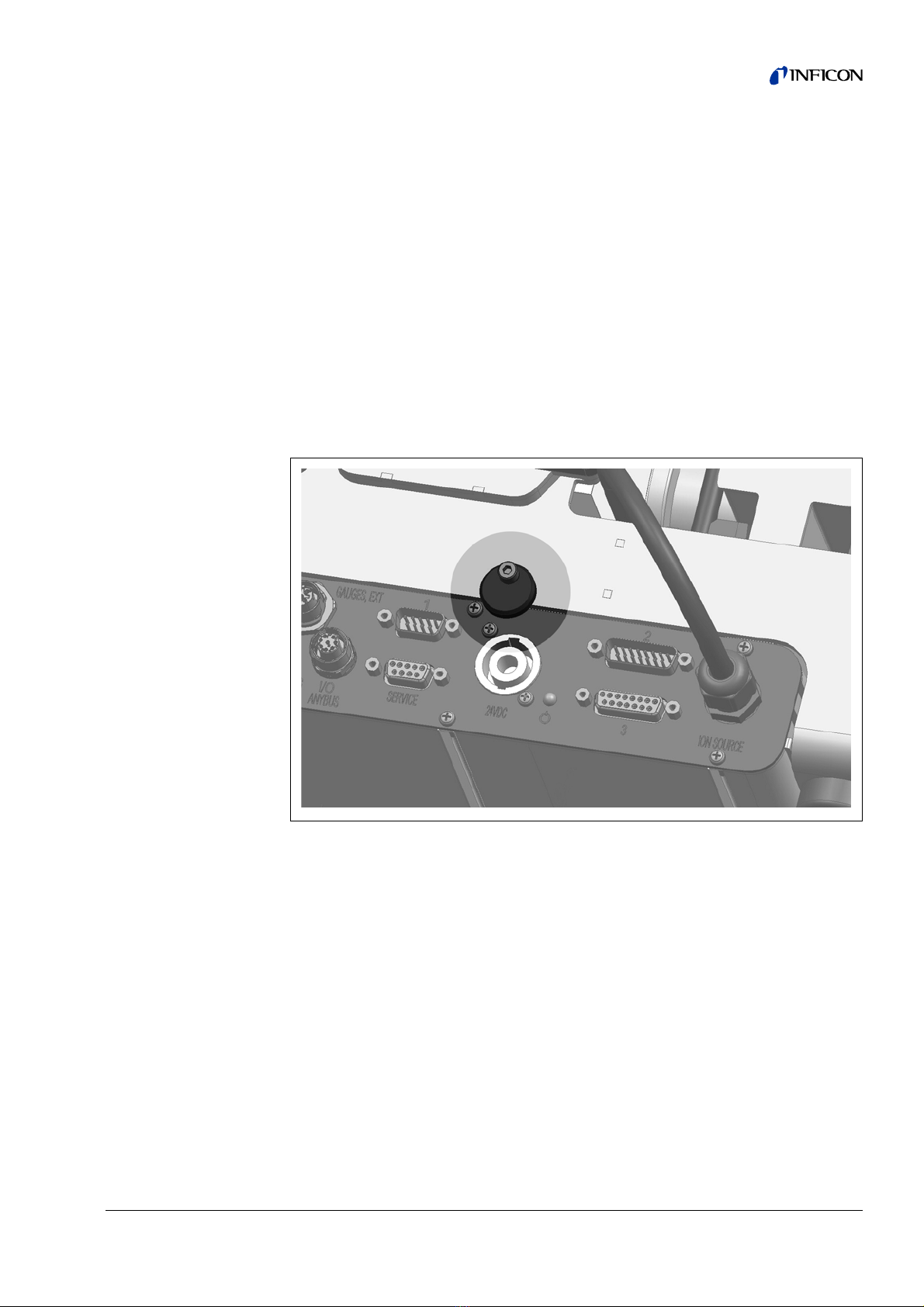
5 Installation
5.1 Adjust the position of the connections to the installation di-
mensions
In order to ideally match the installation position space, the MSB box can be turned
and rotated.
The MSB box is seated in two guide rails and can be pushed into the housing from
the left or from the right. It can also be rotated, if necessary, so that the labels are
upside down.
The locking washer must be released to pull out the MSB box.
If the MSB box is to be pushed into housing from the other side, the locking washer
must also be tightened on the other side of the housing. An appropriate threaded
hole is available.
Fig. 4 Lock
Other manuals for LDS3000 AQ
2
Table of contents
Other Inficon Control Unit manuals


Popular Control Unit manuals by other brands


VAT
VAT 650 Series Installation, operating, & maintenance instructions

Lunos
Lunos Touch Air Comfort Technical Information Sheet

National Instruments
National Instruments PXI Terminal Block NI TB-2708 installation guide

Libre
Libre LS6-N22S user manual

Dembla
Dembla GTV - 01 Series Installation operation & maintenance

Monmouth Scientific
Monmouth Scientific CAM-F 1500 operating & maintenance manual