Infinera XTM Series Parts list manual

XTM Series
TM-3000
Technical Description
TM-3000 DC, 19"/ETSI/23"(TM3000-DC)
TD-TM3000
Rev U | 2018-06-24

Copyright
© Copyright 2018 Infinera Corporation. All rights reserved.
This Manual is the property of Infinera Corporation and is confidential. No part of this Manual may be reproduced for
any purposes or transmitted in any form to any third party without the express written consent of Infinera.
Infinera makes no warranties or representations, expressed or implied, of any kind relative to the information or any
portion thereof contained in this Manual or its adaptation or use, and assumes no responsibility or liability of any kind,
including, but not limited to, indirect, special, consequential or incidental damages, (1) for any errors or inaccuracies
contained in the information or (2) arising from the adaptation or use of the information or any portion thereof
including any application of software referenced or utilized in the Manual. The information in this Manual is subject to
change without notice.
Trademarks
Infinera, Infinera Intelligent Transport Networks, I-PIC, IQ NOS, FlexILS, DTN-X, DTN, ATN, FastSMP and logos that
contain Infinera are trademarks or registered trademarks of Infinera Corporation in the United States and other
countries. All other trademarks in this Manual are the property of their respective owners.
Infinera DTN-X, DTN, FlexILS, Cloud Xpress, XT and ATN Regulatory Compliance
FCC Class A
This device complies with Part 15 of the FCC rules. Operation is subject to the following two conditions: (1) this
device may not cause harmful interference, and (2) this device must accept any interference received, including
interference that may cause undesired operation. Modifying the equipment without Infinera's written authorization
may result in the equipment no longer complying with FCC requirements for Class A digital devices. In that event,
your right to use the equipment may be limited by FCC regulations, and you may be required to correct any
interference to radio or television communications at your own expense.
DOC Class A
This digital apparatus does not exceed the Class A limits for radio noise emissions from digital apparatus as set out in
the interference-causing equipment standard titled “Digital Apparatus," ICES-003 of the Department of
Communications.
Cet appareil numérique respecte les limites de bruits radioélectriques applicables aux appareils numériques de
Classe A prescrites dans la norme sur le matériel brouilleur: "Appareils Numériques," NMB-003 édictée par le
Ministère des Communications.
Class A ITE
This is a Class A product based on the standard of the VCCI Council. If this equipment is used in a domestic
environment, radio interference may occur, in which case, the user may be required to take corrective actions.
Warning
This is a class A product. In a domestic environment this product may cause radio interference in which case the user
may be required to take adequate measures.
FDA
This product complies with the DHHS Rules 21CFR 1040.10 and 1040.11, except for deviations pursuant to Laser
Notice No. 50,dated June 24, 2007.

Technical Assistance
Customer Support for Infinera products is available, 24 hours a day, 7 days a week (24x7).
For information or assistance with Infinera products, please contact the Infinera Technical
Assistance Center (TAC) using any of the methods listed below:
• Telephone:
• Direct within United States: 1-408-572-5288
• Outside North America: +1-408-572-5288
• Toll-free within United States: +1-877-INF-5288 (+1-877-463-5288)
• Toll-free within Germany/France/Benelux/United Kingdom: 00-800-4634-6372
• Toll-free within Japan: 010-800-4634-6372
• Infinera corporate website: http://www.infinera.com
• Infinera Customer Web Portal: https://support.infinera.com
Please see the Infinera Customer Web Portal to view technical support policies and
procedures, to download software updates and product documentation, to view training
course information, or to create/update incident reports and RMA requests.
Documentation Feedback
Infinera strives to constantly improve the quality of its products and documentation. Please
submit comments or suggestions regarding Infinera Technical Product Documentation using
any of the following methods:
• Submit a service request using the Infinera Customer Web Portal
• Send mail to the following address:
Attention: Infinera Technical Documentation and Technical Training
Infinera Corporation
140 Caspian Court
Sunnyvale, CA 94089
When submitting comments, please include the following information:
• Document name and document ID written on the document cover page
• Document release number and version written on the document cover page
• Page number(s) in the document on which there are comments

TD-TM3000 Rev U | 2018-06-24 IV
Infinera Proprietary and Confidential
CONTENTS
Contents
1 Introduction.........................................................................................................................1
1.1 Document Revision History.........................................................................................1
2 Functional Description .........................................................................................................2
2.1 Introduction ...............................................................................................................2
2.2 Basic configuration.....................................................................................................3
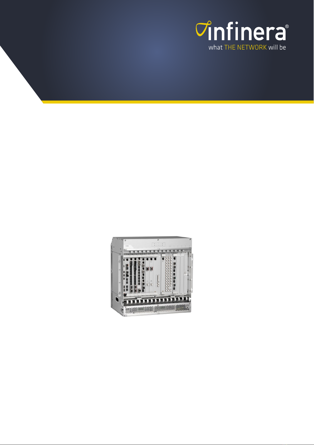
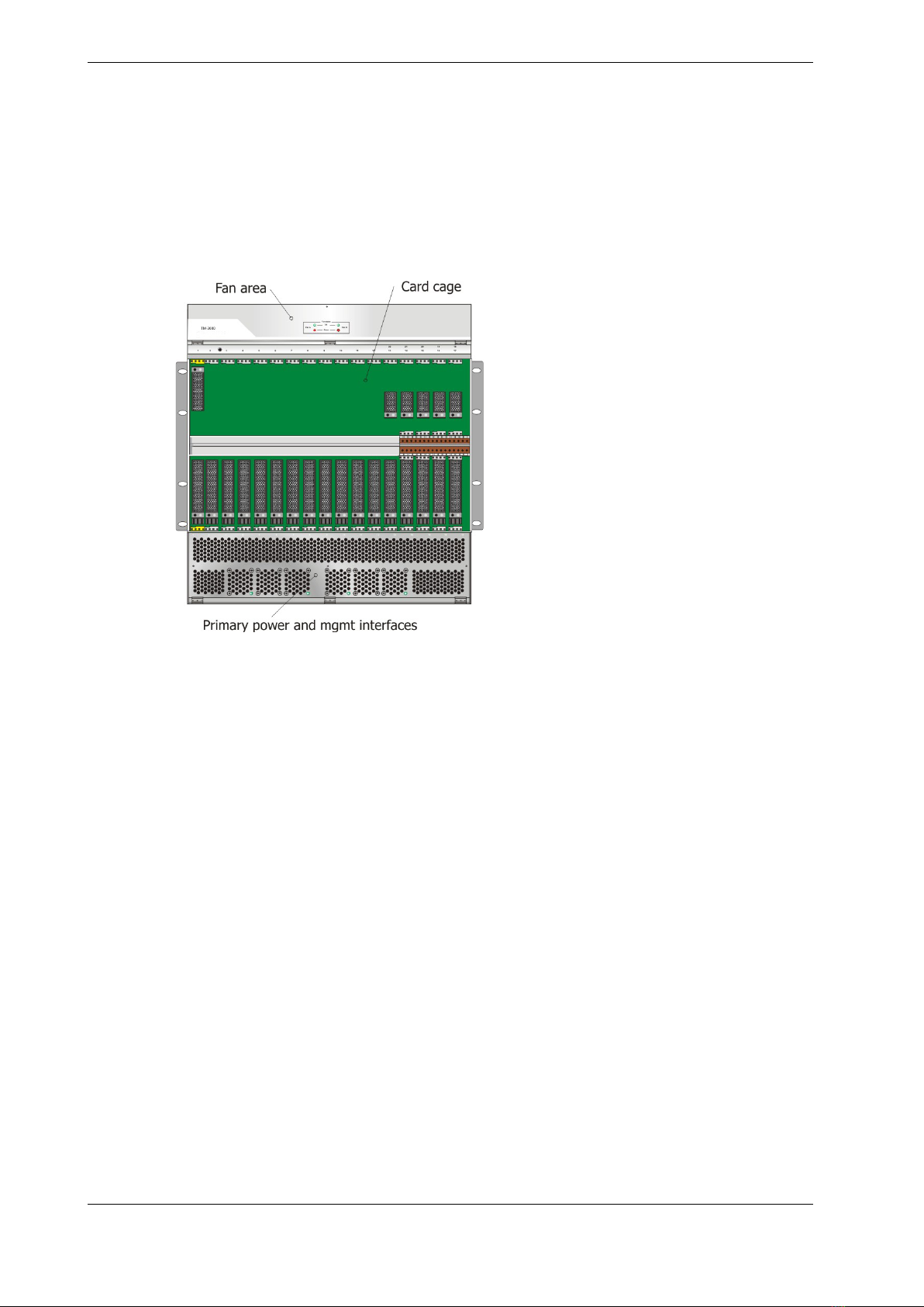
2.3 TM-3000 Chassis.......................................................................................................4
2.4 Rack Mount...............................................................................................................4
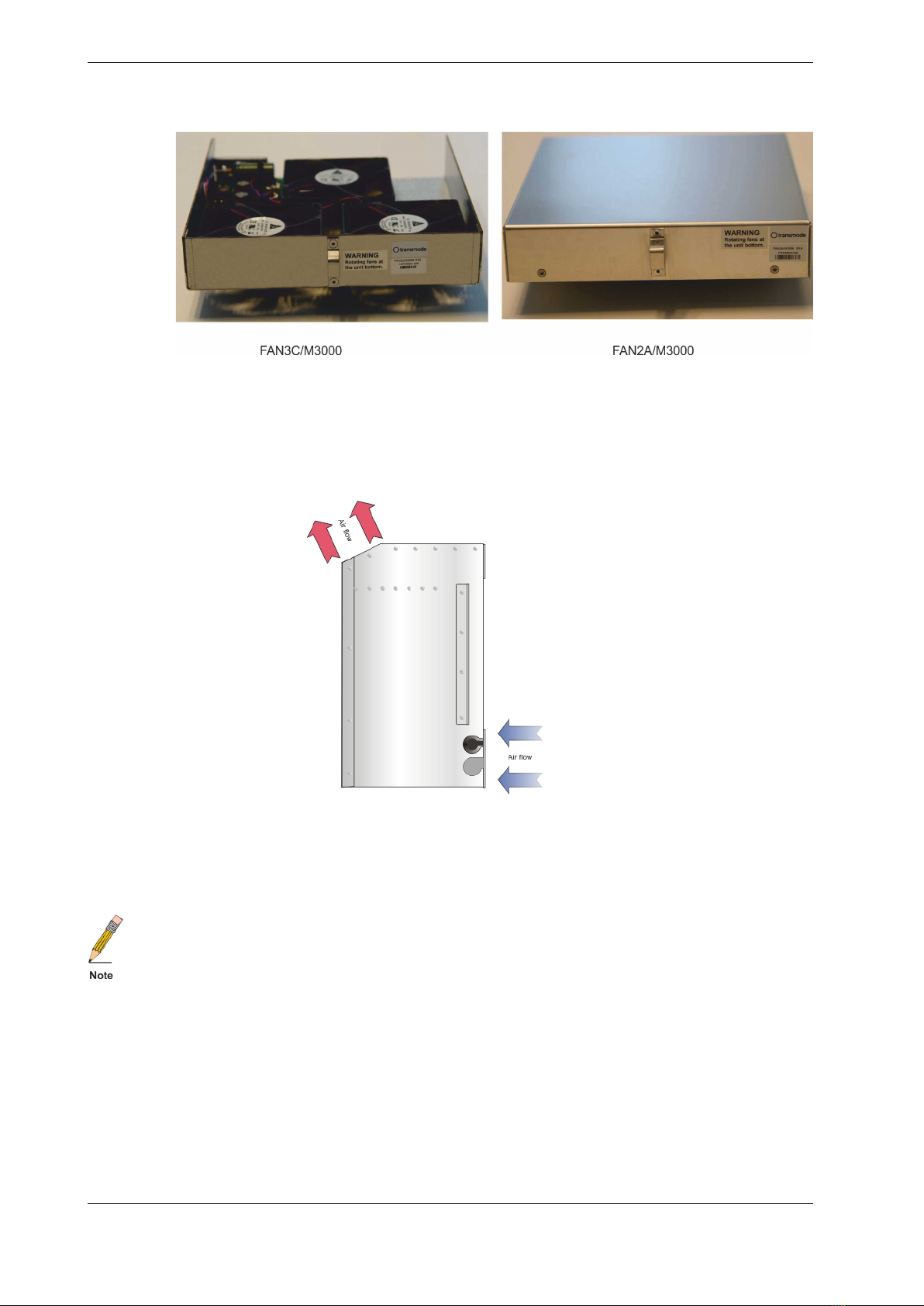
2.5 Fan Units ..................................................................................................................5
2.6 Air Filter ....................................................................................................................7
2.7 Primary power alternatives .........................................................................................8
2.7.1 DC-Power........................................................................................................8
2.7.2 AC-Power......................................................................................................10
2.8 External Interfaces...................................................................................................12
2.9 Card Cage...............................................................................................................14
2.10 Chassis Identity .....................................................................................................15
2.11 Sys mode ..............................................................................................................15
2.12 Fiber management.................................................................................................16
2.13 Fiber management shelf .........................................................................................17
2.14 Board extraction handle..........................................................................................17
2.15 External Alarms .....................................................................................................18
3 Configuration Guidelines....................................................................................................20
3.1 DC-filters and card cage power consumption .............................................................21
3.2 AC/DC converters and DC-filters...............................................................................22
3.3 Required fan units for high power units in TM-3000 ....................................................23
3.4 Power consumption .................................................................................................25
3.4.1 Chassis of R-states R1 – R3............................................................................25
3.4.2 Chassis of R-states R4 – R5............................................................................25
3.5 Card cage guidelines TM-3000 .................................................................................26
3.6 Plug-in units in TM-3000 ..........................................................................................28
3.7 CU compatibility.......................................................................................................33
3.7.1 HW and SW compatibility................................................................................37
3.7.2 Master-Slave compatibility ..............................................................................38
4 Chassis revision updates ...................................................................................................39
4.1 R1C Updates...........................................................................................................39
4.2 R2 Updates .............................................................................................................39
4.3 R3 Updates .............................................................................................................40
4.4 R4 updates..............................................................................................................42
4.4.1 Release R15 updates .....................................................................................43
4.5 R5 Updates .............................................................................................................43
4.6 Board Extraction Tool ...............................................................................................45
5 Labels ..............................................................................................................................46
6 Technical Data ..................................................................................................................48
6.1 Environmental conditions .........................................................................................49
6.2 Mechanical drawing .................................................................................................51
6.3 Revision Data..........................................................................................................52
6.4 Ordering Data..........................................................................................................53
6.4.1 Spare Parts....................................................................................................55
7 Appendix: Example Configurations .....................................................................................56
7.1 40x 10GbE TM-3000/TM-3000/II System Example .....................................................56
7.2 80x 10Gb/s TM-3000/TM-3000/II Example.................................................................57

TD-TM3000 Rev U | 2018-06-24 1 (60)
Infinera Proprietary and Confidential
1 Introduction
This manual provides an overview of the TM-3000 chassis.
1.1 Document Revision History
Table 1 Document Revision History
Revision Date Description of changes
A 2012-02-22 Due to introduction of a new documentation tool, the revision is reset to A. For details
on previous document changes/updates, please see corresponding document in Sys-
tem Manual release R18.
The following is added compared to the R18 version:
- Information about R5 chassis.
- Information on new fan unit.
- Updated/improved information on the External Alarms unit function.
B 2012-08-16 Updated/improved chapter on supported plug-in units.
Updated/improved chapter on fan unit support.
Updated/improved chassis size figure.
C 2012-12-16 Chapter in supported plug-in units reduced to cover only TM-3000 & TM-3000/II
chassis.
Updated examples in Appendix.
D 2013-02-09 Corrected slot numbers for passive MDU8 units in chapter 4.
E 2013-03-04 Added information on cable lengths (AC and DC cabling).
Editorial changes.
F 2013-06-12 R21 updates:
- Plug-in unit support list updated.
- Addition of fan unit support matrix.
- Addition of chapter on fiber management shelf.
- Corrected DC cable dimension in table 5
G 2013-11-12 - General improvements.
- Plug-in unit support list updated to reflect R22 status.
- Addition of Appendix covering required fan units.
- Addition of chapter covering fiber management.
- Addition of chapter covering CU and TU compatibility.
- Improved description of card cage restrictions.
- Updated example configuration chapter.
H 2014-05-12 Updates to reflect R23 status
I 2014-09-12 Updated to reflect R23.1 status
Improved descriptions on required fan units and capabilities using different DC-filters
J 2014-12-20 Updates to reflect R24.0: Change of SW name in chapter with plug-in unit compatibility.
K 2014-06-01 Updates to reflect R25.0. Added chapter on power consumption for different chassis
configurations.
L 2015-12-10 Editorial changes, Infinera branding.
L1 2015-12-28 Corrected revision of chassis in 6 Technical Data.
M 2016-03-16 Updates to reflect R26.1: Change of SW name in chapter with plug-in unit compatibility.
N 2016-06-20 Updates to reflect R27.0: Change of SW name in chapter with plug-in unit compatibility.
O 2016-12-20 Updates to reflect R28.0: Addition of new supported plug-in units.
P 2017-04-20 Updates to reflect R28.1.
Q 2017-06-20 Updates to reflect R29.0. Added information on extraction handle that is introduced on
new/selected boards.
R 2017-09-20 Updates to reflect R29.1.
S 2017-12-15 Updates to reflect R30.0.
T 2018-04-15 Updates to reflect R30.1 (only release reference changes).
U 2018-06-24 Updates to reflect R31.0
INTRODUCTION

TD-TM3000 Rev U | 2018-06-24 2 (60)
Infinera Proprietary and Confidential
2 Functional Description
2.1 Introduction
The TM-3000 chassis is no longer orderable. It is replaced by the more recent TM-3000/II
chassis. The information in this document is for reference only. Spare parts are still available.
The TM-3000 chassis is the largest chassis alternative in the XTM Series. The TM-3000 chas-
sis has a passive backplane, i.e. no traffic is transported over this interface. This gives a high
level of flexibility since there are no dedicated slots (apart for the Control Unit) for certain
board types.
The generic backplane enables a TM-3000 chassis to be configured as a multi-purpose Net-
work Element (NE). As an example, a TM-3000 chassis can be configured to contain a DWDM
Terminal Multiplexer, a DWDM line amplifier and a CWDM add/drop node, all at the same
time. The node manager SW will support any combination of plug-in units, NE types and com-
binations. A NE can thus contain any combination of L1, L2 and L0 units.
A Control Unit (CU) is always placed in the first slot. The CU gives an aggregated manage-
ment view of the chassis. Multiple TM-3000 chassis can be connected in a master-slave con-
figuration to provide a larger Network Element (NE). Note that the CU units have been
updated over the years and NE’s using an older CU may need to be upgraded with a newer
version to enable usage of new plug-in units. See separate Technical Descriptions on the CU
units for more information.
The R3-version (and later) of the TM-3000 chassis has a flexible mechanical solution for the
shelf that supports passive, half-height units. The standard length is 1 slot. Delivered with
every chassis there will be a kit enabling the shelf to be extended to 2, 3, 4 or 5 slot lengths.
So each chassis can easily be configured at the site. The selection of shelf length for passive
units will require some analysis since it depends on what type of Network Element (NE) that is
to be created and what units that are to be mounted into the card cage. See for more details.
Multiple chassis can be connected in a master-slave configuration to create larger NE’s. For
memory and capacity reasons a CU-SFP, or CU-SFP/II must be used as a “master CU” when
the number of connected chassis exceeds 2. The slave chassis can use a Control Unit of old
type (CU).
See Dimensioning Guidelines for more details on restrictions.
For details on the installation procedure see TM-3000 Installation Guide.
FUNCTIONAL DESCRIPTION

TD-TM3000 Rev U | 2018-06-24 3 (60)
Infinera Proprietary and Confidential
2.2 Basic configuration
“TM3000-DC” is the ordering code for a complete TM-3000 chassis with Control Unit, DC-fil-
ters, fan module etc. This approach eases the ordering and ensuring that a delivery includes
all necessary parts required to create a TM-3000 Network Element (NE). The ordering code
(or Sales Object) is listed in the price lists and price configurators as orderable items. Some of
the sub-products are also listed here since they are available as spare parts.
A “TM3000-DC” Sales Object typically include:
• Chassis/enclosure (M3000/ENC) with a pre-mounted shelf of one slot length (supporting 2
half-height units).
• LAN module for internal/external DCN connections (M3000/RJ45).
• Control Unit (CU-SFP/II).
• Shelf-kit enabling extension of length to 5 slots (supporting 10 half-height units (M3000/
DIVKIT)).
• Dummy panels to cover empty board slots (M3-DU/6HE for full-height slots and M3-DU/
3HE for half-height slots).
• Air-guides (do ensure proper air flow (M9A-AIRSTOP/6HE and M9A-AIRSTOP/3HE).
• Plastic cover (covering chassis front, (MEC100318)).
• Dual Fan units (FAN2A/M3000).
• Dual DC-filters (M3000/DC) with 4m DC cables (M8A-M3000DC/4M0).
• Ethernet cable 2m (M8A-ETNET/2M), DSUB/RJ45 converter (X2A-CAB/9), ESD wrist wrap
(M9A-HAND).
• Mounting brackets 19” (pre-mounted), ETSI (MEC100525) or 23” (MEC100365) with
screws and nuts.
• Screw driver (Torx 8) and board extraction tool (MEC100359).
For AC power option a separate 1U rack mounted AC/DC converter is added separately.
For configurations where OSC channels are needed, the required amount of SFP’s must be
added separately. See also Dimensioning Guidelines for more details and restrictions.
FUNCTIONAL DESCRIPTION

TD-TM3000 Rev U | 2018-06-24 4 (60)
Infinera Proprietary and Confidential
2.3 TM-3000 Chassis
The TM-3000 chassis can be divided into three parts:
• Fan area
• Card cage
• Power and external interfaces
Fig. 1 The three main parts of a TM-3000 chassis
The Fan, Power and External Interface areas are covered with plates that are screwed to the
mechanics via thumbscrews that are easy to loosen. The cover plates can be flipped open via
the hinges for easy access to e.g. fan units.
Different mounting brackets are used when mounting the TM-3000 into an ETSI, 19” or a 23”
rack.
A number of TM-3000 chassis can be connected to form a one-entity NE from management
perspective. See Dimensioning Guidelines within the System Manual for restrictions on num-
ber of chassis and other restrictions.
2.4 Rack Mount
At delivery the TM-3000 chassis is equipped with 19” mounting brackets.
For ETSI and 23” mount, a separate pair of mounting brackets is provided.
The brackets can be mounted to the chassis in two positions, one position for mounting in
racks with >300mm depth and another for 300mm depth.
In the 300mm position the front of the TM-3000 chassis will extend closer to the rack front.
Caution must be taken so that fiber patch cords are not affected by any doors covering the
rack front.
FUNCTIONAL DESCRIPTION

TD-TM3000 Rev U | 2018-06-24 5 (60)
Infinera Proprietary and Confidential
2.5 Fan Units
Under the upper cover plate, two fan unit modules are placed. These can easily be extracted
and replaced by pulling the module outwards. See chapter 3.3 for details on fan unit support
and corresponding spare parts.
Fig. 2 A DC power configured TM-3000 subrack without cover plates
If one FAN module fails the corresponding red LED on the cover panel will ignite and an alarm
will be generated to the Control Unit. The other FAN unit will compensate for the loss by in-
creasing the speed of the fan. A hot-swap of the failed unit can be done.
The fan units have been improved over the years to provide a higher air flow and improve reli-
ability. The figures below shows the visual appearance of the fan versions that are required to
handle high power plug-in units. See also chapter
Chassis revision R1–R3:
Fig. 3 Fan units for TM-3000 of R1–R3 revisions
FUNCTIONAL DESCRIPTION

TD-TM3000 Rev U | 2018-06-24 6 (60)
Infinera Proprietary and Confidential
Fig. 4 Fan units for TM-3000 of R4–R5 revisions
The cooling air is taken in from the lower front, spread via a mechanical air filter to ensure an
even distribution of air to all boards in the card cage. The air is taken out on the back via the
angled outlet (see figure below). Two TM-3000 chassis can thus be mounted back-to-back in
a rack without affecting the airflow. If multiple chassis are mounted back-to-back in a rack, a
sufficient space is required to allow the air to flow upwards.
Fig. 5 Airflow through a TM-3000 chassis
Temperature sensors on all units continuously measure the board temperature and a thresh-
old is used to generate an alarm if the temperature exceeds the preset value. This alarm can
be used as an indication that the air filter needs to be cleaned.
For slots without any plug-in boards an “air stopper” must be inserted to maintain proper air-
flow. Missing “air stoppers” will render the air to flow through unused slots and thus reduce the
cooling effect. Air stoppers are placed in all full-height slots at delivery and must be removed
when a board is to be inserted.
It is also imperative to cover unused slots with a cover panel to maintain proper air flow and
securing electromagnetic interference compliance.
FUNCTIONAL DESCRIPTION

TD-TM3000 Rev U | 2018-06-24 7 (60)
Infinera Proprietary and Confidential
2.6 Air Filter
An air filter is placed under the card cage. This filter is designed for a Pollution Degree 2 (IEC
664-1) environment and should be extracted and cleaned every second year under normal
conditions. The filter of the R1–R3 chassis is to be cleaned and not replaced. The filters of the
R4/R5 version can be replaced using a spare part (AIRFLT-SP3000/1B). See TM-3000 Instal-
lation Guide for more details.
Fig. 6 Air filter R4/R5 chassis
The R4/R5-version of the TM-3000 chassis has a different type of air filter solution as com-
pared to the earlier versions. The R4/R5 air filters cover half the card cage. R1–R3 filters are a
singular solution expanding over the whole card cage. With the R4/R5 solution it will no longer
be required to remove the lower fiber management mechanics when extracting the air filters.
See section 4.4 R4 updates for more details on the R4/R5 versions.
FUNCTIONAL DESCRIPTION

TD-TM3000 Rev U | 2018-06-24 8 (60)
Infinera Proprietary and Confidential
2.7 Primary power alternatives
2.7.1 DC-Power
The DC power is connected to the DC/DC filter modules at the bottom service access area.
The two modules are used to enable A & B power configurations. 2-wire and 3-wire configura-
tions are possible.
Fig. 7 DC power configuration
The DC power inlet module (see Fig. 7 DC power configuration) has a green LED indicator to
indicate a functioning unit. The LED’s can be seen also when the cover panel is in place. Upon
failure, the green LED will be turned off and an alarm will be generated to the management
system. A hot-swap replacement of the failed module can be done.
A red LED to indicate polarity error, i.e. the – 48 voltage has been wrongly connected. This is
only a visual indication and will not generate any alarm to the management system.
In release 13.0 (June 2009) an updated version of the DC/DC module was introduced.
The R-stage for the DC/DC module was stepped from R1E to R1F. The R1F version has a
higher efficiency (i.e. lower power consumption), a DC soft start functionality to avoid rush cur-
rents at start-up and an improved current spike tolerance. The R1F was introduced 2009.
A more powerful version (M3000/DC/II) was introduced in 2015 enabling an increase to about
800W power consumption in the card cage. See chapter 3.1 for details on power capabilities.
This option is available via an upgrade kit for chassis having the initial version of the DC-filter
unit.
Chassis that are equipped with M3000/DC can be upgraded to M3000/DC/II in-service, given
an A+B-power configuration. Note that the fuse must be upgraded as well as the DC cable. A
separate upgrade kit is provided containing all required items to perform an upgrade to the
M3000/DC/II filters. See chapter .
The DC cable for the 800W version (M3000/DC/II) is provided in a left and right version. This
is clearly indicated via red/green colors and markings. Ensure that these are mounted on the
correct side.
FUNCTIONAL DESCRIPTION

TD-TM3000 Rev U | 2018-06-24 10 (60)
Infinera Proprietary and Confidential
2.7.2 AC-Power
The basic configuration is always for dual DC powering. AC powering requires a separate 1U
rack mounted AC/DC converter shown in the figure.
Fig. 9 External rack mounted AC/DC unit (AC-DC-1RU-850/nn)
The tables below show the different AC/DC objects. An index is used to provide wanted type
of power cable plug (country-dependent).
Table 2 650W version
Item Name Item code Comment
Extern AC/DC 1RU 650W (A+B Pwr) EU AC-DC-1RU-650/01 European plug.
CEE 7/VII
Phased out!
Extern AC/DC 1RU 650W (A+B Pwr) US AC-DC-1RU-650/02 US plug
NEMA 5-15
Phased out!
Extern AC/DC 1RU 650W (A+B Pwr) GB AC-DC-1RU-650/03 UK plug
BS1363/A (C18)
Phased out!
Extern AC/DC 1RU 650W (A+B Pwr) JP AC-DC-1RU-650/04 Japan plug
Phased out!
Extern AC/DC 1RU 650W (A+B Pwr) AU AC-DC-1RU-650/05 Australia Plug
Phased out!
Extern AC/DC 1RU 650W (A+B Pwr) CH AC-DC-1RU-650/06 Swiss plug
SEV 6534-2
Phased out!
The 650W version is phased out. Instead two options (850W and 1.2kW) are provided de-
pending on used DC-filter.
The 850W version shall be used in combination with the DC-filter enabaling 500W in the card
cage (M3000/DC).
The 1.2kW version shall be used in combination with the DC-filter enabaling 800W in the card
cage (M3000/DC/II).
See chapter 3.2 AC/DC converters and DC-filters for details on what version that is required
given selected DC-filter.
Table 3 850W version
Item Name Item code Comment
Extern AC/DC 1RU 850W (A+B Pwr) EU AC-DC-1RU-850/01 European plug.
CEE 7/VII
Extern AC/DC 1RU 850W (A+B Pwr) US AC-DC-1RU-850/02 US plug
NEMA 5-15
Extern AC/DC 1RU 850W (A+B Pwr) GB AC-DC-1RU-850/03 UK plug
BS1363/A (C18)
Extern AC/DC 1RU 850W (A+B Pwr) JP AC-DC-1RU-850/04 Japan plug
Extern AC/DC 1RU 850W (A+B Pwr) AU AC-DC-1RU-850/05 Australia Plug
Extern AC/DC 1RU 850W (A+B Pwr) CH AC-DC-1RU-850/06 Swiss plug
SEV 6534-2
The 850W PSU can be used as spare part in the AC-DC-1RU-650/nn. The 850W PSU has a
marking that can be seen also when mounted into the mainframe. See chapter6.4
FUNCTIONAL DESCRIPTION

TD-TM3000 Rev U | 2018-06-24 11 (60)
Infinera Proprietary and Confidential
Table 4 1.2kW version
Item Name Item code Comment
Extern AC/DC 1RU 1k2W (A+B Pwr) EU AC-DC-1RU-1K2/01 European plug.
CEE 7/VII
Extern AC/DC 1RU 1k2W (A+B Pwr) US AC-DC-1RU-1K2/02 US plug
NEMA 5-15
Extern AC/DC 1RU1k2W (A+B Pwr) GB AC-DC-1RU-1K2/03 UK plug
BS1363/A (C18)
Extern AC/DC 1RU 1k2W (A+B Pwr) JP AC-DC-1RU-1K2/04 Japan plug
Extern AC/DC 1RU 1k2W (A+B Pwr) AU AC-DC-1RU-1K2/05 Australia Plug
Extern AC/DC 1RU 1k2W (A+B Pwr) CH AC-DC-1RU-1K2/06 Swiss plug
SEV 6534-2
FUNCTIONAL DESCRIPTION

TD-TM3000 Rev U | 2018-06-24 12 (60)
Infinera Proprietary and Confidential
2.8 External Interfaces
A LAN module for electrical connections is placed to the far left in the chassis.
Fig. 10 LAN module
Six RJ-45 connector types are available for the following applications:
• RP IN – Remote Protection, future usage.
• RP OUT – Remote Protection, future usage.
• FU – Future Use.
• DCN 1 – Management interface to the Network Element. A LAN-connection via Ethernet in-
terface (10Mb/s or 100Mb/s) that can be connected directly to a network manager DNA-M
or via a DCN network.
• ICN 3 – Internal Communication Network, used when connecting multiple TM-3000 plat-
forms to create a larger NE.
• ICN 4 – Internal Communication Network, used when connecting multiple TM-3000 plat-
forms to create a larger NE.
Fig. 11 Stacked TM-3000 chassis using ICN 3 & ICN 4 connections
Note the connection in-between TM-3000 no 1 and no 3. This connection can be added to
form a “ring interconnection” providing a redundant configuration.
FUNCTIONAL DESCRIPTION

TD-TM3000 Rev U | 2018-06-24 13 (60)
Infinera Proprietary and Confidential
The electrical Ethernet interfaces can be connected to its interfacing equipment with an Ether-
net cable and is suitable for connection to intra-building wiring only. The maximum allowed
physical length of the cable is 100 m, provided that a Cat 5e class shielded cable is used and
the shield is grounded at both ends. Unshielded cable usage is not warranted by Infinera and
such usage is discouraged.
A NE can be a combination of TM-3000/II and the previous TM-3000 chassis under certain
conditions. See chapter 3.7 CU compatibility for important details on SW and HW
compatibility.
FUNCTIONAL DESCRIPTION

TD-TM3000 Rev U | 2018-06-24 14 (60)
Infinera Proprietary and Confidential
2.9 Card Cage
The card cage has 17 slots for plug-in units. The far left slot is dedicated for a Control Unit.
The card guide is coded via a yellow color.
The slot for a CU is 20mm x 262mm, Traffic Unit slot is 25mm x 262mm and the passive half-
height slots are 25mm x 129mm.
The slot numbers are shown just above the card cage area.
A supporting shelf of length 1 is mounted in slot 17 at delivery, giving two half-height slots 17
and 18. A shelf kit is included to extend the length up to five slots, giving a total of 10 half-
height slots.
The pre-mounted shelf I slot 17 can be removed via a screw accessible on the outside of the
chassis. The removal should thus be done before the chassis is mounted in a rack. The exten-
sion shelf modules can be mounted within the card cage and can be done in-service and with
the chassis mounted in a rack.
See chapter 3.5 for details on how the slots can be used.
Fig. 12 Card Cage Area
FUNCTIONAL DESCRIPTION

TD-TM3000 Rev U | 2018-06-24 15 (60)
Infinera Proprietary and Confidential
2.10 Chassis Identity
Each chassis within a NE must have a unique ID number. The chassis identity is set by a DIP-
switch that is located on the backside of the lid that covers the fan unit area. By releasing the
thumbscrews and flipping the cover downwards, the backside of the circuit board with the LED
indicators for the fan units is revealed. See Fig. 13 DIP Switch for subrack ID.
Fig. 13 DIP Switch for subrack ID
The procedure for how to set the subrack ID is described in the TM-3000 Installation Guide.
2.11 Sys mode
The second part of the DIP switch is used to set the NE into a mode where a replacement CU
can inherit the previous CU configuration. The procedure is described in the TM-3000 Installa-
tion Guide.
FUNCTIONAL DESCRIPTION

TD-TM3000 Rev U | 2018-06-24 16 (60)
Infinera Proprietary and Confidential
2.12 Fiber management
To ease patch cord management, a mechanical guide is placed under the card cage (see 14).
Fig. 14 Fiber Management
This guide will ensure that the patch cords are evenly distributed into the fiber management
area.
The R4 revision of the TM-3000 chassis has mechanical guides also on the upper part of the
card cage.
See section 4.4 R4 updates or more details on the R4 version.
Additional fiber management mechanics are provided on the 40ch MDU’s (MDU40/50G-EVEN
and MDU40/50G-ODD) of revision C and later. A separate cover plate can be added to the
right of these MDU units to further support fiber management to/from the 40ch MDU units.
See the Technical Description DWDM 50Ghz MDU-40 with VOA for more details.
The TM-3000 chassis has an internal fiber compartment area that can be used for smaller
configurations. For such configurations the internal fiber management compartment can be
used and the recommended patch cord length is 1.0m.
Warning: An overfilled fiber compartment area will reduce the air flow.
For larger configurations with multiple interconnections within and to/from card cage the rec-
ommendation is to use 2.0m patch cords and handle the slack in a separate fiber manage-
ment box (e.g. FIB-1U/02 or FIB-1U/01).
FUNCTIONAL DESCRIPTION
Other manuals for XTM Series
2
This manual suits for next models
2
Table of contents
Popular Chassis manuals by other brands

Digiop
Digiop 780 Hardware quick start guide

Sun Microsystems
Sun Microsystems Sun Fire B1600 Administration installation guide

Sonnet
Sonnet Echo Express SE I Thunderbolt 3 Edition user guide

National Instruments
National Instruments PXI-1036 user manual

Philips
Philips EJ3.0UPA Service manual

HP
HP Moonshot 1500 Setup and installation guide