InfiNet R5000 series User manual

R5000 series - Web GUI
Software Version: MINTv1.90.11
Last updated: 8/31/2014
User Manual

Important Notice
User Manual
R5000 series - Web GUI
ii
Legal Rights
© Copyright 2014 InfiNet Wireless. All rights reserved.
The information contained in this document is originated by, proprietary, confidential
and owned by InfiNet Wireless. No part of this document should be disclosed,
reproduced or distributed without the express written permission of InfiNet Wireless
Ltd.
InfiNet Wireless Ltd. reserves the right to change the information contained in this
document without prior notice. No part of this document may be consideredas a part
of any contract or warranty.
Statement of Conditions
InfiNet Wireless Ltd. shall not be liable for errors contained herein or for incidental
or consequential damages in connection with the furnishing, performance or use of
this manual or equipment supplied with it.
Disclaimer
The software is sold on an "AS IS" basis.InfiNetWireless, its affiliates or its licensors
make no warranties, whatsoever, whether express or implied, with respect to the
software and the accompanying documentation. Infinet Wireless specifically
disclaims all implied warranties of merchantability and fitnessfor a particular purpose
and non-infringement with respect to the software. Units of product (including all the
software) delivered to purchaser hereunder are not fault_ tolerant and are not
designed, manufactured or intended for use or resale in applications where the
failure, malfunction or inaccuracy of products carries a risk of death or bodily injury
or severe physical or environmental damage (“high risk activities”). High risk
activities may include, but are not limited to, use as part of on-line control systems
in hazardous environments requiring fail-safe performance, such as in the operation
of nuclear facilities, aircraft navigation or communication systems, air traffic control,
life support machines, weapons systems or other applications representing a similar
degree of potential hazard. Infinet wireless specifically disclaims any express or
implied warranty of fitness for high risk activities.
InfiNet Wireless hereby declares that R5000-Omx(b), R5000-Mmx(b), R5000-
Smn(c) and R5000-Lmn are in compliance with the essential requirementsand other
relevant provisions of Directive 1995/5/EC. The declaration of conformity may be
consulted at http://www.infinetwireless.com/products-technologies/type-approval-
certificates/DoC_RTTE.pdf.

Important Notice
User Manual
R5000 series - Web GUI
iii
Indication of the countries
InfiNet Wireless equipment has no geographical limitations for selling and can be
supplied to any country of the world.
Limitation of Liability
Infinet Wireless shall not be liable to the purchaser or to any third party, for any loss
of profits, loss of use, interruption of business or for any indirect, special, incidental,
punitive or consequential damages of any kind, whether arising under breach of
contract, tort (including negligence), strict liability or otherwise and whether based
on this agreement or otherwise, even if advised of the possibility of such damages.
To the extent permitted by applicable law, in no event shall the liability for damages
hereunder of Infinet Wireless or its employees or agents exceed the purchase price
paid for the product by purchaser, nor shall the aggregate liability for damages to all
parties regarding any product exceed the purchase price paid for that product by that
party (except in the case of a breach of a party’s confidentiality obligations).
International Regulatory Information
This equipment has been tested and found to comply with the limits for a Class B
digital device.
Hereby, InfiNet Wireless declares that this equipment is in compliance with the
essential requirements and other relevant provisions of Directive 1999/5/EC.

About This Manual
User Manual
R5000 series - Web GUI
iv
About This Manual
This manual provides detailed technical information on the operation of the Web
interface (guidelines for the use of all sections and futures) of R5000 series. The
manual provides also step-by-step guides for the routine tasks and basic scenarios
like: setting up a basic PTP link, setting the MAC switching options, using “test”
configuration, firmware upgrade, etc.
This manual is designed for individuals who prefer using a graphical user interface
(GUI) for configuring and managing R5000 series devices. It is intended for the
following audiences:
Customers with technical knowledge of and experience with IP networks
Network administrators, who install, configure and manage R5000 series
devices

Contents, Figures and Tables
User Manual
R5000 series - Web GUI
v
Table of Contents
Getting started............................................................................................................................1
1.1. Document structure ......................................................................................................2
1.2. Abbreviations................................................................................................................2
1.3. Document marks...........................................................................................................3
Features set................................................................................................................................4
2.1. Introduction...................................................................................................................5
2.2. R5000 unit access........................................................................................................5
2.3. Device Status ...............................................................................................................6
2.3.1. Interface Statistics .................................................................................................8
2.3.2. Wireless Links Statistics ........................................................................................9
2.3.3. Switch Statistics...................................................................................................10
2.3.4. Extended Interface Statistics................................................................................13
2.3.5. Extended Switch Statistics...................................................................................32
2.4. Basic Settings.............................................................................................................34
2.4.1. System Settings...................................................................................................35
2.4.2. Network Settings..................................................................................................37
2.4.3. Link Settings........................................................................................................42
2.4.4. Static Links..........................................................................................................49
2.4.5. MAC Switch.........................................................................................................49
2.4.6. IP Firewall............................................................................................................67
2.4.7. SNMP..................................................................................................................70
2.4.8. QoS Options........................................................................................................74
2.4.9. Traffic Shaping ....................................................................................................76
2.4.10. Extra Commands .............................................................................................78
2.4.11. Apply, Test and Preview the configuration........................................................80
2.5. Maintenance...............................................................................................................80
2.5.1. Firmware .............................................................................................................81
2.5.2. Upload.................................................................................................................84
2.5.3. Download ............................................................................................................84
2.5.4. Bottom section of the page..................................................................................84
2.6. Spectrum Analyzer .....................................................................................................85
2.7. DFS............................................................................................................................87
2.8. Command Line ...........................................................................................................88

Contents, Figures and Tables
User Manual
R5000 series - Web GUI
vi
Configuration scenarios............................................................................................................90
3.1. Introduction.................................................................................................................91
3.2. Setting up a basic PtP link..........................................................................................91
3.3. Creating a management VLAN interface.....................................................................94
3.4. Creating a basic PtMP configuration...........................................................................96
3.5. Configuring an SNMP v3 account.............................................................................107
3.6. Configuring radio profiles..........................................................................................109
Table of Figures
Figure 1 - GUI login.....................................................................................................................6
Figure 2 - HTTPS connection......................................................................................................6
Figure 3 - Refresh option ............................................................................................................7
Figure 4 - Counters reset............................................................................................................9
Figure 5 - Switch Statistics........................................................................................................10
Figure 6 - Switch Statistics........................................................................................................11
Figure 7 - System log................................................................................................................12
Figure 8 - Extended Interface Statistics.....................................................................................13
Figure 9 - General Statistics......................................................................................................14
Figure 10 - Radio Sources Analysis..........................................................................................15
Figure 11 - QoS Statistics.........................................................................................................17
Figure 12 - The Network Address Table for the local unit..........................................................18
Figure 13 - The Network Address Table for the remote unit......................................................18
Figure 14 - Extended Link Diagnostic........................................................................................19
Figure 15 - Performance test ....................................................................................................20
Figure 16 - Bi-directional performance test output.....................................................................21
Figure 17 - Bi-directional “Use MINT” performance test output .................................................21
Figure 18 - Alignment test.........................................................................................................22
Figure 19 - Alignment test - graphical indicator.........................................................................23
Figure 20 - Alignment test - graphical indicator - positive example............................................25
Figure 21 - Alignment test - graphical indicator - negative example ..........................................26
Figure 22 - Statistics graphs - balloon indicators.......................................................................27
Figure 23 - Statistics Graphs - RX/TX Ref. Level ......................................................................27
Figure 24 - Statistics Graphs - RX/TX Retries...........................................................................28
Figure 25 - Statistics Graphs - RX/TX Bitrate............................................................................28
Figure 26 - Statistics Graphs - RX/TX Load..............................................................................29

Contents, Figures and Tables
User Manual
R5000 series - Web GUI
vii
Figure 27 - Statistics Graphs - CPU Load & unit temperature...................................................29
Figure 28 - Remote commands.................................................................................................31
Figure 29 - Link restart..............................................................................................................32
Figure 30 - Link restart - warning message...............................................................................32
Figure 31 - Extended Switch Statistics......................................................................................33
Figure 32 - Switch DB Statistics................................................................................................33
Figure 33 - Switch VLAN Statistics............................................................................................33
Figure 34 - Basic settings warning message.............................................................................34
Figure 35 - System Settings default configuration.....................................................................35
Figure 36 - Google Map............................................................................................................37
Figure 37 - Network Settings default interfaces.........................................................................39
Figure 38 - Static routing configuration......................................................................................42
Figure 39 - Link Settings - Master node default configuration....................................................43
Figure 40 - Link Settings - SLAVE node default configuration...................................................44
Figure 41 - Chain #...................................................................................................................48
Figure 42 - Custom frequency grid............................................................................................48
Figure 43 - Switching Groups....................................................................................................50
Figure 44 - Trunk Groups..........................................................................................................51
Figure 45 - Management configuration 1...................................................................................52
Figure 46 - Management configuration 2...................................................................................53
Figure 47 - MAC Switch default configuration ...........................................................................62
Figure 48 - IP Firewall...............................................................................................................67
Figure 49 - QoS Options default configuration ..........................................................................75
Figure 50 - Add a logical channel..............................................................................................76
Figure 51 - Extra commands.....................................................................................................79
Figure 52 - Apply, test and preview the configuration................................................................80
Figure 53 - Firmware.................................................................................................................81
Figure 54 - New firmware warning message.............................................................................82
Figure 55 - New firmware availability.........................................................................................82
Figure 56 - Firmware upgrade...................................................................................................83
Figure 57 - Firmware upgraded succesfully...............................................................................83
Figure 58 - Latest firmware change log.....................................................................................84
Figure 59 - Unit reboot..............................................................................................................84
Figure 60 - Spectrum analyzer..................................................................................................85
Figure 61 - DFS........................................................................................................................88
Figure 62 - Command line.........................................................................................................89

Contents, Figures and Tables
User Manual
R5000 series - Web GUI
viii
Figure 63 - Warning message –setup system login & password ..............................................91
Figure 64 - Edit system settings................................................................................................92
Figure 65 - Add IP address on svi1 interface.............................................................................92
Figure 66 - Set the radio parameters for the Master unit...........................................................93
Figure 67 - Wireless link establisment.......................................................................................94
Figure 68 - Remove Management button..................................................................................95
Figure 69 - Create Management button ....................................................................................95
Figure 70 - Vlan & svi interfaces ...............................................................................................96
Figure 71 - Create a MAC switch rule .......................................................................................96
Figure 72 - PtMP configuration..................................................................................................97
Figure 73 - Create a VLAN rule.................................................................................................97
Figure 74 - Create a management VLAN..................................................................................98
Figure 75 - Creat an SVI interface.............................................................................................99
Figure 76 - Associate a Switch group to the SVI interface.........................................................99
Figure 77 - VLAN interface associated to the SVI interface.......................................................99
Figure 78 - Remove the default Switch group .........................................................................100
Figure 79 - In-Trunk mode, untagged traffic............................................................................101
Figure 80 - In-Trunk mode, tagged traffic................................................................................102
Figure 81 - Management Switch group ...................................................................................102
Figure 82 - Creat an SVI interface...........................................................................................103
Figure 83 - Associate a Switch group to the SVI interface.......................................................103
Figure 84 - VLAN interface associated to the SVI interface.....................................................104
Figure 85 - SNMP access.......................................................................................................108
Figure 86 - Create SNMPv3 account ......................................................................................108
Figure 87 - Add radio profile....................................................................................................109
Figure 88 - Radio profile 1 configuration .................................................................................110
Figure 89 - Radio profile 2 configuration .................................................................................111
Figure 90 - First BS radio configuration...................................................................................112
Figure 91 - Second BS radio configuration..............................................................................113
List of Tables
Table 1 - Interface Statistics........................................................................................................8
Table 2 - Wireless Links Statistics.............................................................................................10
Table 3 - Switch statistics parameters.......................................................................................12
Table 4 - Node types.................................................................................................................15

Contents, Figures and Tables
User Manual
R5000 series - Web GUI
ix
Table 5 - MINT priorities and WANFLeX queues ......................................................................17
Table 6 - MINT priority to 802.1p/TOS priority/DSCP map........................................................17
Table 7 - System Settings.........................................................................................................36
Table 8 - Network Settings........................................................................................................41
Table 9 - Link Settings..............................................................................................................47
Table 10 - Qualifiers..................................................................................................................55
Table 11 - Primitives.................................................................................................................61
Table 12 - MAC Switch .............................................................................................................64
Table 13 - Switch Groups Rules................................................................................................65
Table 14 - IGMP Snooping........................................................................................................66
Table 15 - IP Firewall................................................................................................................70
Table 16 - SNMP Access..........................................................................................................72
Table 17 - SNMP Traps............................................................................................................73
Table 18 - SNMP Trap Types ...................................................................................................74
Table 19 - QoS .........................................................................................................................76
Table 20 - Logical channel parameters.....................................................................................77
Table 21 - Traffic shaping rules.................................................................................................78
Table 22 - Extra commands......................................................................................................79
Table 23 - Firmware parameters...............................................................................................82
Table 24 - Spectrum Analyzer...................................................................................................87

Getting started
Chapter 1

Chapter 1 - Getting Started
User Manual
R5000 series - Web GUI
2
1.1. Document structure
This document consists of the following chapters:
“Getting started” - This chapter presents the information about this document’s
purpose and structure
“Features set”- This chapter provides descriptions and guidelines for the use of
all sections and views of the Web interface
“Configuration scenarios”- This chapter contains step-by-step guides for the
routine tasks and basic scenarios (e.g.: setting up a basic PTP link,
configuration examples, using “test” configuration, firmware upgrade, etc.)
1.2. Abbreviations
The following abbreviations are used in this document:
ATPC - Automatic Transmit Power Control
BS - Base Station
CINR - Carrier to Interference + Noise Ratio
CLI - Command Line Interface
CPU - Central Processing Unit
DFS - Dynamic Frequency Selection
DHCP - Dynamic Host Configuration Protocol
DNS - Domain Name System
GRE - Generic Routing Encapsulation
GUI - Graphical User Interface
HTTPS - Hyper Text Transfer Protocol Secured
ICMP - Internet Control Message Protocol
IGMP - Internet Group Management Protocol
IP - Internet Protocol
IPIP - IP-in-IP Protocol
LAG - Link Aggregation Group
MAC - Media Access Control
MIB - Management Information Base
MIMO - Multiple-Input and Multiple-Output

Chapter 1 - Getting Started
User Manual
R5000 series - Web GUI
3
MINT - Mesh Interconnection Network Technology
MISO - Multiple-Input and Single-Output
POSIX - Portable Operating System Interface
PRF - Pseudo Radio Interface
PTMP - Point-to-Multipoint topology
PTP - Point-to-Point topology
QoS - Quality of Service
RSSI - Received signal strength indication
RTP - Real-time Transport Protocol
SID - System Identification Number
SNMP - Simple Network Management Protocol
SNR - Signal To Noise Ratio
SNTP - Simple Network Time Protocol
SSH - Secure Shell
STP - Spanning Tree Protocol
SVI - Switch Virtual Interface
TAP - Network TAP
TCP - Transmission Control Protocol
TUN - Network TUNnel
VLAN - Virtual Local Area Network
VPN - Virtual Private Network
1.3. Document marks
CAUTION
All caution warnings are marked with a special warning sign. One should pay a great deal
of attention to what is written in the Caution section.
NOTE
All notes are marked with a special note sign. Notes usually contain useful comments or
hints to the described section of the document.

Features set
Chapter 2

Chapter 2 - Features set
User Manual
R5000 series - Web GUI
5
2.1. Introduction
Web interface is a friendly management tool of R5000 unit. Using Web interface,
you can easily:
Monitor device interfaces statistics
Monitor radio link statistics
View and change device configuration
Access the graphical antenna alignment tool
Run wireless link throughput tests
Perform device maintenance and support
Access the Spectrum Analyzer tool
Access the system log
Monitor DFS operation
2.2. R5000 unit access
When you power on the unit, WANFleX OS starts automatically and Web
management is enabled by default so, in order to access the unit via Web browser
(start the graphical user interface), type in the address bar: http://<unit IP address>.
NOTE
By default (since v1.90.0), the access to the device is available through svi1 interface at
the IP address 10.10.10.1/24 (for further details about SVI interface see section 2.4.2 -
Network settings).
Make sure you have network connectivity to the unit.
NOTE
The system allows concurrent login sessions via Web interface.
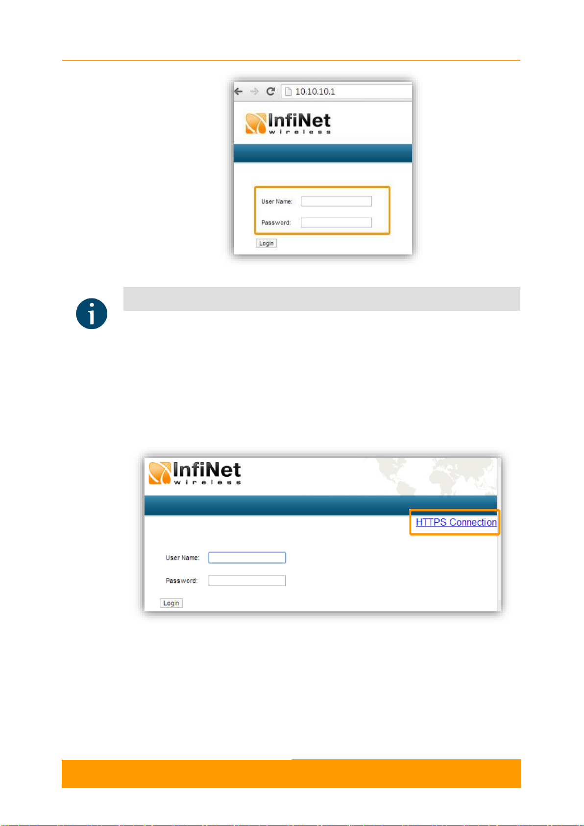
On the login page, you can type any username and any password and click Login:
Chapter 2 - Features set
User Manual
R5000 series - Web GUI
6
Figure 1 - GUI login
NOTE
Please change the credentials you have just inserted with a permanent username and
password for it after the first log in.
The default language is English. After the authentication step, the language can be
changed into Russian, French, Italian or Chinese.
You can access the unit via HTTPS (HTTP with SSL only) using InfiNet Wireless
self-signed certificate (from the Maintenance menu of Web interface). The «HTTPS
Connection» link is available in the right side of the login form:
Figure 2 - HTTPS connection
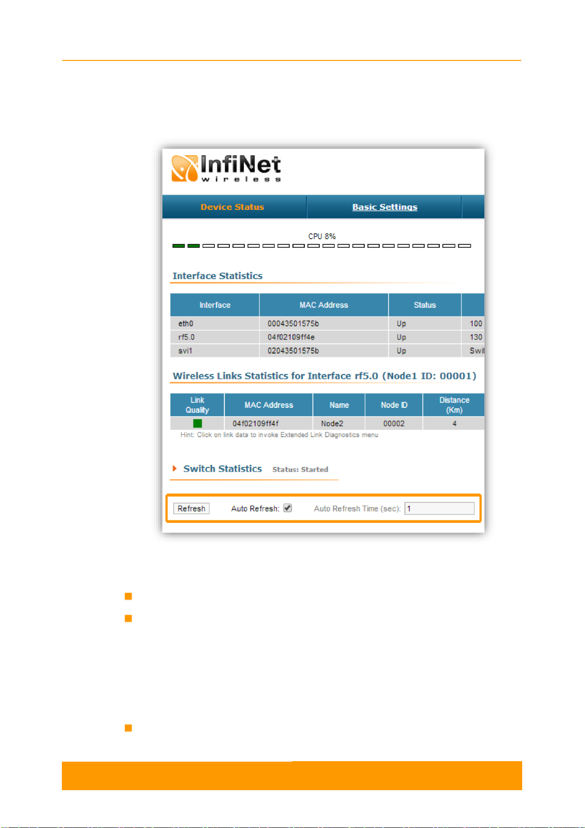
2.3. Device Status
The Device Status page is displayed by default after the authentication step. It
displays the main parameters of the unit in real-time. You can set the "Auto Refresh"
option to refresh the statistics automatically. Refresh frequency can be set by the
"Auto Refresh Time" parameter. The minimal possible value is “0” seconds and it
updates the information instantly.
Chapter 2 - Features set
User Manual
R5000 series - Web GUI
7
The device statistics can also be refreshed manually by pressing the «Refresh»
button.
These options are available in the bottom-left side of the Device Status screen:
Figure 3 - Refresh option
The Device Status page has the following sections:
CPU load - displays the load percentage of the CPU
Memory load:
- Memory (the data stored in volatile memoryare valid only during the current
session, until the system reset) displays in real-time the total memory
available and the used memory by the running processes
- Flash memory (non-volatile memory) displays in real-time the total memory
available and the used memory by the WANFleX and configuration files
Interface Statistics - displays the main parameters of all configured interfaces
(physical and logical)

Chapter 2 - Features set
User Manual
R5000 series - Web GUI
8
Wireless Links Statistics - displays the main parameters of all wireless
connections between the device and the neighbor devices
Switch Statistics - displays counters of the frames which have been switched
(e.g. the number of dropped packets and if they are dropped because of the
flood into their reachable destination, because of the STP, because of the
firewall, etc).
2.3.1. Interface Statistics
Parameter
Description
Interface
Displays all physical and logical set interfaces
MAC
Address
Displays the MAC address of each interface
Status
Displays for each interface whether it is “up and running” or
not
Mode
Displays the operation mode of each interface. E.g.:
- 10,100 or 1000 Mbps and half or full duplex for the
Ethernet interface
- Bitrate, frequency and bandwidth for the Radio interface
- Switch Group number for the SVI
Packets
Displays the number of received and transmitted packets for
each interface since the unit is operational. The local system
packets are counted, too (and not only the ones that are
passing through the switching groups - data traffic)
Errors
Displays the number of received and transmitted error
packets for each interface since the unit is operational
Load
Displays the packet flow through each interface in real-time
(for the system and the data traffic)
Table 1 - Interface Statistics
All these counters can be reset by pressing the «Reset All Counters» button:

Chapter 2 - Features set
User Manual
R5000 series - Web GUI
9
Figure 4 - Counters reset
CAUTION
Clearing these counters by pressing the «OK» button in the pop-up page means losing the
history data about the functionality of your unit. Avoid this operation unless you are
completely sure you don’t need these data in the future.
The MINT version is displayed in the right side of Interface Statistics section (e.g.:
MINTv1.90.5).
2.3.2. Wireless Links Statistics
This section displays the following information for the radio interface of the unit:
- Node name and ID
- Noise level
- Number of established links
- ATPC status (activated or deactivated)
- Autobitrate status (activated or deactivated)
- Polling mode
Parameter
Description
Link Quality
Gives a colorindication for the wireless connection quality
with the neighbor unit:
- Red: poor connection
- Yellow: good connection
- Green: excellent connection
MAC Address
Displays the neighbor’s MAC address

Chapter 2 - Features set
User Manual
R5000 series - Web GUI
10
Name
Displays the neighbor’s name
Node ID
Displays the sequential number of the neighboring node
Distance
Displays the calculated (theoretical) distance to the
neighbor unit (in Km)
Power
Displays the power level of the Tx and Rx signals of the
neighbor unit (in dBm)
Ref. Level
Displays the Tx and Rx signals levels for the minimal
available bitrate of the neighbor unit (in dB)
Current Level
Displays the Tx and Rx signals levels for current bitrate
of the neighbor unit (in dB)
Bitrate
Displays the set bitrate value for the Tx and Rx signals of
the neighbor unit
Retries
Displays the percentage of Tx and Rx retries of the
neighbor unit
Errors
Displays the percentage of Tx and Rx errors of the
neighbor unit
Load
Displays the number of kbps and packets that are going
inbound and outbound the radio interface of the neighbor
unit (main data)
Table 2 - Wireless Links Statistics
2.3.3. Switch Statistics
This section displays the number of unicast, broadcast and flood packets switched
within each Switch group and also within kernel system (internal traffic), in real-time
(since the last reboot):
Figure 5 - Switch Statistics
It also displays the number of dropped packets for: STP, unreachable destination,
firewall, possible loop, discard, MAC limits and reverse, within each Switch group
and kernel, in real-time (since the last reboot):

Chapter 2 - Features set
User Manual
R5000 series - Web GUI
11
Figure 6 - Switch Statistics
Total forwarded, dropped and ignored packets are displayed in real-time, too.
All these counters can be reset by pressing the «Reset All Counters» button.
Switch Statistics parameters:
Parameter
Description
Unicast
Sending a packet to a single host (network destination)
identified by a unique address
Broadcast
Sending a packet to all hosts (network destinations)
simultaneously (broadcasting is done by specifying a
special broadcast address on packets)
Flood
Sending a packet along the same link multiple times
(without specifying a destination address for the packets)
Several copies of the same packet would ultimately reach
all nodes in the network in flooding
STP
Spanning Tree Protocol - standardized as IEEE 802.1D
Creates a spanning tree within a network of connected
layer-2 bridges (typically Ethernet switches) and disables
those links that are not part of the spanning tree, leaving
a single active path between any two network nodes
The value displayed in the Switch Statistics table
represents the number of the packets blocked by the
Spanning Tree Protocol
Unreachable
The sender could not reach the specified network
destination
The value displayed in the Switch Statistics table
represents the number of the packets dropped because
they flood to unreachable destination
Firewall
A software or hardware-based network security system
that controls the incoming and outgoing network traffic by
analyzing the data packets and determining whether they
should be allowed through or not, based on applied rules
set
Other manuals for R5000 series
5
Table of contents
Popular Network Accessories manuals by other brands

Nortel
Nortel NTRN10AN Planning guide

AMG Systems
AMG Systems AMG5424R instruction manual

Paradyne
Paradyne COMSPHERE 6800 Series Multiplexer Management and Configuration Guide

ZyXEL Communications
ZyXEL Communications NMA1115 user guide

National Instruments
National Instruments FieldPoint FP-3000 user manual

Esse
Esse HI-PRO 1 Series user manual

Net Optics
Net Optics Gig Zero Delay Tap installation guide

Spirent communications
Spirent communications SmartBits 600x installation guide

METRObility Optical Systems
METRObility Optical Systems R711-11 Installation & user guide

Avaya
Avaya 4850GTS Series installation guide

Black Box
Black Box TS250A Specifications

Inline
Inline COURT DIRECTOR CD100 Operation manual


