2.
Position the soundbarin the desired location against the vehicle mounting bar. Use
4
of
the supplied mounting bracket bolts
to
secure each bracket
top
to
a bracket
base. T
wo
sets
of
bolts are supp
li
ed, allowing the soundbar
to
be mounted
to
pipes from 1" (25mm)
to
3-1
/2"
(89mm)
in
diameter.
a.
When the soundbar
is
in
the correct position, tighten the mounting bracket
adjustment screws.
3a.
Ru
n one end of one safety harness wire through one
of
the soundbar's harness
attachment loops, and use the supplied clamp to secure the wire.
IMPORTANT:
Be
sure
to
tighten
the
bolts on
the
clamp as
far
as
they
will go and
test
the connection
to
be
sure
that
the
safety harness
wire
is
secure in
the
clamp.
3b. Run the other end ofthe safety harness wire around the vehicle mounting bar and
use the supplied clamp to secure the wire.
IMPORTANT: Be sure
to
tighten the bolts
on
the
clamp as
far
as
they
will go and
test
the
connection
to
be
sure
that
the safety harness
wire
is
secure in
the
clamp.
3c. Repeat Steps
3a
and
3b
with the other safety harness wire, using the other
soundbar harness a
tt
achment loop and the vehicle mounting bar.
IMPORTANT: Besure
to
tighten
the
boltson the clamp as farasthey will go and
test
the connection
to
be sure that the safetyharness wires are secure in
the
clamps.
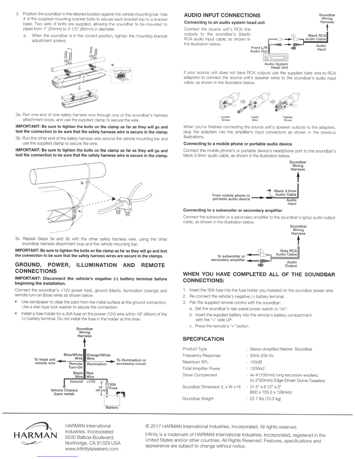
GROUND, POWER,
ILLUMINATION
AND REMOTE
CONNECTIONS
IMPORTANT:
Disconnect
the
vehicle's
negative
(-)
battery
terminal
before
beginning
the
installation.
Connect the soundbar's +12V power (red), ground
(b
lack), i
ll
umination (orange) and
remote turn-on (blue) wires as shown below.
Use sandpaper
to
clear the paint from the metal surface at the ground connection.
Use a star-type lockwasher to secure the connection.
Install a fuse holder for a
30A
fuse on the power(1
2V)
wire within 18" (46crn) ofthe
(+)
battery terminal. Do not install the fuse
in
the holder at this time.
Sound
bar
Wiring
Harfess
Blue/White
Orange/White
To
head
unit
......,
...,.....:.
W
.:.;
i
.:.;
r
e~.:.;
W
;.:;
ir
.:
e
__
___..
To
illuminati~n
C!r
remote
wir
e
Remote
Illumination
accessory
c1rcu1t
Turn-On
Black
Wire
!G
round
Vehicle
-C
has
sis
(bare metal)
Red
Wire
+12V
AUDIO INPUT CONNECTIONS
Connecting
to
an
audio
system
head
unit
Connect the source unit's RCA line
outputs
to
the soundbar's (black)
RCA audio input cable, as shown in
~
the illustration below.
--
Front
UR
Audio
Out
o~=ge::::J~i:;:
""
coooooooo
Audio
System
Head Unit
Sound
bar
Wiring
Harness
t
If your source unit does not have RCA outputs use
th
e supp
li
ed bare wire-to-RCA
adapters
to
connect the source unit
's
speaker wires to the soundbar's audio input
cable, as shown
in
the illustration below.
~
~
e
~
Loosen
Insert
Tig
hte
n
Screw W
ire
Sc
rew
When you're finished connecting the source uni
t's
speaker outputs to the adapters,
plug the adapters into the amplifier's input connectors as shown
in
the previous
illustrations.
Connecting
to
a
mobile
phone
or
portable
audio
device
Connect the mobile phone's
or
portable device's headphone port
to
the soundbar's
black 3.5mm audio cable, as shown
in
the illustration below.
Soundbar
Wiring
Harness
t
Connecting
to
a
subwoofer
or
secondary
amplifier
Connectthe subwoofer or a secondary ampli
fi
er to the soundbar's
(g
r
ay)
audio output
cabl
e,
as shown
in
the i
ll
ustration
be
low.
Sound
bar
Wirin
g
Hartess
WHEN YOU HAVE COMPLETED
ALL
OF THE SOUNDBAR
CONNECTIONS:
1. Insert the
30A
fuse into the fuse holder you installed
on
the soundbar power wire.
2. Re-connect the vehicl
e's
negative(-) battery terminal.
3. Pair the supplied remote control with the soundbar:
a.
Set the soundbar's rear-panel power switch
to
"on".
b. Insert the supp
li
ed battery into the remote's battery compartment
with
the"+"
side
UP.
c.
Press the remote's "+"button.
SPECIFICATION
ProductType
Frequency Response
Maximum SPL
Total Amplifier Power
Driver Complement
Soundbar Dimension
(L
x W x
H)
SoundbarWeight
Stereo Amplified Marine Soundbar
50Hz-20kHz
100dB
120Wx2
4x
4'(100mm) long excursion woofers;
2x 2'(50mm) Edge-Driven Dome
Tw
eeters
31.5"
X
6.
12"
X
5"
(800 x 155.5x 128mm)
22.7 lbs (10.3 kg)
~
HARMAN
HARMAN International
Industries,
In
corporated
8500
Balboa Boulevard,
Nort
hr
idge,
CA
91329 USA
vvww.infinityspeakers.corn
© 2017 HARMAN International Industries, Incorporated. All rights reserved.
~
Infinity is a
tr
ademark
of
HARMAN
In
ternation
al
Industries,
In
co
rporated, registered
in
the
United States an
d/or
other countries. A
ll
Rights Reserved. Features, specifications a
nd
appearance are subject
to
change without notice.