Infinitybox inMOTION INFMRSCZ User manual

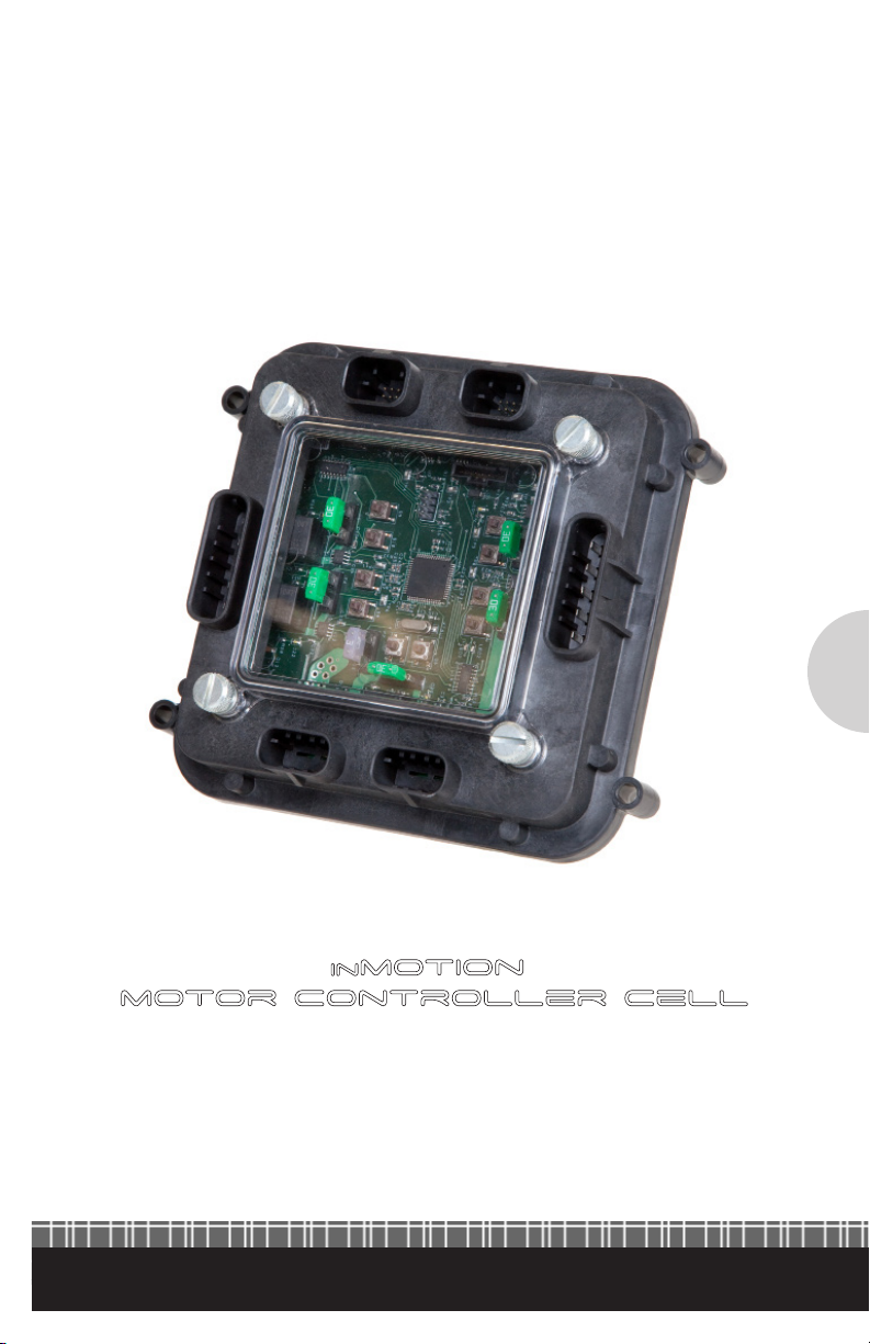
inmotion™
motor controller cell
www.innitybox.com
Innitybox, LLC
2
inmotion™
motor controller cell

www.innitybox.com
www.isispower.com
3
inMOTION™ MOTOR CONTROLLER CELL INSTRUCTIONS
Overview
The inMOTION™ Motor Controller Cell is a powerful addition to the Innitybox
System. You get full polarity control of 5 motors, solenoids or linear actuators to
control a broad range of accessories in your vehicle. Applications include windows,
power locks, convertible tops and sunroofs.
General Specications
Input Voltage Range: 8 to 19 VDC
Maximum Number of Outputs: 5 polarity reversed pairs
Output Node Technology: H‐Bridge Relay with current monitoring
Current Capability: 25‐amps per pair
Maximum Cell Temperature: 185°F (85°C)
Materials: All UL 94V0
Warnings
inMOTION controls things that move including motors, solenoids and linear actuators.
Use caution and be prepared for any movement when setting up, training and using
the system.
inMOTION’s current limiting capabilities are not intended to protect users from potential
injury caused by objects interfering with the travel of a mechanism in or on the vehicle.
Never operate the inMOTION Cell without both Power Connection Harnesses connected
to the Power Input Connectors.
Black wires on the Power Input Harnesses must be properly connected to vehicle ground.
Use included fuses and fuse holder to protect power feeds from the battery.
Polarity on Power Connection Harness must never be reversed. Reversing the voltage going
into the inMOTION Cell will damage the cell and void any warranty.
Do not use fuses higher than 25‐amps in the inMOTION Cell.
Kit Includes
1- inMOTION Cell with Cover
1- 2-Position JCASE Fuse
Protection Module
2- 50-Amp JCASE Fuses
1- Output Harness (A)
1- Output Harness (B)
2- Power Connection Harness
1- 2-Way CAN Cable
1- Bag of Assorted Mini fuses
4- 10 AWG Ring Terminals
1- 4 AWG Ring Terminal
1- Instruction Guide

www.innitybox.com
Innitybox, LLC
4
A- Output Connector for A Harness
B- Output Connector for B Harness
C- Power Connectors for Input Harnesses
D- Data Connectors for CAN Harnesses
E- Train Button
F1-F5- Output Fuses
F6- Fuse to protect relay coils
G- Programming Header
H- Address Header
J- Blue Heartbeat Indicator
Details of the inMOTION Cell
U U
F1 F2
F3
F4
F5
H
D
G
J
A
C
BE
F6
U
U
U
DD
D
D
D

www.innitybox.com
54
Connector Motor/Output Direction Color
A 1 Up/Forward Green
A 1 Down/Reverse Light‐Green
A 2 Up/Forward Blue
A 2 Down/Reverse Light‐Blue
A 3 Up/Forward Brown
B 3 Down/Reverse Tan
B 4 Up/Forward Orange
B 4 Down/Reverse Yellow
B 5 Up/Forward Grey
B 5 Down/Reverse White
Power Connection Harness
Output Harnesses
F1-F5- Output Fuses
F6- Fuse to protect relay coils
G- Programming Header
H- Address Header
J- Blue Heartbeat Indicator
Wire Color Connector Label Connection
Red A Battery Positive
Black B Chassis Ground
inMOTION Conguration
See the conguration sheet that was included with your inMOTION kit for the input
and output details. This information can also be found in the Resource section at
www.innitybox.com.

www.innitybox.com
Innitybox, LLC
ISIS™ Intelligent Multiplex System™
6
Installation Steps
1) Mount inMOTION Cell in vehicle using 4 mounting points in corners of cell.
2) Connect Primary Power to inMOTION Cell
a. Connect primary power wire from battery to single terminal on included fuse
protection module.
b. Connect red wires of Power Connection harnesses to two 6mm terminals on fuse
protection module.
c. Connect black wires of Power Connection harness to chassis ground.
d. Plug Power Connection harness into inMOTION Cell.
3) Connect Output Harnesses to Loads
a. Connect wires in outputs harnesses to wires going to motor or solenoid. Use
Output Harness table as a guide for specic wire colors..
b. Plug Output Connectors into inMOTION Cell. Use diagram on page 4 to identify
locations for A & B connectors.
c. Insert appropriate fuses into fuse holders F1 through F5. Fuse should be sized to
current draw for motor or solenoid.
d. Insert 3‐amp Mini® fuse into F6.
4) Connect switches to the MASTERCELL inputs.
a. Use the conguration sheet included in your kit for details on the wire colors for
each output and its direction.
b. MASTERCELL inputs are ground switched. Do not allow voltage to be applied to
any of the MASTERCELL input wires. This will damage the input and void your
MASTERCELL warranty.
5) Plug 2‐Way CAN Cable into one of the open connectors on inMOTION Cell. Plug other end
into available CAN connector on existing POWERCELL. Move terminator resistor from
existing POWERCELL to open CAN connector on inMOTION Cell.

www.innitybox.com
7
6) Insert jumpers into header (H) to set correct address for inMOTION Cell. Check your
conguration sheet. inMOTION cells are typically set to address 3. Check the Reference
Library section of www.innitybox.com for more details on setting the address header.
7) Insert included 50-amp JCASE cartridge fuses into primary fuse protection module and
connect the Innitybox system to the battery.
8) Check direction of motors and solenoids using switches under cover. Press the U & D
switches as shown in the picture to manually cycle the motor or the solenoid. Make sure
that the output moves in the up or forward direction when you press the U button closest
to the fuse for that output. Repeat with the D button to make sure that the output moves
in the down or reverse direction. WARNING!!! Pressing the manual buttons will provide
power to the outputs. Be prepared for the motor or solenoid attached to the output
to move.
9) Train the output to the inMOTION Cell after all motors or solenoids are attached.
a. Use the manual U & D (Up and Down) buttons to move all motor controlled
functions to a middle position. For example, use the U button to move a window
half-way up from the down position.
b. Press the Train button labeled S11 under the cover of the inMOTION Cell.
This will start the train sequence. Each output will cycle for 1 second in each
direction so that the inMOTION cell can learn the current draw for the motor
or solenoid attached to the output. WARNING!!! Pressing the train button will
provide power to the outputs. Be prepared for the motor or solenoid attached
to the output to move.
c. Outputs will not operate correctly from MASTERCELL inputs until the cell
is trained. You must repeat the training process if new outputs are attached
to inMOTION.

Infinitybox, LLC
1-847-232-1991
www.infinitybox.com
Warranty Policy
Warranty: Innitybox, LLC (“Innitybox”) warrants against any defects in materials and workmanship to
the Product’s INFINITYWIRE™ modules, wiring harnesses and accessory modules for a period of ve (5)
years from the rst date of purchase. Subject to the terms of this warranty described below, Innitybox will
replace any such defective Product that is returned to Innitybox within the ve (5) year period from initial
purchase. Replacement of any defective part or Product will not extend the applicable warranty period. The
warranty does not apply to: (i) any Product that is not installed in compliance with the applicable Product
documentation; (ii) any defect in, or failure of, the Product resulting from an accident, shock, negligence, water
immersion or misuse; (iii) any Product that has been modied, adjusted, repaired, or disassembled by any party
other than Innitybox; or (iv) any defect other than in materials and workmanship.
This warranty covers only the original purchaser of Product purchased from an Innitybox authorized dealer
in the United States. In order to receive warranty service, purchaser must provide Innitybox with a copy of
the receipt stating the dealer name, product purchased and date of purchase. Products found to be defective
during the warranty period will be replaced (with a product deemed to be equivalent or better) at the discretion
of Innitybox. Innitybox’s sole liability for any defective Product is limited solely to the replacement of
Product pursuant to this warranty. Innitybox reserves the right to replace any repairable parts with new or
refurbished parts.
INFINITYBOX DISCLAIMS ALL OTHER WARRANTIES, WHETHER EXPRESS, IMPLIED OR STATUTORY, SUCH
AS WARRANTIES OF MERCHANTABILITY AND FITNE SS FOR PURPOSE. IN NO EVENT SHALL INFINITYBOX
BE LIABLE FOR ANY PUNITIVE, INDIRECT, INCIDENTAL OR CONSEQUENTIAL DAMAGES, INCLUDING
WITHOUT LIMITATION, LIABILITY FOR LOSS OF USE, LOSS OF PROFITS, LOSS OF PRODUCT OR BUSINESS
INTERRUPTION HOWEVER THE SAME MAY BE CAUSED, INCLUDING NEGLIGENCE.
AA-INF-0622011_02 REV D
Popular Automobile Accessories manuals by other brands


ULTIMATE SPEED
ULTIMATE SPEED 279746 Assembly and Safety Advice

SSV Works
SSV Works DF-F65 manual

ULTIMATE SPEED
ULTIMATE SPEED CARBON Assembly and Safety Advice

Witter
Witter F174 Fitting instructions

WeatherTech
WeatherTech No-Drill installation instructions

TAUBENREUTHER
TAUBENREUTHER 1-336050 Installation instruction