infobit WP200-Kit User manual

File No.
RD-I-20-012
Version
1.1
WP200-Kit User Manual
Effective Date
2020-01-06
Page
1/ 26
1
Record page
No.
Revised summary description
Version
Revise
person
Revised
Date
1
Initial version
1.0
Alex
2020-01-02
2
Connected the “Auto System” function description
V1.1
Alex
2020-01-06
Approval:
Date:
Approve by:
Date:
Issue:Alex
Date:2020/01/06
File No.
RD-I-20-012
Version
1.1
WP200-Kit User Manual
Effective Date
2020-01-06
Page
2/ 26
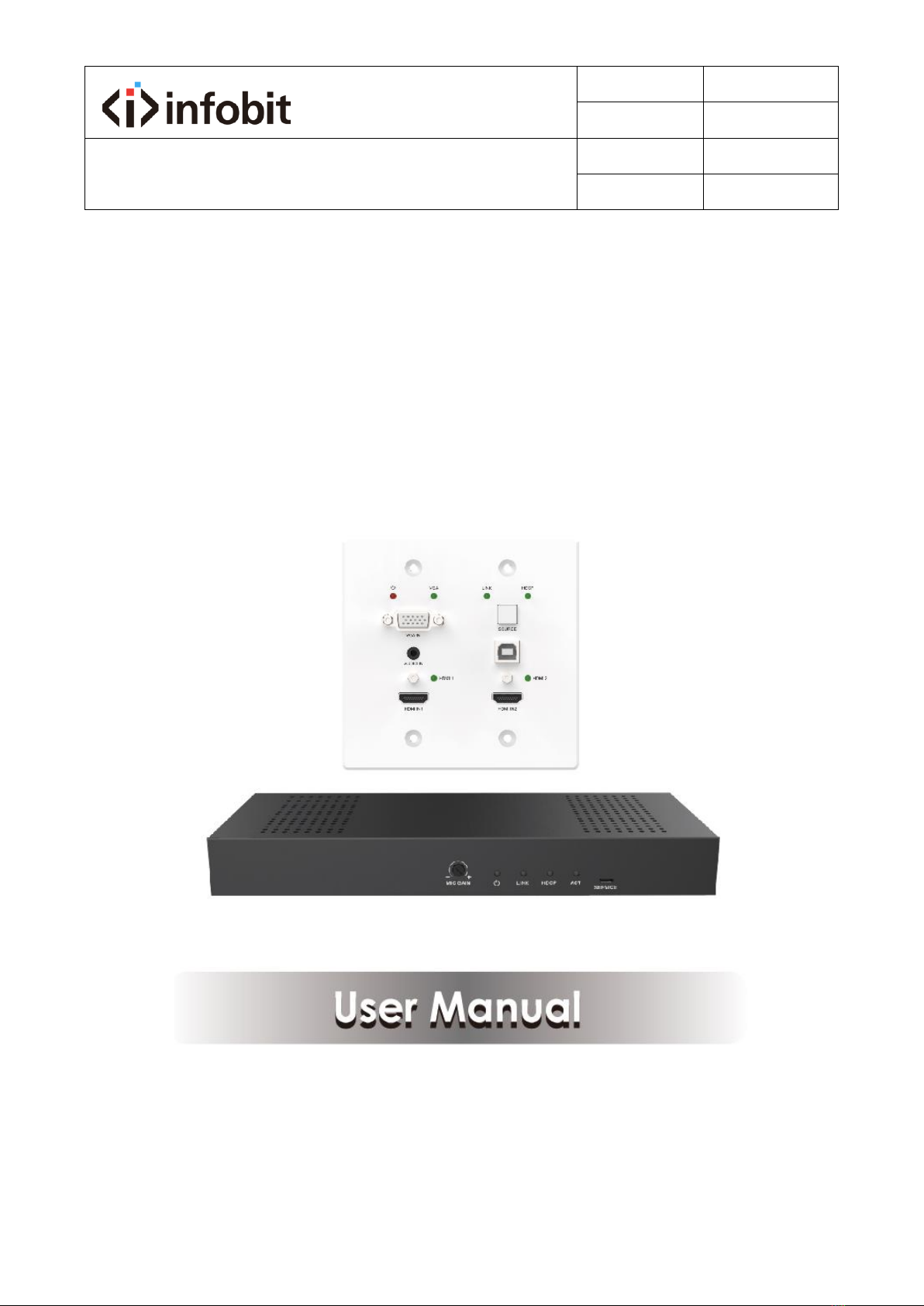
2
Multi-function AV intelligent
education system
Model: WP200-Kit
VER 1.1

File No.
RD-I-20-012
Version
1.1
WP200-Kit User Manual
Effective Date
2020-01-06
Page
3/ 26
3
Thank you for purchasing this product
For optimum performance and safety, please read these instructions carefully
before connecting, operating or adjusting this product. Please keep this manual
for future reference.
Surge protection device recommended
This product contains sensitive electrical components that may be damaged
by electrical spikes, surges, electric shock, lighting strikes, etc. Use of surge
protection systems is highly recommended in order to protect and extend the
life of your equipment.
Table of Contents
1. Introduction ...................................................................................................... 4
2. Features ............................................................................................................ 5
3. Package Contents .............................................................................................. 5
4. Specifications .................................................................................................... 6
5. Operation Controls and Functions...................................................................... 7
5.1 Transmitter Panel ...................................................................................... 7
5.2 Receiver Panel........................................................................................... 9
6. Web GUI User Guide........................................................................................ 10
7. System ON/OFF Subroutine ............................................................................. 23
8. Display ON/OFF Subroutine ............................................................................. 24
9. System Reset ................................................................................................... 25
10. Application Example ...................................................................................... 26

File No.
RD-I-20-012
Version
1.1
WP200-Kit User Manual
Effective Date
2020-01-06
Page
4/ 26
4
1. Introduction
The product is a multi-function AV intelligent education system. It offers 2HDMI and
VGA video extension, video switching, system control and analog audio amplification.
Uncompressed video and audio can be transmitted up to 230ft/70m. This design of
HDBaseT™ technology allows for full usage of HDMI and controls over CAT5e/6/6A
cable. The product supports Web GUI and panel button control.
Transmitter support HDCP 1.4, HDCP2.2 and can be switched manually, auto, hybrid
or priority. And the maximum distance can be up to 70m at 1920x1200@60Hz or up
to 40m at 4K @ 30 Hz.
Receiver support a microphone input, analog audio output, 2x30 at 4 ohms speaker
output, and Relay control to the projector screen rise and fall or RS-232 control to the
display power on and off. A USB port on the receiver will transmit interactive display
connections to the transmitter.
Control Panel supports volume control and system control. At the same time, it can
support 2 HDMI and one VGA input selection.

File No.
RD-I-20-012
Version
1.1
WP200-Kit User Manual
Effective Date
2020-01-06
Page
5/ 26
5
2. Features
☆ HDMI 1.4b, HDCP 2.2 and HDCP 1.4 compliant.
☆ Video resolutions up to 4K2K@30Hz, 1080p@120Hz and 1080P 3D@60Hz.
☆ Audio up to 7.1 channels of High Definition audio pass through (LPCM, Dolby
TrueHD, and DTS-HD Master Audio).
☆ HDBaseT™ over a single CAT5e/6/7 cable up to 230ft/70m distance.
☆ Support multi-VESA Standard VGA formats input.
☆ Supports MIC input.
☆ 2x30watts@4 ohms amplifier output.
☆ Supports interactive display USB pass-through.
☆ Supports Web GUI control.
☆ Supports control panel volume control and system control.
☆ Supports relay control.
☆ Supports RS-232 control.
3. Package Contents
① 1× HDMI Extender Transmitter
② 1× HDMI Extender Receiver
③ 1× 24V/3.75A DC Power Supply
④ 2× Mounting ears
⑤ 1× User Manual
Table of contents
Other infobit Projector Accessories manuals


