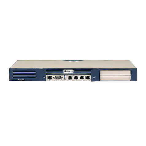
Infoblox Infoblox-250-A User manual

1
Contents
Introduction . . . . . . . . . . . . . . . . . . . . . . . . . . . . . . . . . . . . . . . . . . . . . . . . . . . . . . . . . . . . . . . . . . 3
Product Overview . . . . . . . . . . . . . . . . . . . . . . . . . . . . . . . . . . . . . . . . . . . . . . . . . . . . . . . . . . . . . . . . . . . . . . . . . . . . . . .3
Hardware Components. . . . . . . . . . . . . . . . . . . . . . . . . . . . . . . . . . . . . . . . . . . . . . . . . . . . . . . . . . . . . . . . . . . . . . . . . . .4
System, Environmental, and Power Specifications . . . . . . . . . . . . . . . . . . . . . . . . . . . . . . . . . . . . . . . . . . . . . . . . . . . .7
Installing an Appliance . . . . . . . . . . . . . . . . . . . . . . . . . . . . . . . . . . . . . . . . . . . . . . . . . . . . . . . . . 9
Rack Mounting . . . . . . . . . . . . . . . . . . . . . . . . . . . . . . . . . . . . . . . . . . . . . . . . . . . . . . . . . . . . . . . . . . . . . . . . . . . . . . . . .9
Powering the Appliance . . . . . . . . . . . . . . . . . . . . . . . . . . . . . . . . . . . . . . . . . . . . . . . . . . . . . . . . . . . . . . . . . . . . . . . . . .9
Cabling the Appliance to a Network . . . . . . . . . . . . . . . . . . . . . . . . . . . . . . . . . . . . . . . . . . . . . . . . . . . . . . . . . . . . . . 10
Accessing the Appliance . . . . . . . . . . . . . . . . . . . . . . . . . . . . . . . . . . . . . . . . . . . . . . . . . . . . . . . 11
Connecting to the Appliance . . . . . . . . . . . . . . . . . . . . . . . . . . . . . . . . . . . . . . . . . . . . . . . . . . . . . . . . . . . . . . . . . . . . 12
Specifying Appliance Settings. . . . . . . . . . . . . . . . . . . . . . . . . . . . . . . . . . . . . . . . . . . . . . . . . . . . . . . . . . . . . . . . . . . 13
Infoblox GUI . . . . . . . . . . . . . . . . . . . . . . . . . . . . . . . . . . . . . . . . . . . . . . . . . . . . . . . . . . . . . . . . . . . . . . . . . . . . . . . . . 15
Infoblox CLI . . . . . . . . . . . . . . . . . . . . . . . . . . . . . . . . . . . . . . . . . . . . . . . . . . . . . . . . . . . . . . . . . . . . . . . . . . . . . . . . . . 16
Copyright Statements
© 2010, Infoblox Inc.— All rights reserved.
The contents of this document may not be copied or duplicated in any form, in whole or in part, without the prior
written permission of Infoblox, Inc.
The information in this document is subject to change without notice. Infoblox, Inc. shall not be liable for any
damages resulting from technical errors or omissions which may be present in this document, or from use of this
document.
This document is an unpublished work protected by the United States copyright laws and is proprietary to Infoblox,
Inc. Disclosure, copying, reproduction, merger, translation, modification, enhancement, or use of this document by
anyone other than authorized employees, authorized users, or licensees of Infoblox, Inc. without the prior written
consent of Infoblox, Inc. is prohibited.
For Open Source Copyright information, see Open Source Copyright and License Statements in the Infoblox
Administrator Guide.
Trademark Statements
Infoblox, the Infoblox logo, Grid, NIOS, bloxTools, NetMRI and PortIQ are trademarks or registered trademarks of
Infoblox Inc.
All other trademarked names used herein are the properties of their respective owners and are used for
identification purposes only.
Infoblox Installation Guide
For the Infoblox-250-A Appliance

Contents
2 Infoblox Installation Guide
Warranty Information
Your purchase includes a 90-day software warranty and a one year limited warranty on the Infoblox appliance, plus
an Infoblox Warranty Support Plan and Technical Support. For more information about Infoblox Warranty
information, refer to the Infoblox website, or contact Infoblox Technical Support.
Company Information
Infoblox is located at:
4750 Patrick Henry Drive
Santa Clara, CA 95054-1851, USA
Web: www.infoblox.com
www.infoblox.com/support
Phone: 408.625.4200
Toll Free: 888.463.6259
Outside North America: +1.408.716.4300
Fax: 408.625.4201
Product Information
Hardware Models: Infoblox-550-A, -1050-A, -1550-A, 1552-A, -1852-A, and -2000-A
Document Number: 400-0293-000 Rev. A
Document Updated: August 23, 2010

For the Infoblox-250-A Appliance 3
Introduction
This guide provides an overview of the Infoblox-250-A network services appliance running NIOS version 5.1r1-4 and
later, and explains how to install and configure it. For information about the compatible software releases, refer to
the Knowledge Base (KB) article 13272 for details. For the most current version of the KB article, visit
http://www.infoblox.com/en/support/support-center-login.html.
Figure 1 Tasks in This Guide
Product Overview
The Infoblox-250-A network services appliance provides reliable, scalable, and secure core network services
including DNS (Domain Name System), DHCP (Dynamic Host Configuration Protocol), IPAM (IP Address
Management), IF-MAP and more. The integrated Infoblox approach combines the simplicity of appliances with the
power of advanced distributed database technology to control and automate services while achieving availability,
manageability, visibility, and control unparalleled by conventional solutions based on legacy technologies. You can
configure and manage the Infoblox-250-A through an easy- to-use Infoblox GUI that works seamlessly in Windows,
Linux, and Mac environments using standard web browsers. The Infoblox-250-A supports all services of the larger
Infoblox appliances (Infoblox-550-A, -1050-A, -1550-A, -1552-A, -1852-A, and -2000-A) except configuration as a
grid master or grid master candidate.
The Infoblox-250-A appliance is WEEE and RoHS compliant.
12
3
Learn about the Infoblox appliances.
"Introduction" on page 3 Install appliances.
"Installing an Appliance" on page 9
Equipment
Rack
Power
Source
Management
System
To
Network
Access appliances.
"Accessing the
Appliance" on page 11

Introduction
4 Infoblox Installation Guide
Hardware Components
The Infoblox-250-A appliance is a 1-U platform that you can easily mount in a standard equipment rack using the
mounting brackets and bolts that ship with each appliance. The front panel components include communication
ports and indicator lights. The rear panel components include the power connector and switch, fan, air vent, and
the model and serial number label.
Front Panel
The front panel components are shown in Figure 2 and described in Table 1. For explanations of the Ethernet port
LEDs, and console and Ethernet port connector pin assignments, see Ethernet Port LEDs on page 5 and Connector
Pin Assignments on page 6.
Figure 2 Infoblox-250-A, Front Panel
Table 1 Front Panel Components
Component Description
USB Port Reserved for future use.
Console Port A male DB-9 serial port for a console connection to change basic configuration settings
and view basic system functions through the CLI (command line interface). Use the
serial cable and connection adapters that ship with the appliance to make a console
connection to this port.
Only a properly grounded USB-to-Serial dongle is allowed to connect to the serial
console port. If the dongle is connected to a laptop, this laptop must be grounded
properly as well. Failure to do so may result in damage to the serial console port of the
Infoblox appliance. Infoblox is not responsible for such damage.
HA Port
Console Port
LAN2 Port
USB Port
MGMT Port
LAN1 Port
Drive Indicator
Power Indicator

Hardware Components
For the Infoblox-250-A Appliance 5
Ethernet Port LEDs
To see the link activity and connection speed of an Ethernet port, you can look at its Link/Act and Speed LEDs.
Figure 3 shows the status the LEDs convey through their color and illumination (steady glow or blinking).
Figure 3 LEDs
Drive Indicator An LED that flashes green to indicate when the hard drive processes data.
Power Indicator An LED that glows green when there is power to the appliance. When it is dark, the
appliance is not receiving power.
MGMT Port A 10/100/1000-Mbps gigabit Ethernet port that you can use for appliance management
or DNS service. You can enable the MGMT port and define its use through the GUI after
the initial setup.
HA Port A 10/100/1000-Mbps gigabit Ethernet port through which the active node in an HA
(high availability) pair connects to the network using a VIP (virtual IP) address. HA pair
nodes also use their HA ports for VRRP (Virtual Router Redundancy Protocol)
advertisements.
LAN1 Port A 10/100/1000-Mbps gigabit Ethernet port that connects a NIOS appliance to the
network. You must use the LAN1 port to set up the appliance initially. It handles all
traffic if you do not enable the MGMT and LAN2 ports. The passive node in an HA pair
uses this port to synchronize the database with the active node.
LAN2 Port A 10/100/1000-Mbps gigabit Ethernet port that connects a NIOS appliance to the
network. The LAN2 port is not enabled by default. You can enable the LAN2 port and
define its use through the GUI after the initial setup.
Component Description
Label Color Port Status
Link/
Act Steady Green Link is up but inactive
Blinking Green Link is up and active
Dark Link is down
Speed Steady Amber 1000 Mbps
Steady Green 100 Mbps
Dark 10 Mbps
SpeedLink/Act
SpeedLink/Act SpeedLink/Act
SpeedLink/Act
MGMT
LAN1
HA
LAN2

Introduction
6 Infoblox Installation Guide
Connector Pin Assignments
An Infoblox appliance has three types of ports on its front panel:
•USB port (reserved for future use)
•Male DB-9 console port
•RJ-45 10Base-T/100Base-T/1000Base-T auto-sensing gigabit Ethernet ports
The DB-9 and RJ-45 connector pin assignments are described in Figure 4. The DB-9 pin assignments follow the
EIA232 standard. To make a serial connection from your management system to the console port, use the RJ-45
rollover cable and two female RJ-45-to-female DB-9 adapters that ship with the appliance. The RJ-45 pin
assignments follow IEEE 802.3 specifications. All Infoblox Ethernet ports are auto-sensing and automatically adjust
to standard straight-through and cross-over ethernet cables. 10Base-T Ethernet and 100Base-T fast Ethernet use
the same two pairs of wires. The twisted pair of wires connecting to pins 1 and 2 transmit data, and the twisted pair
connecting to pins 3 and 6 receive data. For 1000Base-T connections, all four twisted-pair wires are used for
bidirectional traffic.
Figure 4 Connector Pin Assignments
21 345
6789
21346578
78653421
DB-9 Connector Pin Assignments
RJ-45 Connector Pin Assignments
Pin 10Base-T
100Base-T
Signal
1000Base-T
Signal
T568A
Straight-Through
Wire Color
T568B
Straight-Through
Wire Color
1Transmit+ BI_DA+ White/Green White/Orange
2Transmit- BI_DA- Green Orange
3Receive+ BI_DB+ White/Orange White/Green
4 (not used) BI_DC+ Blue Blue
5 (not used) BI_DC- White/Blue White/Blue
6Receive- BI_DB- Orange Green
7 (not used) BI_DD+ White/Brown White/Brown
8 (not used) BI_DD- Brown Brown
Male DB-9 Console Port
RJ-45 Ethernet Ports
Pin Signal Direction
1 (not used)
2 Receive Input
3 Transmit Output
4 DTE Ready Output
5 Ground —
6 DCE Ready Input
7 RTS (Request to Send) Output
8 CTS (Clear to Send) Input
9 (not used)
Legend: BI_D = bidirectional; A, B, C, D = wire pairings
(Looking into the console
port on an Infoblox
appliance)
(Looking into RJ-45
Ethernet ports on an
Infoblox appliance)

System, Environmental, and Power Specifications
For the Infoblox-250-A Appliance 7
Rear Panel
Figure 5 shows the rear panel components on the Infoblox-250-A appliance.
Figure 5 Infoblox-250-A, Rear Panel
Table 2 Rear Panel Components
System, Environmental, and Power Specifications
System specifications describe the physical characteristics of each appliance. Environmental specifications
describe the temperature and moisture limits it can withstand. Power specifications describe the electrical range
within which the appliance circuitry can operate.
Component Description
Model Number An identifier of the hardware model type and software type.
Serial Number The serial number of the appliance. Use it to register the appliance to obtain software
upgrades and technical support services.
Air Vent An air vent that allows warm air to flow out of the appliance. Do not obstruct.
Fan A fan to help maintain optimum operating temperature. Do not obstruct.
Power Outlet An IEC C-14 chassis plug for connecting the appliance to a standard AC power source.
On/Off Switch A power switch to turn the power supply of the appliance on and off.
Power Outlet
On/Off
Switch
Model Number
Serial Number Air
Vent Fan

Introduction
8 Infoblox Installation Guide
System Specifications
•Form Factor: 1-U rack-mountable appliance
•Dimensions: 1.75” H x 17.5” W x 15” D (4.45 cms H x 43.82 cms W x 38.1 cms)
•Weight: Approximately 13 pounds (5.9 kg)
•Ethernet Ports: MGMT, HA, LAN1, LAN2 – auto-sensing 10Base-T/100Base-T/1000Base-T
•Serial Port: DB-9 (9600/8n1, Xon/Xoff)
Environmental Specifications
•Operating Temperature: 35 to 95 degrees F (-0 to 35 degrees C)
•Storage Temperature: -40 to 112 degrees F (-40 to 50 degrees C)
•Relative Humidity: 5% to 95%, relative humidity (non-condensing)
Electrical Power Specifications
•Input Voltage
—U.S.: 100 – 240 VAC switchable, 47 – 63 HZ, 3 A
—Europe: 208 – 265 VAC switchable, 47 – 63 HZ, 2 A
•Output Power: 250 watts
•Power plug and cable specifications by region:
Region Plug Type Cable Type Max Power
Rating
Max Temperature
Rating
North
America
NEMA5-15P
3-prong male plug
VCTF 3C 18 AWG 7A, 125 V 75° C
Japan NEMA5-15P
3-prong male plug
VCFI 3G 12A, 125 V 60° C
Europe CEE7 standard VII
2-prong male plug
H05VV-F 6A, 250 V 70° C
United
Kingdom
LP-60L 3-prong male
plug with fuse
H05VV-F 10A, 250 V 70° C
China RVV 300/ 500 3C X
1.00mmSQ
IEC 320 C 13/
GB2099.1 G B1002
10A, 250V 70° C
Taiwan VCTF 3x1.25mm
70° C
IEC-60320-C13 (BME)/
BLACK-ICC
10A, 125V 70° C
Australia
New Zealand
RVV 300/500 3C X
1.00mmSQ
IEC 320 C13/
GB2099.1 GB1002
10A, 250V 70° C
India
South Africa
1.0/3 HO5VVF3
70° C
IEC-320 C-13/BS
546SABS
10A, 250V 70° C

For the Infoblox-250-A Appliance 9
Installing an Appliance
Follow these instructions to rack mount the appliance, connect it to a power source, and cable it to a network.
Review the Infoblox Safety Guide and follow the necessary precautions before you start.
Rack Mounting
The appliance mounts into a standard 19” (48 cms) equipment rack. In addition to the screws and brackets that ship
with the product, you also need a screwdriver with a cross-headed tip.
Attach the brackets to the appliance, and mount it to an equipment rack.
1. Remove the four screws that ship attached to the left and right sides of the appliance—two screws per side.
2. Remove the pair of brackets from the accessory kit that also ships with the appliance.
3. Position one bracket so that the two holes in the bracket align with two of the holes on one side of the
appliance.
Note: There are five evenly spaced holes on each side of the appliance. You can secure the brackets to any two
adjacent holes so that you can mount the appliance more or less deeply in the rack.
4. Secure the bracket to the appliance with two of the screws that you removed previously.
5. Secure the second bracket in the same position on the other side of the appliance.
6. Attach the brackets to the equipment rack using the screws from the accessory kit.
Powering the Appliance
Use the power cable that ships with the Infoblox appliance to connect it to a power source.
1. Make sure that the power switch on the appliance is turned off.
2. Connect a power cable between the power connector on the back of the appliance and a properly grounded and
rated power circuit that meets the provisions of the current edition of the National Electrical Code, or other
wiring rules that apply to your location. Make sure that the outlet is near the appliance and is easily accessible.
3. Turn on the power switch.

Installing an Appliance
10 Infoblox Installation Guide
Cabling the Appliance to a Network
Use the Ethernet cables that shipped with the product to connect the appliance to the network.
1. Connect an Ethernet cable from the LAN1 port on the appliance to your network switch or router.
2. If you want to connect your appliance for HA (high availability), connect the HA ports on both appliances to a
switch on your network. The VIP (Virtual IP), LAN1, and HA port addresses must be on the same subnet and
must be unique for that subnet.
Figure 1 Cabling a Single Appliance and an HA Pair to a Network
Note: By default, an Infoblox appliance automatically negotiates the optimal connection speed and
transmission type (full or half duplex) on the physical links between its LAN1, LAN2, HA, and MGMT ports and
the Ethernet ports on a connecting switch. If the two appliances fail to auto-negotiate the optimal settings, see
the
Infoblox Administrator Guide
for steps you can take to resolve the problem.
3. To ensure that VRRP (Virtual Router Redundancy Protocol) works properly, configure the following settings at
the port level for all the connecting switch ports (HA, LAN1, and LAN2):
—Spanning Tree Protocol: Disable. For vendor specific information, search for “HA” in the Infoblox
Knowledge Base system at http://www.infoblox.com/en/support/support-center-login.html
—Trunking: Disable
—EtherChannel: Disable
—IGMP Snooping: Disable
—Port Channeling: Disable
—Speed and Duplex settings: Match these settings on both the Infoblox appliance and switch
—Disable other dynamic and proprietary protocols that might interrupt the forwarding of packets
4. Use the Infoblox GUI to access the Infoblox appliance from a management system. Through the GUI, you can
set up and administer the appliance. For management system requirements and access instructions, see
Accessing the Appliance on page 11.
Infoblox
Appliance
Switch or
Router Management
System
When cabling a single Infoblox appliance to the
network, connect an Ethernet cable from the LAN1 port
on the appliance to a switch or router.
When cabling a pair of Infoblox-250-A appliances to
the network for high availability, connect Ethernet
cables from the LAN1 and HA ports on each appliance
to a switch or router.
Infoblox
Appliance
Management
System Switch or
Router

For the Infoblox-250-A Appliance 11
Accessing the Appliance
The management system is the computer from which you configure and monitor the Infoblox appliance. You can
access the appliance from the management system remotely across an Ethernet network or directly through a serial
cable.
After completing the steps in Cabling the Appliance to a Network on page 10, you can make an HTTPS connection to
the appliance and access the Infoblox GUI using one of the supported browsers.
Alternatively, you can make an SSHv2 connection and access the CLI through an SSHv2 client. You can also access
the CLI by connecting a serial cable directly from the console port of a management system to the console port on
the appliance, and then using a terminal emulation program.
The management system must meet the following requirements to operate an Infoblox appliance.
Table 1 Software and Hardware Requirements for the Management System
Management System Software Requirements Management System Hardware Requirements
Infoblox GUI ACCESS
•Microsoft®Internet Explorer®8.0+ or Mozilla
Firefox 3.5 + on Microsoft Windows 7®
•Microsoft Internet Explorer®7.0+ and 8.0+ or
Mozilla Firefox 3.5 + on Microsoft Windows Vista®
•Microsoft Internet Explorer®7.0+ and 8.0+ or
Mozilla Firefox 3.5 + on Microsoft Windows XP®
(SP2+)
•Mozilla Firefox 3.5 + on Red Hat®Enterprise Linux®
or Fedora Core 8 and higher
•Safari 3.2+ and 4.x+ on Apple Mac OS® Xv10.5 and
higher
CLI ACCESS
•Secure Socket Shell (SSH) client that supports
SSHv2
•Terminal emulation program, such as minicom or
Hilgraeve Hyperterminal®.
•Minimum System:
500 MHz CPU with 256 MB RAM available to the
Infoblox GUI, and 256 Kbps connectivity to an
Infoblox appliance
•Recommended System:
1 GHz (or higher) CPU with 512 MB RAM available
for the Infoblox GUI, and network connectivity to an
Infoblox appliance
•Monitor Resolution:
Minimum: 1024 x 768
Recommended: 1280 x 800 or better

Accessing the Appliance
12 Infoblox Installation Guide
Connecting to the Appliance
Before you can configure the Infoblox appliance through the Infoblox GUI, you must be able to make a network
connection to it. You must use the LAN1 port to connect to the appliance. The default network settings of the LAN1
port are 192.168.1.2/24 with a gateway at 192.168.1.1 (the HA, MGMT, and LAN2 ports do not have default
network settings). To change these settings to suit your network, use either the LCD or the console port.
LCD
The Infoblox appliance has an LCD and navigation buttons on its front panel. At startup, the Infoblox logo appears
in the LCD on the front panel of the appliance. Then the LCD scrolls repeatedly through a series of display screens.
1. To change the network settings from the default, press one of the navigation buttons.
The LCD immediately goes into input mode.
2. Use the navigation buttons to enter the IP address, netmask, and gateway for the LAN1 port.
You can disable LCD input functionality. To disable the LCD, refer to the NIOS Administrator Guide.
Console Port
The Infoblox appliance has a male DB-9 console port on the front panel. You can log in to the appliance through this
port and specify initial network settings using the Infoblox CLI.
Note: Only a properly grounded USB-to-Serial dongle is allowed to connect to the serial console port. If the dongle
is connected to a laptop, this laptop must be grounded properly as well. Failure to do so may result in damage to
the serial console port of the Infoblox appliance. Infoblox is not responsible for such damage.
1. Connect a console cable from the console port of the management system to the console port of the Infoblox
appliance.
2. Using a serial terminal emulation program such as Hilgraeve Hyperterminal®(provided with Windows®
operating systems), launch a session. The connection settings are:
—Bits per second: 9600 — Stop bits: 1
—Data bits: 8 — Flow control: Xon/Xoff
—Parity: None
3. Log in using the default user name and password admin and infoblox. User names and passwords are
case-sensitive.
4. To change the network settings from the default, enter the set network command. Then enter information
as prompted to change the IP address, netmask, and gateway for the LAN1 port.
Infoblox > set network
NOTICE: All HA configuration is performed from the GUI. This interface is used only to
configure a standalone node or to join a grid.
Enter IP address: LAN1 port IP address
Enter netmask: [Default: 255.255.255.0]: netmask
Enter gateway address [Default: n.n.n.1]: gateway IP address
Become grid member? (y or n): n
After you confirm your network settings, the appliance automatically restarts.

Specifying Appliance Settings
For the Infoblox-250-A Appliance 13
Specifying Appliance Settings
When you make the initial HTTPS connection to the Infoblox appliance, you see the Setup Wizard, which
guides you through the basic deployment of the appliance on your network.
You can deploy an appliance individually or in an HA (high availability) pair, for hardware redundancy. A single
appliance or an HA pair without a Grid license runs independently from a grid. A grid is a group of two or more
Infoblox appliances that share sections of a common, distributed, built-in database and which you configure
and monitor through a single, secure point of access—the grid master. To set up a grid, you must configure a
single or HA grid master and at least one grid member, which can also be a single appliance or an HA pair.
The following instructions guide you through the wizard and include worksheets where you can note your
appliance and network settings. After you complete the wizard, you can set additional operational parameters
and configure the appliance to provide services, such as DNS and DHCP. For detailed instructions on
configuring the appliance, refer to the NIOS Administrator Guide.
1. Open an Internet browser window and enter https://
<IP address or hostname of your NIOS appliance>
.
2. Accept the certificate when prompted.
A certificate warning appears during the login process. This is normal because the NIOS appliance generates
a self-signed certificate when it first starts, and your browser does not have a trusted CA certificate or a
cached NIOS appliance server certificate (saved from an earlier connection) to authenticate the NIOS
appliance certificate. Also, the hostname in the default certificate is www.infoblox.com, which is unlikely to
match the hostname of your NIOS appliance. Consequently, messages appear warning that the certificate is
not from a trusted certifying authority and that the hostname on the certificate is either invalid or does not
match the name of the site that sent the certificate. Either accept the certificate just for this session or save it
to the certificate store of your browser.
To eliminate the certificate warning, generate a new self-signed certificate or import a third-party certificate
with a common name that matches the FQDN (fully-qualified domain name) of the appliance. This is a very
simple process. For information about certificates, refer to the NIOS Administrator Guide.
3. Log in using the default user name and password admin and infoblox.
Note: User names and passwords are case-sensitive.
4. Read the Infoblox End-User License Agreement and click I Accept to proceed.
5. The Setup Wizard opens, and you can enter basic network and deployment settings.
Determine how you want to deploy the appliance, and then use the following worksheets to note the network
settings that you want to enter on the wizard screens. If you are configuring an HA pair, you must configure
each node individually.

Accessing the Appliance
14 Infoblox Installation Guide
Use the following worksheet when configuring a single independent appliance or grid member:
* For grid member
** For an independent appliance
Use the following worksheet when configuring an independent HA pair:
On the last screen of the wizard, click Finish. The Infoblox GUI application restarts. If you configured an HA pair, use
the VIP address when you make an HTTPS connection to the HA pair.
Settings Enter your information here
Grid Name
Shared Secret Host Name
Grid Master’s IP Address
LAN1 Port IP Address and Netmask
Gateway IP Address
*Port Settings
**Admin Password
**Local Date, Time, and Time Zone
or
NTP Server IP Address
Settings Enter your information here
System Name
Shared Secret
Host Name
Virtual Router ID
VIP (Virtual IP) Address and Netmask
Node 1: HA Port IP Address
Node 2: HA Port IP Address
Node 1: LAN1 IP Address
Node 2: LAN1 IP Address
Gateway IP Address
Admin Password
Local Date, Time and Time Zone
or
NTP Server IP Address

Infoblox GUI
For the Infoblox-250-A Appliance 15
Infoblox GUI
You can view data and configuration settings and make configuration changes through the Infoblox GUI. When an
Infoblox appliance functions as an independent appliance, you launch System Manager to access the Infoblox GUI.
When the appliance is in a grid, you log in to the grid master and launch Grid Manager.
Figure 1 Infoblox GUI Overview
Finder Panel Workspace Toolbar Help panel
System Messages Breadcrumbs Navigation Global Search

Accessing the Appliance
16 Infoblox Installation Guide
Infoblox CLI
The Infoblox CLI allows you to configure and monitor the appliance using a small set of Infoblox commands. There
are some tasks, such as resetting the appliance, that you can only do through the CLI. You can access the Infoblox
CLI through a direct console connection from your management system to the Infoblox appliance. (For more
information, see Console Port on page 12.) You can also enable remote console access—that is, SSHv2 (Secure Shell
version 2) access—through the Infoblox GUI or CLI, and then access the CLI from a remote location using an SSHv2
client. (For more information, refer to the
NIOS Administrator Guide
.)
Using CLI Help
You can display a list of available CLI commands by typing help at the command prompt. For example:
Infoblox > help
? Display help
delete Delete files
dig Perform a DNS lookup and print the results
exit Exit command interpreter
help Display help
ping Send ICMP ECHO
quit Exit command interpreter
reboot Reboot device
reset Reset system settings
set Set current system settings
show Show current system settings
shutdown Shutdown device
traceroute Route path diagnostic
ddns_add Send DDNS update to add a record
ddns_delete Send DDNS update to delete a record
rotate Rotate files
To view an in-depth explanation of a CLI command and its syntax, type help command after the command
prompt. For example:
Infoblox > help rotate
Synopsis:
rotate log [ syslog | debug | audit | ifmapserver ]
rotate file groupname filename [ filename2, filename3, ...]
Description:
Rotates the specified log file, up to 10 previous.
logfiles will be preserved
The two main groups of Infoblox CLI commands are set and show. To see the complete list of the set commands,
enter help set after the command prompt. Likewise, to see a complete list of the show commands, enter help
show. For information about the CLI commands, refer to the Infoblox CLI Guide
Table of contents
Other Infoblox Network Hardware manuals
Infoblox
Infoblox 4005 Series User manual
Infoblox
Infoblox TE-2210 User manual
Infoblox
Infoblox 2200 Series User manual
Infoblox
Infoblox Trinzic Reporting 1400 User manual
Infoblox
Infoblox Trinzic 100 User manual
Infoblox
Infoblox Trinzic TE-2205 User manual
Infoblox
Infoblox 1405 Series User manual
Infoblox
Infoblox 2205 Series User manual

Infoblox
Infoblox SoT-1405 Series User manual
Infoblox
Infoblox NT-1400 User manual
