inform InfoSTS User manual

CONTENTS
OVERVIEW ________________________________________________________________________1
InfoSTS………………………………………………………………………………………………………… 1
DESCRIPTION OF THE FUNCTIONS OF THE InfoSTS…………………………………………………1
BLOCK DIAGRAM OF THE STS…………………………………………………………………………… 4
MANUAL TRANSFER SWITCH……………………………………………………………………………..5
SAFETY WARNINGS………………………………………………………………………………………... 6
FRONT VIEWS OF THE STS……………………………………………………………………………….. 7
VIEW OF THE CONTROL PANEL…………………………………………………………………………. 8
INSTALLATION ____________________________________________________________________9
PREPARATION FOR INSTALLATION…………………………………………………………………………9
PRELIMINARY INFORMATION…………………………………………………………………………….. 9
ELECTROMAGNETIC COMPATIBILITY………………………………………………………………….. 9
INSTALLATION ENVIRONMENT………………………………………………………………………….. 9
REMOVING THE STS FROM PALLET……………………………………………………………………. 9
PRELIMINARY CHECK OF CONTENTS………………………………………………………………….. 10
INSTALLING THE STS………………………………………………………………………………………. 10
ELECTRICAL CONNECTIONS ________________________________________________________11
DIAGRAMS OF CONNECTION TO THE ELECTRICAL SYSTEM…………………………………….. 11
PROTECTIONS INSIDE THE STS…………………………………………………………………………. 11
CABLE SIZES………………………………………………………………………………………………….12
CONNECTIONS………………………………………………………………………………………………. 12
WIRING PROCEDURE………………………………………………………………………………………. 16
PROTECTIVE EARTH……………………………………………………………………………………….. 16
R.E.P.O (REMOTE EMERGENCY POWER OFF)……………………………………………………………. 16
USE ______________________________________________________________________________17
DESCRIPTION………………………………………………………………………………………………… 17
PRELIMINARY OPERATIONS……………………………………………………………………………… 17
POWERING ON FOR THE FIRST TIME…………………………………………………………………… 17
Switching On (Normal Operation) The STS From Off Position……………………………………… 18
Switching To Maintenance Bypass Position From Normal (automatic) Operation……………… 19
Switching From Maintenance Bypass To Normal Operation…………………………………………20
Switching Off The STS During Normal Operation……………………………………………………... 21
DISPLAY 22
ALPHANUMERIC LCD DISPLAY, MIMIC DIAGRAM, KEY SYMBOLS………………………………. 22
DISPLAY MENUS…………………………………………………………………………………………….. 23
MAIN MENU…………………………………………………………………………………………………… 23
MEASURES MENU ………………………………………………………………………………………….. 24
COMMAND MENU……………………………………………………………………………………………. 25
ALARMS MENU……………………………………………………………………………………………… 26
OPTIONS MENU……………………………………………………………………………………………… 27
TIME MENU…………………………………………………………………………………………………… 29
INFORMATION MENU………………………………………………………………………………………. 29
ADJUST MENU………………………………………………………………………………………………. 29
SERVICE PASSWORD……………………………………………………………………………………… 29
USER PASSWORD………………………………………………………………………………………….. 30
ALARM MESSAGES………………………………………………………………………………………… 30
INPUT SOURCE ALARM DESCRIPTIONS…………………………………………………………………… 31
TRANSFER FLOWCHART……………………………………………………………………………………… 31
OPTIONAL EXTERNAL POWER INPUT……………………………………………………………………… 32
COMMUNICATION INTERFACE AND REMOTE MANAGEMENT…………………………………………32
OPTIONAL TCP/IP ADAPTOR…………………………………………………………………………………. 34
TECHNICAL SPECIFICATIONS _______________________________________________________35
MECHANICAL CHARACTERISTICS___________________________________________________ 38
MAINTENANCE AND TROUBLESHOOTING _____________________________________________39
TCP/IP ADAPTOR SETUP____________________________________________________________40

- 1 -
OVERVIEW
InfoSTS
Thank you for choosing InfoSTS as your equipment protector.
It includes many features to protect your critical equipments.
Power ranges according to models
4 pole model 3 pole model Output current per phase
STS450 STS350 50 amperes
STS4100 STS3100 100 amperes
STS4150 STS3150 150 amperes
STS4200 STS3200 200 amperes
STS4300 STS3300 300 amperes
STS4400 STS3400 400 amperes
This unit supplies continuous power to critical loads from 2 separate AC supplies. It monitors 2 input sources, if
one of the input sources fails, it transfers the load to the other input source automatically. The user can also
perform transfer from one source to another using the manual transfer switch.
The main functions of the STS unit are as follows :
•Increased power quality
•Increased noise reduction
•Power blackout protection
•Power redundancy
•Automatic static switching
•Remote monitoring of input power sources
•Easy static and mechanical transfer between separate input sources
•Remote management of power events
•Power event logging
•Redundancy
Therefore inclusion of INFORM Static Transfer Switches (STS) in an energy distribution system provides secure
protection against any possible faults in the AC power system. STS permits switching between two independent
AC power supplies (SOURCE 1 and SOURCE 2) without shutting down the critical load connected to its output.
DESCRIPTION OF THE FUNCTIONS OF THE InfoSTS
InfoSTS is a microprocessor controlled transfer switch, designed for automatic and manual switching between
two AC power sources, with interruption to the load of less than 2 msecs with synchronized sources and of less
than 12 msecs for unsynchronized sources.
STS utilizes SCRs connected in opposite parallel pairs (six pairs for 6 pole models ,eight pairs for 4 pole
models) . Three or four pairs of SCRs are used to connect the AC load to the power supply input referred to as
“PREFERRED”, under normal conditions. The other three (of four) pairs of SCRs are on standby to transfer the
load to the other power supply input referred to as “ALTERNATE” in case of a failure of the “PREFERRED”
input supply.
Source 1 and Source 2 supply inputs should come from two different AC sources with nominally identical
voltages, phases and frequencies. The aim of the STS is uninterrupted transfer from one AC power supply to
the other, in case of a fault in the “PREFERRED” supply.
Before and during transfer from one source to the other, the operating conditions of the SCRs are carefully
monitored to prevent crosscurrents between two sources. The break-before-make technique makes healthy and
uninterrupted transfers possible.

- 2 -
During normal operation, “PREFERRED” network supplies the load when both inputs are available. Selection of
the “PREFERRED” network, automatic re-transfer, retransfer delay, overload behavior of STS, alarm hold time,
nonsynchronized transfer behavior, overload and transfer inhibit reset modes may be set by the user on the
control panel of the unit.
Permitted voltage, phase difference and frequency tolerance are also adjustable by the service personnel on the
control panel.
Basic Features:
•Easy monitoring all parameters on LCD display
•Fast microcontroller (32 mips)
•Advanced RS232 communication features ,optional TCP/IP connection
•DRY contact alarm interface
•Password protected login system from remote site (timed Access)
•2 redundant power supplies for electronic boards (hot swappable)
•Easy front access to all components inside of the STS
•Second protection cover on live circuits which prevents electrical shock
•Input sources protected by fuses
•3 positioned Maintenance bypass switch which prevents cross currents between input sources
•User adjustable parameters by entering a password.
•Built in real time clock.
•Alarm history (with their date and time)
•Automatic transfer test from a remote site or using front panel
•Front panel Lamp test
•External emergency shutdown (EPO) input
•All boards are supplied by two separate power supplies.
•Hot plug construction during maintenance bypass
•High current output tolerant up to 1000%
•Adjustable long dead time during non synchron transfer up to 3 seconds
•SCR fault sense circuit
•Cabinet inside temperature sensor
•Fast voltage black-out circuit
•Input phase balance and phase sequence fault detect circuit
•Output alternance balance sense circuit
•Adjustable Input source frequency lower/upper limits
•Additional analog synchronous sense circuit
Control Circuit locations
The control circuits are located in a closed cabinet which is not directly accessible by the user.
Redundant power supply circuit
2 power supplies are installed inside the STS. They are connected to all boards separately. So the construction
is hot swappable. During operation, service personnel can replace one of the power supplies without effecting
the operation of the STS.
Power connections and terminals
All input and output power connections are located at the bottom of STS. At the bottom of the STS separate
panels let to the cables for easy installation.
Easy front Access to all components
All components are installed onto the front side of STS. During servicing, there is no need to remove any side or
rear panel of the STS.
Quick Access to static bypass switch
User can perform static transfer from remote panel but this will take a long time to surf on menu functions. A
separate static bypass switch is installed inside the STS and the priority of this switch is higher than the front
panel controls. This means that, it the user uses the manual bypass switch, all panel bypass commands will be
disabled.
- 3 -
Protections
- Two input sources are connected to STS by MCCB’s (S1 and S2)
- Suitable rating varistors protect the control circuits from high voltage transients.
- All power supply inputs are fuse protected
On SCR’s heat-sink, there is a thermal contact to warn the user in case of excessive heat-sink temperature.
Protection shield prevents direct touch to live parts, inside the unit.
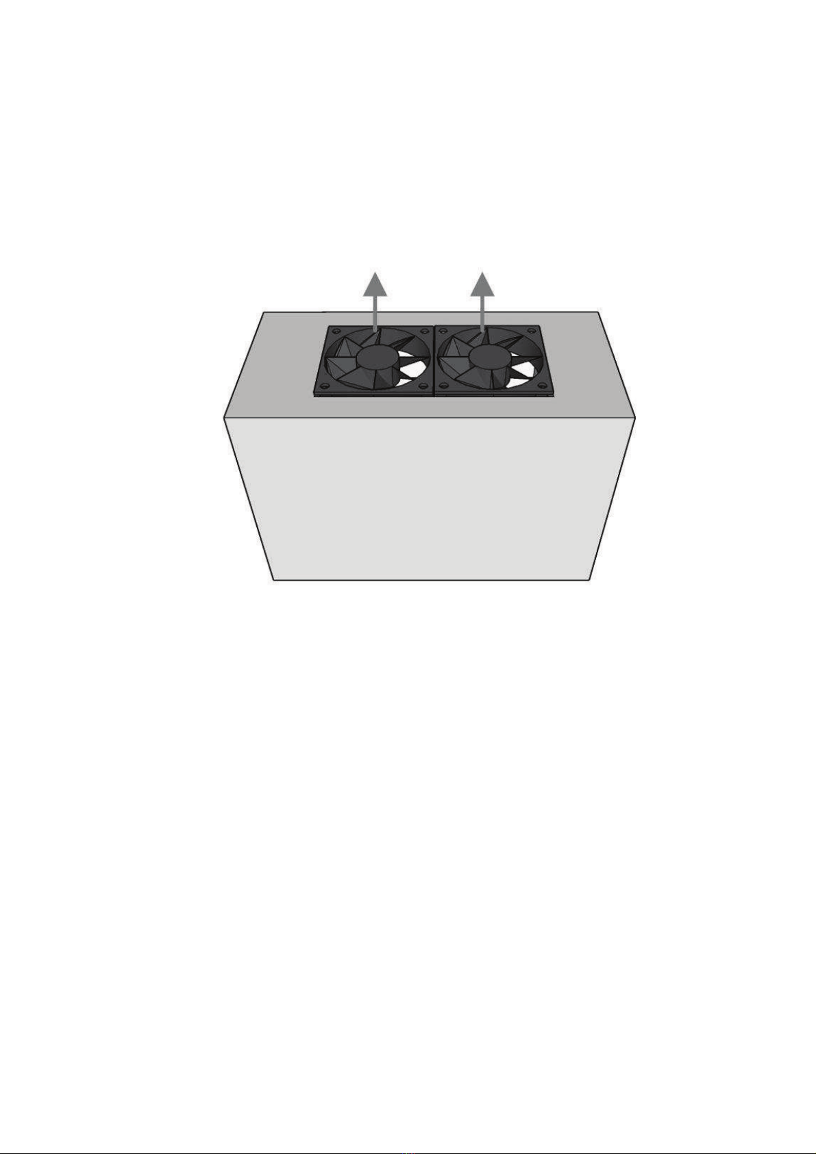
Cooling
The cooling fans ( 2 cooling fans) are installed on to the top side of STS .
Figure – 1 Cooling outlets of the STS
- 4 -
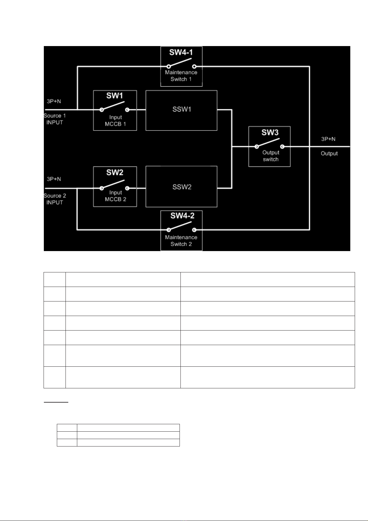
BLOCK DIAGRAM OF THE STS
Figure – 2 STS Block diagram
S1 Source 1 input circuit breaker (MCCB) This switch is thermal and magnetic protected type and
shutdowns source 1 input
S2 Source 2 input circuit breaker (MCCB) This switch is thermal and magnetic protected type and
shutdowns source 1 input
S4-1 Mechanical bypass switch to source 1 During maintenance these contacts connect Source 1 input
to STS output directly
S4-2 Mechanical bypass switch to source 2 During maintenance these contacts connect Source 2 input
to STS output directly
S3 Output switch This switch shutdowns the output voltage of STS . During
maintenance the position of this switch must be OFF.
SS1 Static transfer SCR circuit to source 1
This static switch contains SCRS and snubber components
and driven by a driver circuit which is controlled by the
microprocessor.
SS2 Static transfer SCR circuit to source 2
This static switch contains SCRS and snubber components
and driven by a driver circuit which is controlled by the
microprocessor.
NOTE : Figure 2 shows only 1 phase of 3 phase construction. The other phases are not shown.
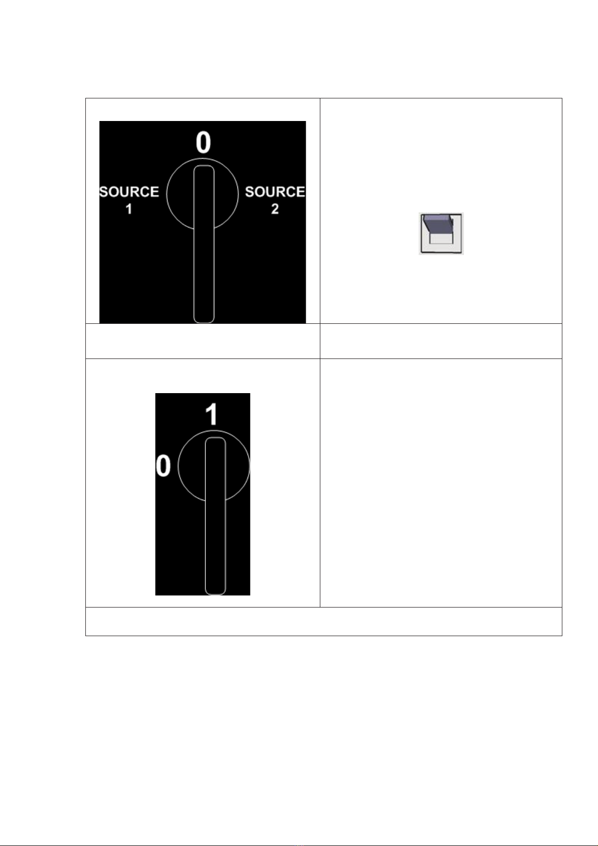
The maintenance bypass switch is a 3 pole change-over switch
1 Maintenance bypass to source1
0 Automatic operation
2 Maintenance bypass to source2
Source 1 and Source 2 input circuit breakers are MCCB’s with thermal overload and magnetic short circuit
releases.
A Manual Static Bypass Switch is also available for easy load transfer.

- 5 -
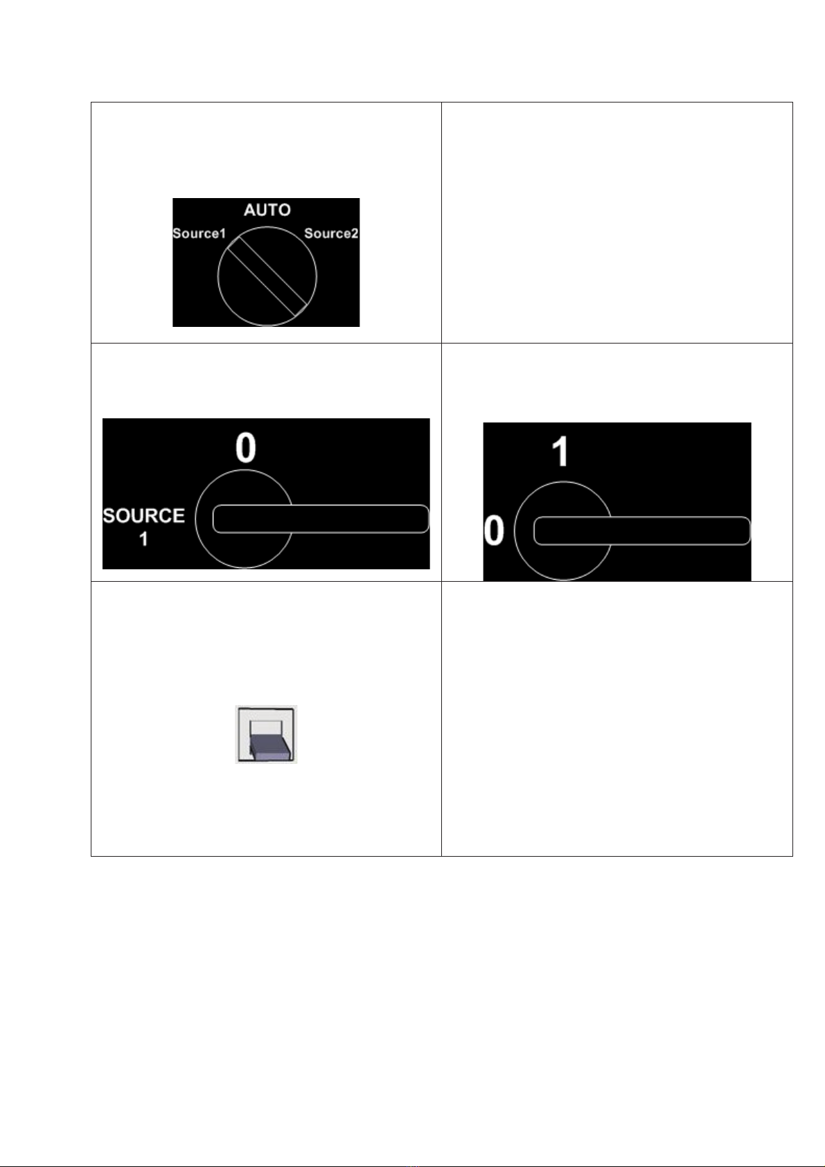
MANUAL TRANSFER SWITCH
Manual transfer switch is located on back front panel and user transfers the load to input source1 or source2
rapidly. During normal operation this switch must be at AUTO position.
Figure – 3 Manuel transfer switch location

- 6 -
SAFETY WARNINGS
IMPORTANT NOTICES
1. This Manual must be carefully read before applying any power to the STS unit.
2. All warnings in the manual should be adhered to.
3. All operating instructions should be followed.
4. The unit should be supplied by a grounded outlet. Do not operate the unit without ground source.
5. Power input cords of the STS should be routed carefully so that they are not to be walked on.
6. Please save this manual.
7. Please save or recycle the packaging materials.
WARNING !!!
•Do not apply electrical power to the STS equipment before arrival of authorized service personnel.
•Installation and commissioning of STS must be performed by a qualified technician.
•Adequate protection against input over currents must be provided, considering the nominal current rating of
the STS.
•Do not insert any object into ventilation holes or other openings.
•To reduce the risk of fire or electric shock, install the unit in temperature and humidity controlled indoor area
free of flammable and corrosive substances.
•The unit have two power inputs ,if one of the supplies is connected risk of electric shock is valid.
•The unit is powered by more than one power mains. When one of the incoming power sources is active, the
unit contains a dangerous level of voltage, even when it is in “MAINTENANCE BYPASS” position
WARNING !!!
•Since it is a high voltage equipment, INFOSTS contains dangerously high voltages. The risk of
contact with these voltages is minimized using a lockable hinged door and internal safety shields in
accordance with IP20 standards.
•All maintenance and installation procedures requiring access to the inside of the device must be
exclusively performed by a trained personnel.
•InfoSTS DOES NOT HAVE AUTOMATIC PROTECTION AGAINST VOLTAGE RETURNING TO THE
INPUT. POWER SWITCHES OR FUSES OUTSIDE THE STS MAY HAVE VOLTAGES ON THEIR
CONNECTION TERMINALS EVEN WHEN THEY ARE TURNED OFF.
•SERVICE PERSONNAL MUST INSULATE THE STS (BY TURNING OF ITS INPUT SWITCHES S1 AND
S2) BEFORE WORKING ON THESE EQUIPMENT.
CAUTION !!!
•Installation and commissioning of this device must be performed by qualified service personnel
trained and authorized by the manufacturer (or distributor)
•Risk of electric shock, do not remove cover. No user serviceable parts inside, refer servicing to
qualified service personnel.
•Risk of electric shock, hazardous live parts inside .

- 7 -
FRONT VIEWS OF THE STS
Interior front view
S6
Manual
transfer
Switch
Dry contact outputs
EPO Input
S3
Output
Switch
S2
Source 2
I/P SW
S1
Source 1
I/P SW
RS232
Port
S4
Maintenance
Bypass
SW
figure - 4

- 8 -
VIEW OF THE CONTROL PANEL
On the front panel of STS there are LEDs, control buttons and a two line alphanumeric LCD display. These
components interact with each other during STS operation. Buttons change menus and submenus on LCD
display. LEDs show the switching position of the STS on a mimic diagram.
figure – 5 STS front panel
On : source 1 is preferred source
1 Source 1 priority lamp Off : source 1 is alternate source
On : source 2 is preferred source
2 Source 2 priority lamp Off : source 2 is alternate source
On: source 1 input is OK
SW1 Source 1 input monitor lamp Off : source 1 input failed
On: source 2 input is OK
SW2 Source 2 input monitor lamp Off : source 2 input failed
On: SS1 SCR group fired
SS1 Source 1 static switch on lamp
S1 static switch on Off : SS1 SCR group open
On: SS2 SCR group fired
SS2 Source 2 static switch on lamp
S6 static switch on Off : SS2 SCR group open
On : output normal
Off : output switch off
SW3 Output monitor lamp
Flash : output voltage inhibit
Flash : previously an alarm occurred
Alarm monitoring lamp Off : there is no alarm on STS
Down button Moves menu item to 1 level down
Enter button Validates the adjusted data or OK confirmation
(+) button Increases the current data
(-) button Decreases the current data

- 9 -
INSTALLATION
ALL THE OPERATIONS DESCRIBED IN THIS SECTION MUST BE CARRIED OUT EXCLUSIVELY BY
QUALIFIED STAFF.
The company may no be held liable for any damage caused by incorrect connections or by operations
that are not described in this manual.
STORAGE OF THE STS
The storage area must have the following characteristics
Temperature : -10 to +50 C
Relative humidity : 95% max.
PREPARATION FOR INSTALLATION
PRELIMINARY INFORMATION
Model STS450 STS4100 STS4150 STS4200 STS4300 STS4400
Nominal current 50 100 150 200 300 400
Operating temperature 0 – 40 C
Non operating temper. -10 to + 50 C
Max. relative humidity 90% (non-condensing) during operation
Max. installation height 1000 m at nominal current rating
Dimensions WxDxH 685x530x1500 mm 685x580x1770 mm
Weight 175 Kg 205 Kg 220 Kg 240 Kg
Protection level IP20
Cable input From base / on front
Communication RS232 standard - TCP/IP option
Flying transfer Available - Standard
LCD panel and mimic Available - Standard
Backfeed protection Available - Standard
Software management Available - Standard
DRY contact outputs Available - Standard
EPO input Available – Standard ( NO)
<X> letter on table shows 3 pole or 4 pole model options ( 3 = 3 pole , 4 = 4 pole )
ELECTROMAGNETIC COMPATIBILITY
This static transfer switch (STS) conforms to the class C2 specifications (in accordance with the provisions laid
down by the EN62040-2 standard: STS – EMC requirement). In the home environment ,it may cause radio
interference. The user may have to take supplementary measures.
This product is designed for professional use in industrial and commercial environments . Connections to the
RS232 connectors should be made with the cables provided or ,in any case, with shielded cables less than 3
meters long.
INSTALLATION ENVIRONMENT
When choosing the site in which to install the STS , the following points should be taken into consideration :
•Avoid dusty environments
•Check that the floor is level and capable of withstanding the weight of the STS
•Avoid cramped environments that could impede the normal maintenance activities
•The relative humidity should not exceed 90%, non-condensing.
•Check that the ambient temperature, with the STS running, remains between 0 and 40 C
•Avoid installing the equipment in places exposed to the direct sunlight and hot air.
REMOVING THE STS FROM PALLET
The STS is packed and enclosed in a structural cardboard carton to protect it from damage.
1. Inspect for damage that may have occurred during the shipment If any damage is noted, call the shipper
immediately and retain the shipping carton and the STS.
2. Carefully open the carton and take the STS out.
Retain the carton and packing material for possible future use

- 10 -
PRELIMINARY CHECK OF CONTENTS
Having opened the package ,start by checking the contents
-User manual
-serial RS232 connection cable
-STS control software and user manual CD
-Guarantee document
INSTALLING THE STS
When installing the equipment the following points should be considered:
•The air outlets of the STS is on the top ,cause of this do not prevent air ventilation from the top side.
•No objects should be left on its top surface
•Sufficient space should be left in front of the equipment for it to be turned on/off and maintenance
operations to be performed on it (>1.5 m)
•Keep out of your equipment from the explosive and flammable items
- 11 -
ELECTRICAL CONNECTIONS
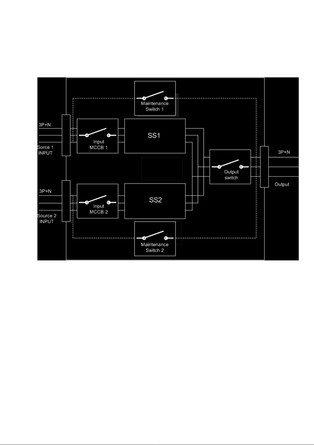
DIAGRAMS OF CONNECTION TO THE ELECTRICAL SYSTEM
WARNING: a 4-wire three-phase distribution system is required for three-phase input and output connections.
The standard version of the STS (3 pole) switches only 3 phases neutral is connected to the output directly. 3-
phase power line + neutral + protective earth (PE), in compliance with the IEC 60364-3 specifications.
Figure – 6 3 pole standard STS input and output block diagram
PROTECTIONS INSIDE THE STS
SHORT CIRCUIT
In the event of a fault on the load , in order to protect itself and the alternate source the STS inhibits the output
voltage. During short circuit event on the load, the connected source to load will be overloaded and the voltage
of this input source will be go down, at this point STS monitors the output current and if current is 200% of
nominal output current , if the input source phase voltages is lower than allowed limit at the same time it decides
that short circuit event occurred at the output of the STS.
At the other hand during over current status , if the input MCCB trips STS decides that short circuit event
occurred at the output of the STS.
OVERLOAD
Electronic overload protection system is used inside of the STS ,this protection system can be enabled or
disable by the user as an option.
BACKFEED
The STS have electronic protection system against backfeed from any input source ,if any backfeed current is
sensed the related input source input MCCB trips.
FUSES
There is no any replacable fuses inside of the STS ,only input MCCB’s protect against overcurrents.

- 12 -
CABLE SIZES
The input/output cables can be sized to suit the STS rating according to the table below
4 pole model 3 pole model Input and output cables Cable type
STS450 STS350 25 mm
2
3 phase+1 neutral +earth
STS4100 STS3100 35 mm
2
3 phase+1 neutral +earth
STS4150 STS3150 50 mm
2
3 phase+1 neutral +earth
STS4200 STS3200 70 mm
2
3 phase+1 neutral +earth
STS4300 STS3300 95 mm
2
3 phase+1 neutral +earth
STS4400 STS3400 120 mm
2
3 phase+1 neutral +earth
NOTE: The neutral conductor should be sized for 1,5 times the output phase current. The Earth conductor
should be sized as 2 times the output conductor (this is dependent on the fault rating, cable lengths,
type of protection etc.) These recommendations are for guideline purposes only and are superceded
by local regulations and codes in practice.
CONNECTIONS
InfoSTS Series Static Transfer Switches run only on 3-Phase AC power supplies with a NEUTRAL line.
The STS unit must be grounded in accordance with electrical regulations
Before making power connections to the unit, ensure that all the incoming power sources are de-energized and
insulated
Cables can enter the InfoSTS from below, through the base panel of the cabinet. Top entry is also possible by
removing the cover panel on the top of the STS revealing the cables entry hole.
The connections of the STS should be supplied by grounded outlets. Cables enter the STS modules via entry
panels in the base of cabinet. All control cables should be screened and run in a separate trunking to the power
cables.

- 13 -
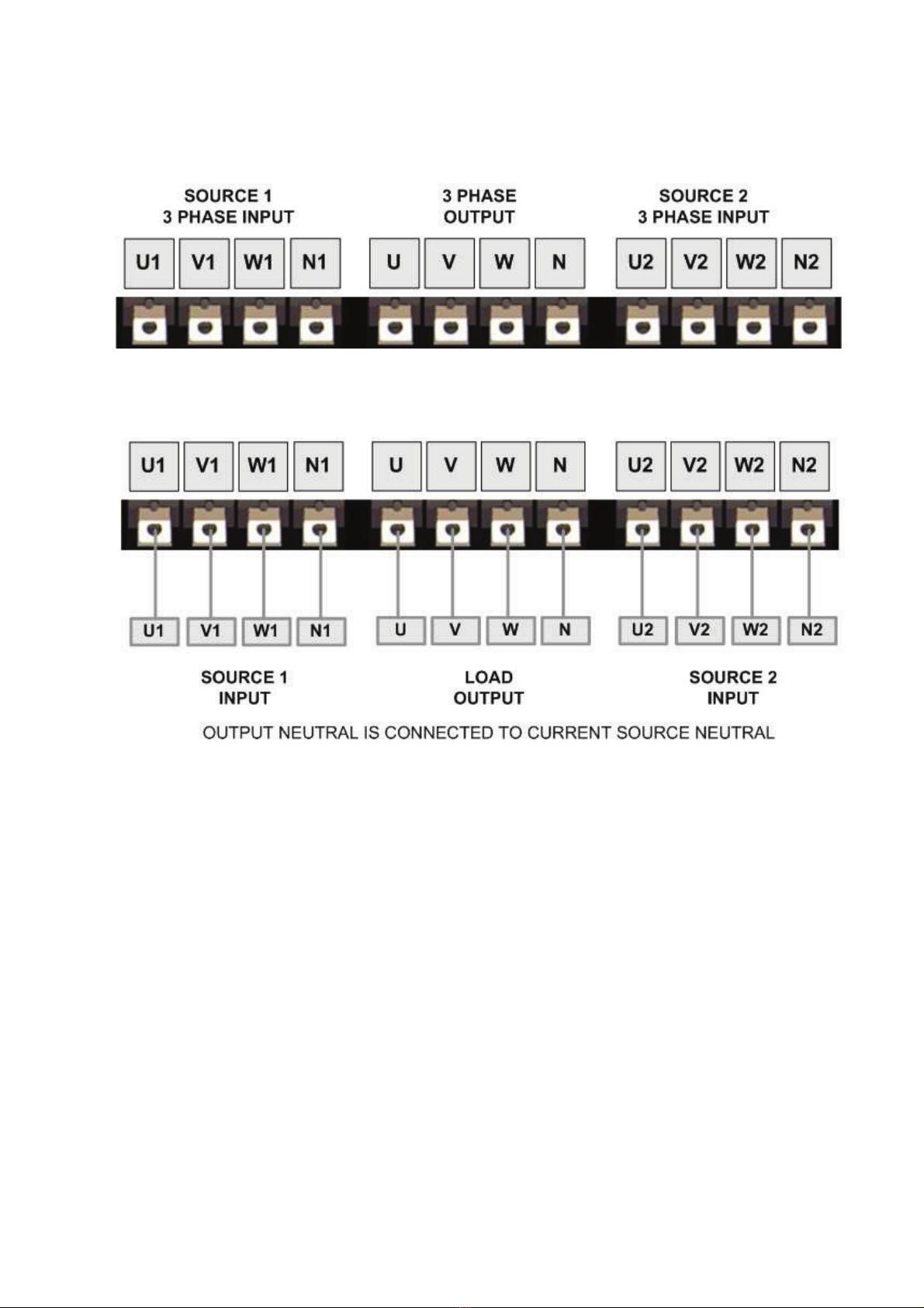
3 POLE STS POWER CONNECTIONS
Input and output terminals of the 3 pole STS are shown in the following figure
figure - 7 Connection terminals of 3 pole STS
figure – 8 3 Pole STS cable connections
- 14 -
4 POLE STS POWER CONNECTIONS
4 pole type STS units connects load output neutral to the current used source’s neutral ,the neutral of the other
source is isolated from output neutral.
Figure - 9 Connection terminals of 4 pole STS
Figure – 10 Input and output cable connections of 4 pole STS
- 15 -
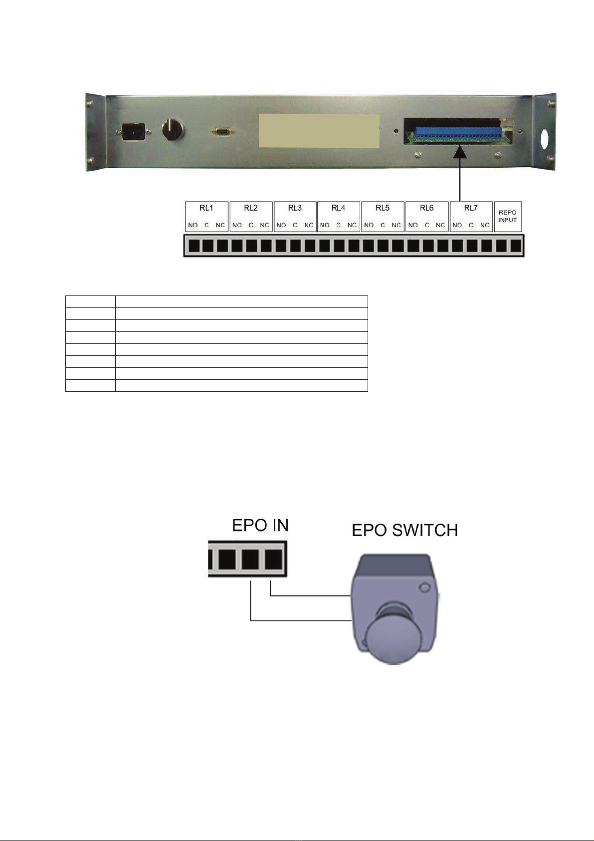
ALARM RELAY CONNECTIONS
Figure - 11 Alarm Relay Contacts and EPO Input Terminals
Relay Function
RL1 Load is connected to alternate input source
RL2 Preferred source indicator relay
RL3 Output Inhibit relay
RL4 Summary alarm relay
RL5 Manual or static transfer relay
RL6 S1 backfeed trip ( 1 second active)
RL7 S2 backfeed trip ( 1 second active)
EPO input is NO type interface (normally open) ,if EPO input terminals shorted to each other STS applies EPO
shutdown procedure.
EXTERNAL EPO BUTTON
figure – 12 Epo input connection
Epo input trips short circuit there is no need to lock EPO signal externally.

- 16 -
WIRING PROCEDURE
1.
Open the STS cabinet front door and remove the metal guard on the lower side to permit access to the
connection terminals and busbars (neutral and earth). Before connecting any power cables, please ensure
that all the circuit breakers on the STS are in “OFF” position. (S1, S2, S3 and S4)
SOURCE 1 Input Power Connections
2.
Connect the SOURCE 1 AC power cables to the terminals U1-V1-W1 of the STS (Figure 7,8,9,10) and
tighten the connections properly.
The neutral cable must be connected to the copper bus-bar identified as “NEUTRAL”.
CHECK FOR CORRECT PHASE ROTATION
SOURCE 2 Input Power Connections
3.
Connect the SOURCE 2 AC power cables to the terminals U2-V2-W2 of the STS (Figure 7,8,9,10) and
tighten the connections properly.
The neutral cable must be connected to the copper bus-bar identified as “NEUTRAL”.
CHECK FOR CORRECT PHASE ROTATION
Output Connections
4.
Connect the output cables to the terminals (U-V-W) of the STS (Figure 7,8,9,10) and tighten the connections
properly.
The output neutral cable must also be connected to the copper bus-bar identified as “NEUTRAL”.
CHECK THAT PHASES ARE CONNECTED IN THE RIGHT ORDER.
CHECK AGAIN ! that U1-U2, V1-V2 and W1-W2 are the corresponding phases of the two separate AC input
sources respectively.
5.
Also proper control and signal wire connections (Alarm relays, EPO etc.) should be made through the screw
terminal block shown in figure 11.
Note : These auxiliary cables must be shielded and double insulated.
(Recommended cross-section 1mm
2
)
6.
Reassemble the metal guard removed previously.
PROTECTIVE EARTH
The protective earth cable must be connected to the earth BUS BAR and bonded to each cabinets in the system
and also the earthing and neutral bonding arrangements must be in accordance with the local laws. Proper
grounding considerably reduces problems in systems caused by electromagnetic interference.
ATTENTION!!! Failure to follow adequate earthing procedures can result in electric shock
hazard to personnel, or the risk of fire
EMERGENCY POWER OFF
This isolated input is used to turn off the STS remotely in case of emergency.
The STS is supplied from the factory with the “Emergency Power Off ” (E.P.O.) terminals open-circuited ( see
“View of the STS connections”) if two (NO) terminals are shorted to each other STS shutdown the output
voltage.
In case of emergency ,by activating the stop device STS enters to stand-by mode and powers off the load
completely.
The E.P.O. circuit is self-powered ,no external power supply voltage is therefore required. If E.P.0. switch
pressed (at least 1 second) STS trips the signal.

- 17 -
USE
DESCRIPTION
The purpose of the STS is to select one of two input power lines which is in tolerant with predefined limits.
Users must decide that one of the input sources must have priority (preferred source) the other source is
alternate source. So the STS tries to stay at priority (preferred) source if this source in tolerant with predefined
values, if this source out of tolerant and the alternate source is in tolerant STS transfers the load to alternate
source. Always STS checks priority (preferred) source if it is in tolerant retransfers the load to priority (preferred)
source.
So before use the STS we must decide that which source is main (preferred) and which source is spare
(alternate).
IMPORTANT : Our STS are designed and produced for long life even under severest conditions. Remember
however that they are electrical power equipment items and as such are in need of periodic checks. Besides,
some components have a life cycle of their own and must therefore be checked at regular intervals and may
need to be replaced, where due to the conditions: in particular fans and some electrolytic capacitors.
It is recommended to implement a preventive maintenance program, using manufacturer authorized and trained
service personnel.
Our Technical Servicing department is at your disposal to discuss the different personalized preventive
maintenance options with you.
PRELIMINARY OPERATIONS
•Visual check of the connections
Check that all the connections have been made strictly following the indications given in the
“Connections” paragraph.
•Check that the following switch positions
S1 – input 1 MCCB 0 position (off)
S2 – input 2 MCCB 0 position (off)
S3 – output switch 0 position (off)
S4 – maintenance bypass switch 0 position (center)
Manual transfer switch auto position (center)
At this point there is no output voltage at the STS output terminals
POWERING ON FOR THE FIRST TIME
•Turn on input 1 power at external input power distribution box (apply power to input 1 terminals) . Measure
the voltages on terminals. (according to your local electricity nominals)
Phase to phase 400 volts AC ,Phase to neutral 230 volts AC.
•Turn on input 2 power at external input power distribution box (apply power to input 2 terminals) . Measure
the voltages on terminals. (according to your local electricity nominals)
Phase to phase 400 volts AC ,Phase to neutral 230 volts AC.
•Optional : If sources are synchronous to each other, Check that the phase sequency is matched between
two input sources (method: measure L1 phase to phase voltage between two sources, repeat this
measurement for L2 and L3 phases if the measured AC voltages is minimum the phases of two input
sources are matched.)
•Turn on S1 (1 position) wait and see the STS control panel activated and shows some messages (source 2
BAD ,output switch off messages are normal)
•Turn on S2 (1 position) wait and see only output switch off message is showed on the control panel.
•At this point according to your application you must select some user options from OPTIONS MENU of the
control panel. You need password to change options. The factory default password is “0000” 4 zeros ,you
can change the factory password after you logged in.(STS front panel functions)
•After you setup some options you can turn on S3 output switch (1 position)
•See that there is no alarm message or alarm sound on the STS
- 18 -
Switching On (Normal Operation) The STS From Off Position
1.
Ensure again that the Maintenance Bypass Switch (S4) is in “0” position and it is locked for safety.
1) Ensure that maintenance bypass switch (S4)
is in 0 position (center)
2) Turn on input switches (1 position) S1 and S2.
The STS control circuits will be energized and
will start functioning.
3) Select your “PREFERRED” source. (Default
factory setting is Source 1). You can change
your selection using the SETTINGS MENU
4) Check from the mimic diagram on the control
panel, that the static switch of the preferred
source is turned on (either SS1 or SS2).
5) Then turn on the output switch S3, to apply
power to the load connected to the output of
the STS
6) See there is no alarm on LCD display
7) STS unit is now ready to use
- 19 -
Switching To Maintenance Bypass Position From Normal (automatic) Operation
1) Select the input source which is going to supply the
load during maintenance, and turn the manual
XFER switch S6 to this selected source (either
Source 1 or Source 2)
2) Follow on the mimic diagram that the load is
switched to the source selected by the manual
XFER switch S6
3) Then turn the Maintenance Bypass Switch (S4) to
the selected source for maintenance. See the
maintenance bypass message on the LCD panel
4) Turn off the output switch S3. This switch
disconnects the static transfer switches SS1 and
SS2 from the STS output, but the load continues to
work on maintenance bypass line
5) Turn off the input switches S1 and S2
6) Now, the unit is ready for maintenance
This manual suits for next models
12
Table of contents
Other inform UPS manuals

inform
inform Informer 1000VA User manual

inform
inform Informer Compact Series User manual

inform
inform GUARDIAN User manual

inform
inform SAVER PLUS DSP SERIES User manual

inform
inform PDSP31010 User manual

inform
inform Pyramid Plus Specification sheet

inform
inform 500 User manual

inform
inform Pyramid DSP T Specification sheet

inform
inform PYRAMID DSP PREMIUM Series User manual

inform
inform Guard 500VA User manual


