INFOSEC P2 SunRise 3000 User manual
User guide______________________2
Notice d’utilisation_______________32
CE certificate / Certificat CE______ 60
2000/3000/4000/5000 W

INFOSEC UPS SYSTEM - 4, rue de la Rigotière - 44700 Orvault - FRANCE - www.infosec-ups.com
Hot Line – Tel + 33 (0)2 40 76 15 82 - Fax + 33 (0)2 40 94 29 51 - hotline@infosec.fr – 04 10 AA 68 203 18
2
User guide
To ensure this product is correctly installed and used appropriately, we highly advise you to
read this user guide very carefully.
1. INTRODUCTION
Thank you for buying this inverter. The P2 SunRise will allow you to convert the solar energy
from the photovoltaic panels into the electrical grid. We hope that this device will get you
satisfied for years. However, it should be mentioned that an inverter is a complex electronic
system which is also confronted with a wide variety of local conditions. If questions arise, do
not hesitate to call your specialized dealer. He will try to help you as quickly and
straightforwardly as possible.
Please read this user's guide carefully to get familiarized with the device. Remember to pay
special attention to the information on installing and commissioning the device.
2. SAFETY INSTRUCTIONS – Security
Risk of Electric Shock:
The inverter unit uses potentially hazardous voltages. Do not attempt to disassemble
this equipment as it does not contain accessible components that can be repaired by
users.
All repairs should be performed by qualified technicians only.
When the inverter is out of order, please refer to section 8: “P2 SUNRISE STATUS
DIAGNOSTICS AND REPAIR” and call the hot line.
Connected products:
When checking the voltage reading, please take into account that solar modules
supply a higher no-load voltage when temperature is low and sunlight level remains
unchanged.
At 14 °F (-10 °C) the open-circuit voltage of the PV modules must never exceed
500 V.
Do not plug the inverter input into its own output socket.
Only appropriately licensed contractors are authorized to connect the P2 SunRise to
the grid. Consult your local authorities for specific requirements. Before connecting the
P2 SunRise to the grid, permission for the connection must be granted by the utility
company.
Good disposals of the device:
The P2 SunRise was not designed for an installation on isolated site (without any
junction box).
Disconnect the inverter from AC power before cleaning with a damp cloth (no
cleaning products).
Do not leave any recipients containing liquid on or near the inverter.
Do not cover the inverter.
CE conformity:
This logo means that this product answers to the LVD and EMC
standards (regarding to the regulation associated with low voltage
safety and the electromagnetic compatibility).

INFOSEC UPS SYSTEM - 4, rue de la Rigotière - 44700 Orvault - FRANCE - www.infosec-ups.com
Hot Line – Tel + 33 (0)2 40 76 15 82 - Fax + 33 (0)2 40 94 29 51 - hotline@infosec.fr – 04 10 AA 68 203 18 3
3. RECYCLING THE USED PRODUCT
P2 SunRise belongs to the electronic and electrical equipment category. At the
end of its useful life, it must be disposed of separately and in an appropriate
manner.
Contact your local recycling or hazardous waste center for information on proper
disposal of the used battery.
4. AFTER-SALES SERVICE
When calling the After-Sales Department, please have the following information ready, it will
be required regardless of the problem: inverter model, serial number and date of purchase.
Please provide an accurate description of the problem with the following details: type of
equipment powered by the inverter, indicator led status, alarm status, installation and
environmental conditions.
You will find the technical information you require on your guarantee or on the identification
plate on the back of the unit. If convenient you may enter the details in the following box.
Model Serial number Date of purchase
P2 SunRise …
! Please keep the original packaging. It will be required in the event the inverter is returned
to the After-Sales Department.

INFOSEC UPS SYSTEM - 4, rue de la Rigotière - 44700 Orvault - FRANCE - www.infosec-ups.com
Hot Line – Tel + 33 (0)2 40 76 15 82 - Fax + 33 (0)2 40 94 29 51 - hotline@infosec.fr – 04 10 AA 68 203 18
4
5. DESCRIPTION
EXTERNAL DIMENSIONS
Model
Dimensions (mm)
P2 SunRise
2000
P2 SunRise
3000
P2 SunRise
4000
P2 SunRise
5000
L 455 455 455 455
H 430 430 510 510
D 190 190 190 190
INFOSEC UPS SYSTEM - 4, rue de la Rigotière - 44700 Orvault - FRANCE - www.infosec-ups.com
Hot Line – Tel + 33 (0)2 40 76 15 82 - Fax + 33 (0)2 40 94 29 51 - hotline@infosec.fr – 04 10 AA 68 203 18 5
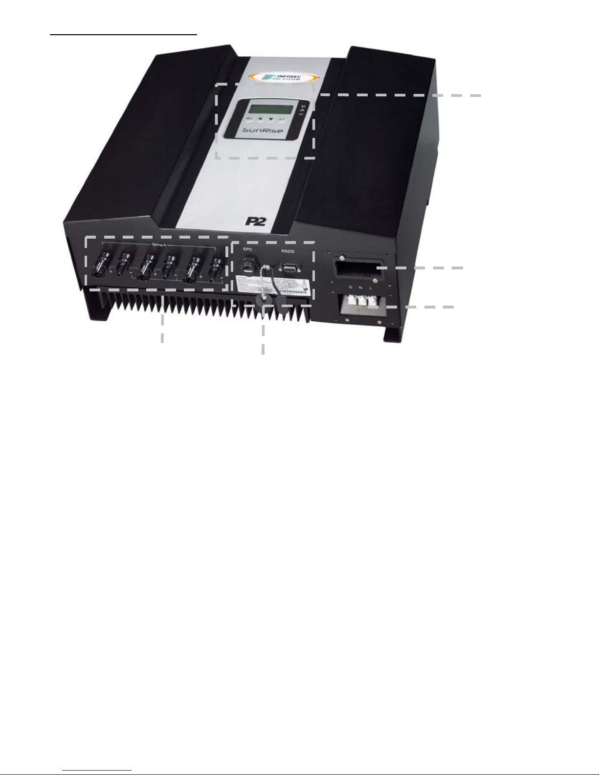
UNIT DESCRIPTION
1 - LEDs and LCD screen: Showing the operation information and status of the inverter.
2 - Solar array input: Plug-and-play terminals for connection of the solar modules.
3 - Standard communication port: EPO & RS232.
4 - Optional communication slot: USB, RS485, dry contact, TCP/IP.
5 - AC output terminal: AC output for the utility supply.
1
2 3
4
5
INFOSEC UPS SYSTEM - 4, rue de la Rigotière - 44700 Orvault - FRANCE - www.infosec-ups.com
Hot Line – Tel + 33 (0)2 40 76 15 82 - Fax + 33 (0)2 40 94 29 51 - hotline@infosec.fr – 04 10 AA 68 203 18
6
4. INSTALLATION
Read the Safety Instruction guide (page 3 to 4) before installing the P2 SunRise.
1. Unpacking
Inspect the P2 SunRise upon receipt. The manufacturer designed robust packaging for your
product. However, accidents and damage may occur during shipment. Notify the forwarder
and dealer if there is damage.
The packaging is recyclable; save it for re-use or dispose of it properly.
Remove the inverter from the carton box.
Check the package contents. Standard content shall include:
1 user’s manual
1 quick install guide
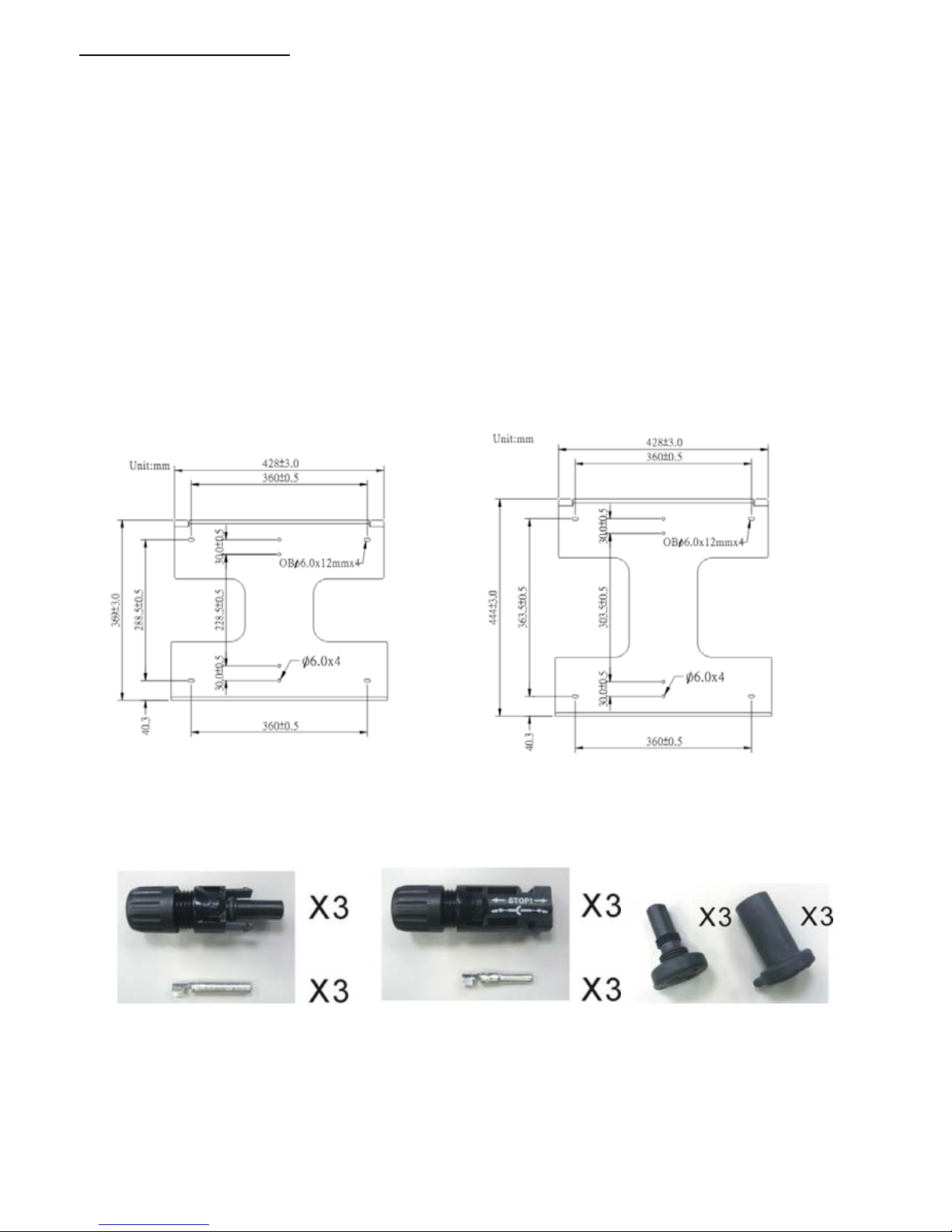
1 set of mounting frame accessories kit as below:
1 set of 18 solar and IP65 waterproof connectors:
P2 SunRise 2000/3000 P2 SunRise 4000/5000 P2 SunRise 4000/5000
INFOSEC UPS SYSTEM - 4, rue de la Rigotière - 44700 Orvault - FRANCE - www.infosec-ups.com
Hot Line – Tel + 33 (0)2 40 76 15 82 - Fax + 33 (0)2 40 94 29 51 - hotline@infosec.fr – 04 10 AA 68 203 18 7
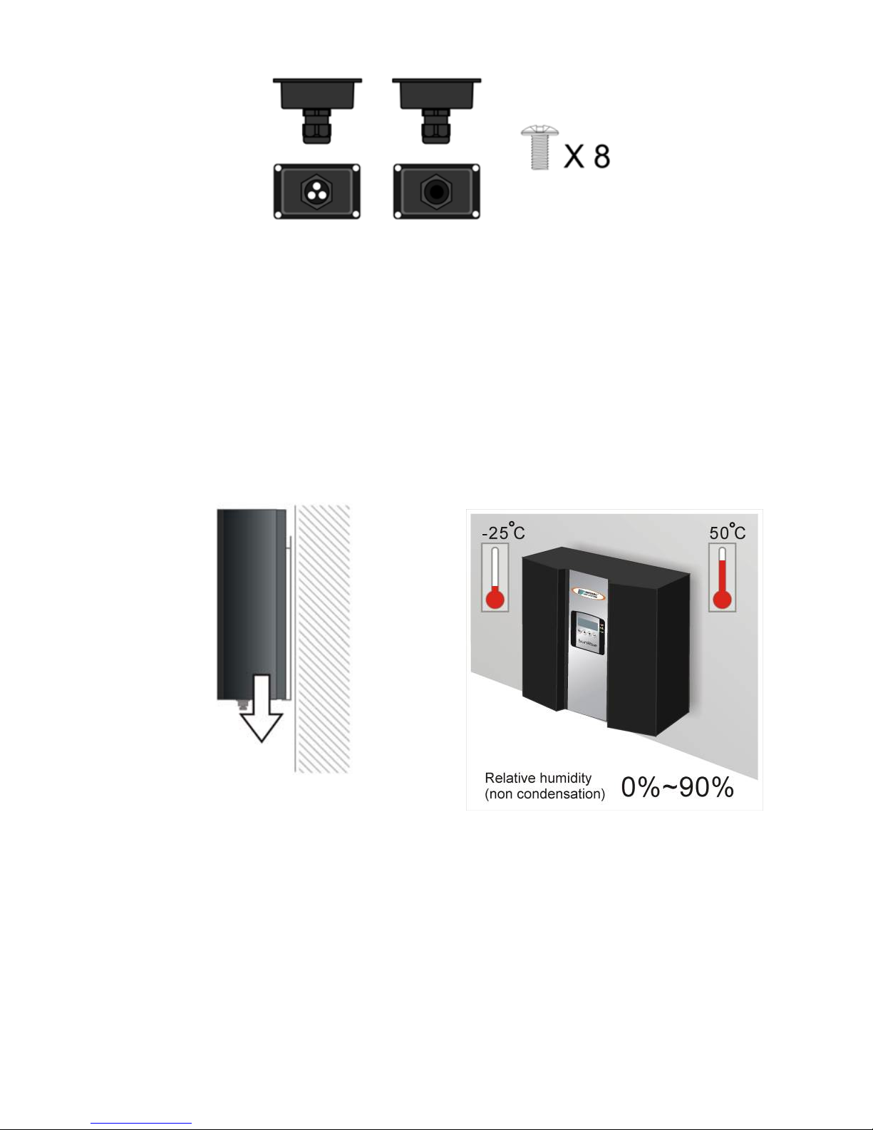
1 set of 2 IP65 waterproof covers with 8 screws:
2. Installation requirements
The P2 SunRise is heavy. Take this weight into account when choosing the installation site
and method of installation.
To ensure proper operation and long operating life, always position the P2 SunRise
according to the following requirement:
(1)The P2 SunRise is designed for indoor and outdoor installations and should be installed
in a place where it is not exposed to direct sunlight. The yield of the PV system may reduce
at increased ambient temperatures or when installed in poorly ventilated and warm indoor
locations. We advise the ambient temperature inside the -25°C to +50 °C range.
P2 SunRise 2000/3000 23KG
P2 SunRise 4000/5000 28KG
INFOSEC UPS SYSTEM - 4, rue de la Rigotière - 44700 Orvault - FRANCE - www.infosec-ups.com
Hot Line – Tel + 33 (0)2 40 76 15 82 - Fax + 33 (0)2 40 94 29 51 - hotline@infosec.fr – 04 10 AA 68 203 18
8
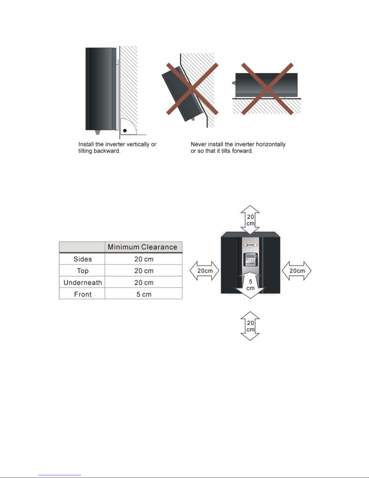
(2) The P2 SunRise is designed to be mounted on a vertical wall. If installing the unit
outdoors, make sure that it is not slanting forward.
We advise against installing the unit in a horizontal position outdoors.
(3) When choosing the installation site, ensure there is enough space for heat dissipation.
Under normal conditions, the following guidelines should be applied for the space to be kept
clear around the inverter:

INFOSEC UPS SYSTEM - 4, rue de la Rigotière - 44700 Orvault - FRANCE - www.infosec-ups.com
Hot Line – Tel + 33 (0)2 40 76 15 82 - Fax + 33 (0)2 40 94 29 51 - hotline@infosec.fr – 04 10 AA 68 203 18 9
3. Mounting the unit
We recommend you to use the supplied wall mounting bracket to mount the P2 SunRise.
For vertical installation and installation on solid concrete or block walls, when selecting the
mounting materials, be sure to take into account the weight of the P2 SunRise.
If you do not want to use the supplied wall mounting bracket as a template, observe the
dimensions shown in page 6. The procedure for mounting the inverter using the wall
mounting bracket is described on the following pages.
INFOSEC UPS SYSTEM - 4, rue de la Rigotière - 44700 Orvault - FRANCE - www.infosec-ups.com
Hot Line – Tel + 33 (0)2 40 76 15 82 - Fax + 33 (0)2 40 94 29 51 - hotline@infosec.fr – 04 10 AA 68 203 18
10
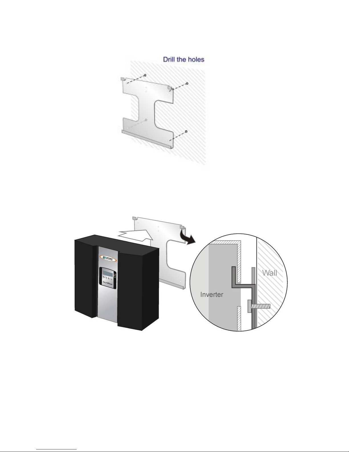
Installation steps
Step 1 - Fit the wall mounting bracket.
To mark the positions to drill the holes, you can use the wall mounting bracket as a drilling
template.
Step 2 - Now hang the P2 SunRise onto the wall mounting bracket using its upper mounting
plate so that it cannot be moved sideways.
Step 3 - Make sure that the P2 SunRise is positioned securely on the bracket.

INFOSEC UPS SYSTEM - 4, rue de la Rigotière - 44700 Orvault - FRANCE - www.infosec-ups.com
Hot Line – Tel + 33 (0)2 40 76 15 82 - Fax + 33 (0)2 40 94 29 51 - hotline@infosec.fr – 04 10 AA 68 203 18 11
4. Installation steps
The complete installation for the P2 SunRise is shown schematically in the following
diagram:
2000/3000
4000/5000
INFOSEC UPS SYSTEM - 4, rue de la Rigotière - 44700 Orvault - FRANCE - www.infosec-ups.com
Hot Line – Tel + 33 (0)2 40 76 15 82 - Fax + 33 (0)2 40 94 29 51 - hotline@infosec.fr – 04 10 AA 68 203 18
12
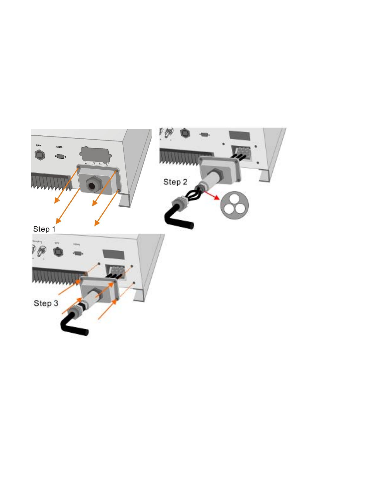
Connecting to the grid (AC utility)
To connect the AC cable, proceed as follows:
Step 1 - Measure grid’s (utility’s) voltage and frequency.
The voltage and frequency of utility are depended on different setting in each country.
Step 2 - Before wiring the PV-Inverter, ensure the main breaker in the primary utility breaker
box is switched OFF. Switch this breaker ON only after all wiring is completed as instructed
in the procedures.
Step 3 - Remove the screws that secure the case of the P2 SunRise and carefully remove
the cover. Remove the connection from the cover as shown here:
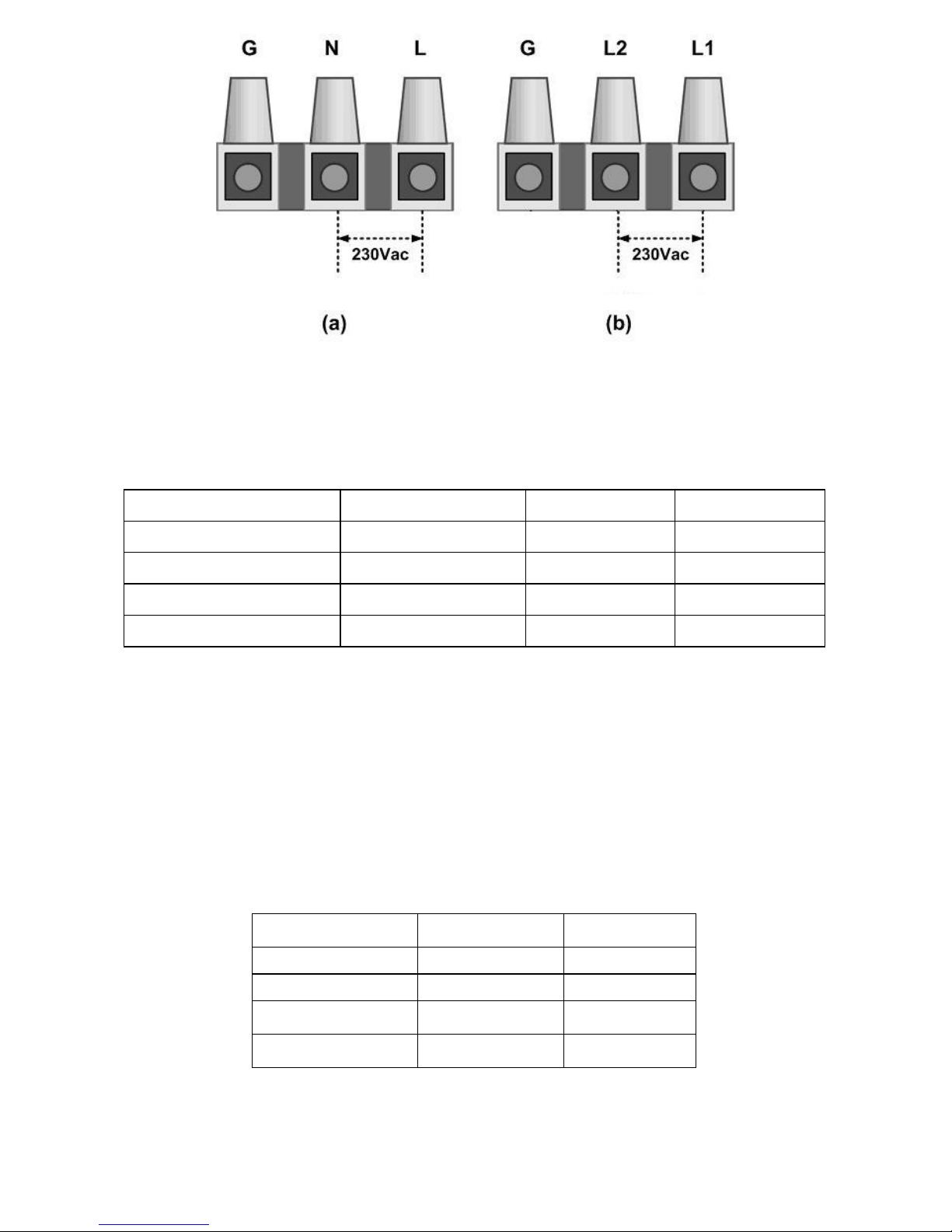
Step 4 - Insert utility wires through cable gland. Connect wires according to polarities
indicated on terminal block.
L1 means LINE1 (black), N means Neutral (White), L2 means LINE2 (Red), G means
system ground (yellow-green) as shown next page:
INFOSEC UPS SYSTEM - 4, rue de la Rigotière - 44700 Orvault - FRANCE - www.infosec-ups.com
Hot Line – Tel + 33 (0)2 40 76 15 82 - Fax + 33 (0)2 40 94 29 51 - hotline@infosec.fr – 04 10 AA 68 203 18 13
Step 5 - Fix the housing cover of the P2 SunRise and evenly tighten the four screws.
To prevent risk off electric shock, ensure the ground wire is properly earthed before
operating the PV Inverter.
※Minimum suggested cable width for AC wire:
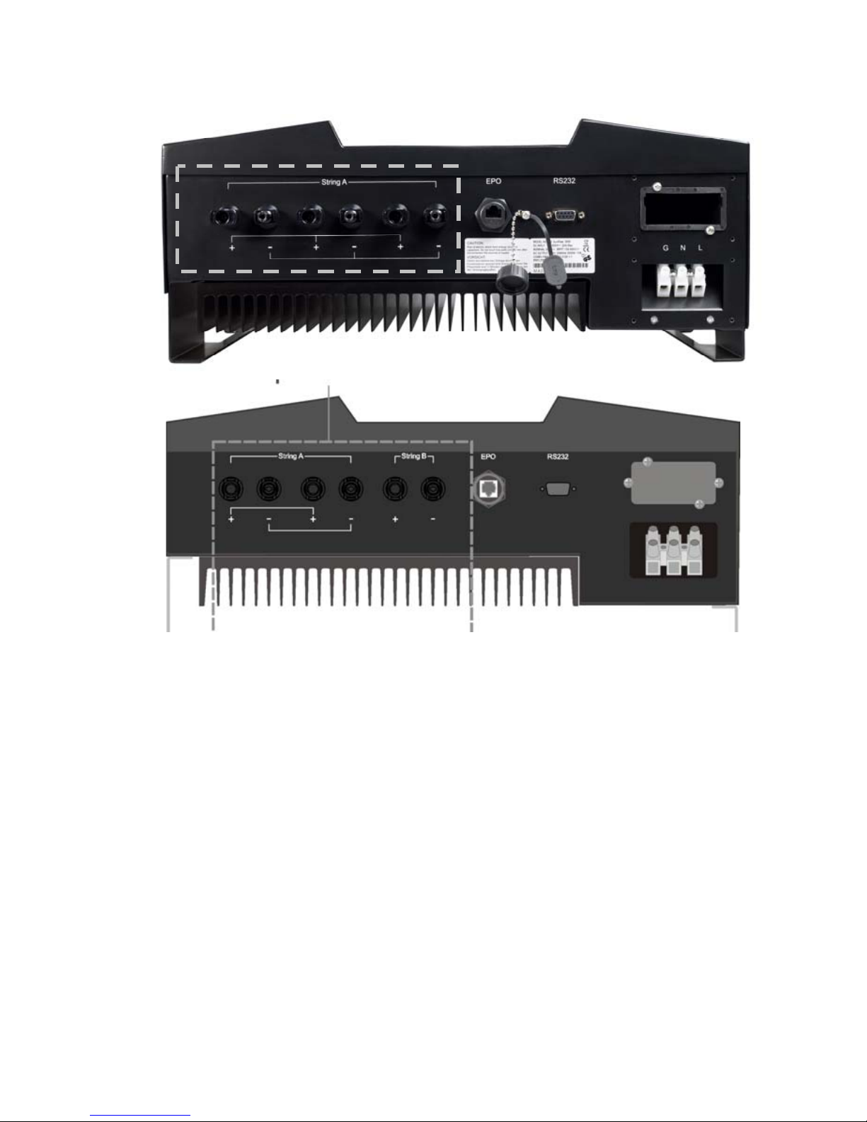
Connecting the PV array (DC)
PV Module requirements
For the P2 SunRise 2000 & 3000 models, all string must be connected to the same PV
panel and number model & number of PV modules with the same orientation (1 MPPT
tracker). For the 4000 & 5000 models, strings can be connected with the same or different
PV module string number to String A and String B (2 MPPT tracker). Those models are also
designed to be connected to two input connector terminals.
※Minimum suggested cable width for DC wire connection:
Model Diameter Φ(mm) Area (mm2) AWG no.
P2 SunRise 2000 >2.05 >3.5 >12
P2 SunRise 3000 >2.05 >3.5 >12
P2 SunRise 4000 >2.59 >5.5 >10
P2 SunRise 5000 >2.59 >5.5 >10
References Diameter Φ(mm) Area (mm²)
P2 SunRise 2000 >2.0 >3.5
P2 SunRise 3000 >2.0 >3.5
P2 SunRise 4000 >2.0 >5.5
P2 SunRise 5000 >2.0 >5.5
INFOSEC UPS SYSTEM - 4, rue de la Rigotière - 44700 Orvault - FRANCE - www.infosec-ups.com
Hot Line – Tel + 33 (0)2 40 76 15 82 - Fax + 33 (0)2 40 94 29 51 - hotline@infosec.fr – 04 10 AA 68 203 18
14
Wiring to PV Module
The P2 SunRise is equipped with PV quick connects for connecting up to two PV strings.
Fig. 4 – PV quick connects
※Guidelines for matching PV array to the P2 SunRise PV-Inverter input.
To determine the number of panels required in the PV string (panels connected in series),
you must ensure that the following three requirements are met:
1. To avoid damage to the inverter, make sure the maximum open circuit voltage
(Voc) of each PV string is less than 500 Vdc under any condition. Voltage over 500
Vdc will damage the inverter.
2. Do not exceed the maximum array short circuit-current rating marked on the
inverter.
3. To achieve maximum energy harvest from your array, ensure that the Vmp (voltage
at maximum power) does not drop below 150 Vdc or increase above 450 Vdc under
most conditions.
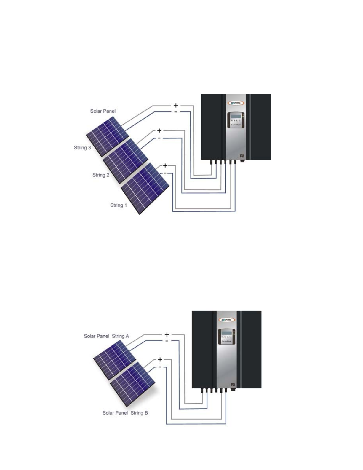
※To wire the PV array to the P2 SunRise Inverter, follow these steps:
Step 1 - Check that the PV generator connectors have the right polarity and do not exceed
the maximum string voltage.
Step 2 - Connect the POSITIVE (+) wire from String 1 to PV1 Inverter positive (+) connect
().
2000/3000
4000/5000
INFOSEC UPS SYSTEM - 4, rue de la Rigotière - 44700 Orvault - FRANCE - www.infosec-ups.com
Hot Line – Tel + 33 (0)2 40 76 15 82 - Fax + 33 (0)2 40 94 29 51 - hotline@infosec.fr – 04 10 AA 68 203 18 15
Step 3 - Connect the NEGATIVE (–) wire from String 1 to PV1 Inverter negative (–) connect
().
Step 4 - Connect the GND wire from String 1 to PV Inverter GND connect.
Step 5 - If necessary, repeat step 2 and Step 4 for String 2 (& ). Double checks that the
wires are in the proper locations.
Step 6 - If necessary, repeat step 2 and Step 4 for String 3 (& ). Double checks that the
wires are in the proper locations.
P2 SunRise 4000 & 5000
Configuration n°1: 2 different Strings
2000/3000
*String Solar panel of string 1 equal string 2 equal string 3
4000/5000
INFOSEC UPS SYSTEM - 4, rue de la Rigotière - 44700 Orvault - FRANCE - www.infosec-ups.com
Hot Line – Tel + 33 (0)2 40 76 15 82 - Fax + 33 (0)2 40 94 29 51 - hotline@infosec.fr – 04 10 AA 68 203 18
16
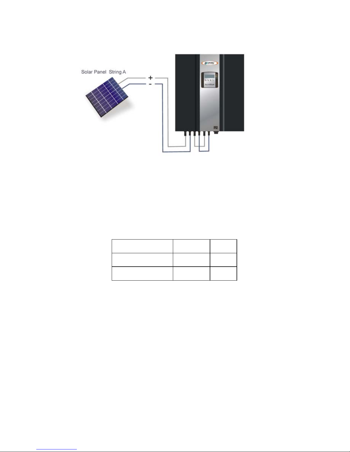
P2 SunRise 4000 & 5000
Configuration n°2: 1 String
In case of one unique String of 4 or 5 kW, you must shunt the String A and B connexions
and set those in parallel mode (please refer to the Setting Mode guide).
※New width of the CC cables:
Reference Diameter Width
P2 SunRise 4000 >4.0 >7.0
P2 SunRise 5000 >4.0 >7.0
4000/5000
Solar panel of string A equal or unequal String B.
INFOSEC UPS SYSTEM - 4, rue de la Rigotière - 44700 Orvault - FRANCE - www.infosec-ups.com
Hot Line – Tel + 33 (0)2 40 76 15 82 - Fax + 33 (0)2 40 94 29 51 - hotline@infosec.fr – 04 10 AA 68 203 18 17
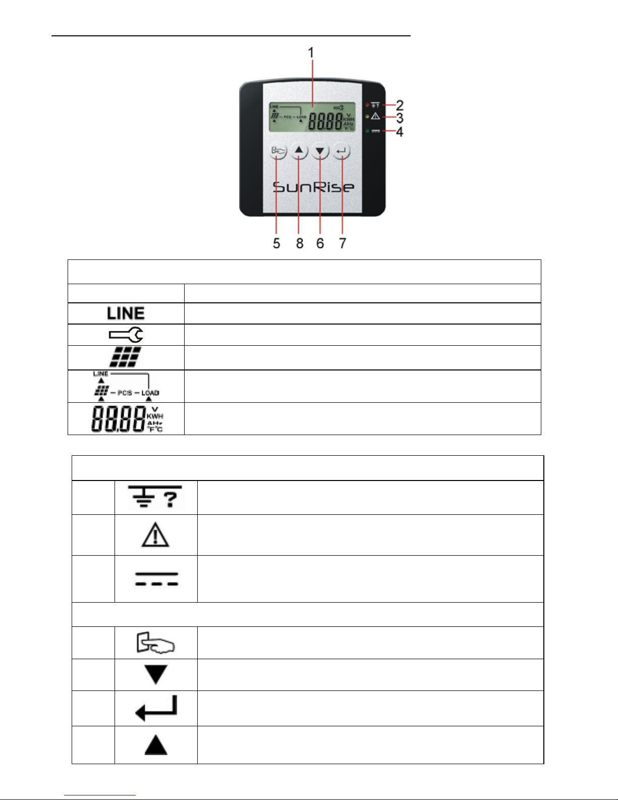
5.FRONT PANEL FUNCTIONAL DESCRIPTIONS
1- LCD Display
Symbol Description
Utility Source
Inverter Working in specified mode
Solar Cell
Inverter operation mode Flow Chart
4 Digits Measurement Display
LED Indicators
2
RED LED steadily li
g
hts up to indicate that the Ground fault or DC
input isolation fault.
3
YELLOW LED steadily lights up to indicate that the utility (ex.
Volta
g
e, frequency etc.) is not matches with the input standard of
the inverter.
4
Green LED steadily li
g
hts up to indicate that the Solar Cell power is
g
reater than sleep power; the LED flashes flickerin
g
ly to indicate that
the Solar Cell power is smaller than sleep power.
Control Keypads
5Special Function Log in /out
6Go to next page.
7To re-confirm the change of Inverter Setting
8Go to previous page.
INFOSEC UPS SYSTEM - 4, rue de la Rigotière - 44700 Orvault - FRANCE - www.infosec-ups.com
Hot Line – Tel + 33 (0)2 40 76 15 82 - Fax + 33 (0)2 40 94 29 51 - hotline@infosec.fr – 04 10 AA 68 203 18
18
6. STARTING THE P2 SUNRISE
Before the inverter is started, be Ensure as follow:
ĞThe housing cover is securely screwed tight.
ĞEnsure the AC breaker is OFF.
ĞEnsure the DC cables (PV strings) are fully connected.
ĞEnsure the AC (utility) cable is connected correctly.
1. Operations test and installation instruction
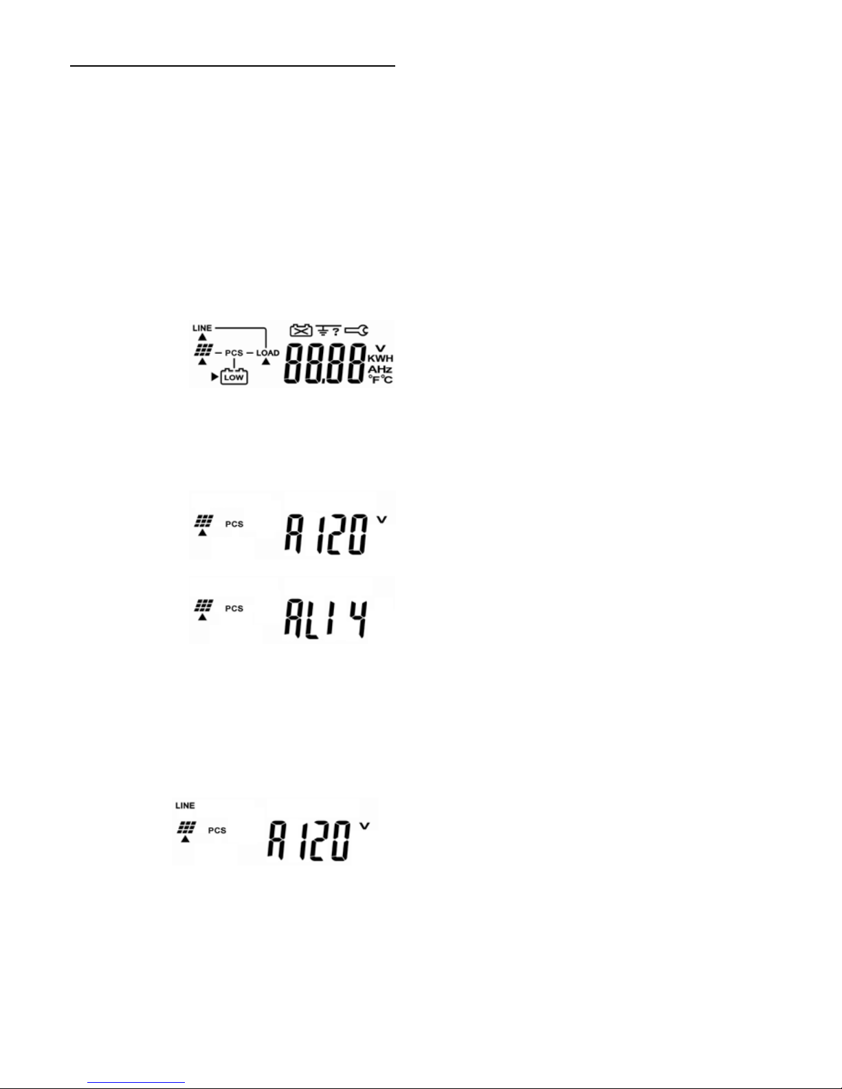
1 - Connect the PV string voltage by switching on the DC circuit breaker. The Inverter starts
automatically when it receives DC voltage greater than 120Vdc. All of the LEDs will light up.
The LCD display will illustrate drawing A.
A
2 - After 3 seconds, the LCD display will illustrate from drawing A to drawing B1 and B2. The
Green LED flashes flickeringly to indicate that the DC input power is smaller than sleep
power. The yellow LED steadily lights up to indicate that no utility exists.
B1
B2
3 - Turn on the AC breaker. If Utility specification (ex. Voltage, frequency etc.) is matched
with the specs of the inverter, after 300 seconds the LCD display will illustrate drawing C.
And the Yellow LED will go out to indicate that the utility is acceptable by the inverter. If
Utility’s specification (ex. Voltage, frequency etc.) is not matched with the specs of the
inverter then an error code or error status will be shown on the screen.
C
INFOSEC UPS SYSTEM - 4, rue de la Rigotière - 44700 Orvault - FRANCE - www.infosec-ups.com
Hot Line – Tel + 33 (0)2 40 76 15 82 - Fax + 33 (0)2 40 94 29 51 - hotline@infosec.fr – 04 10 AA 68 203 18 19
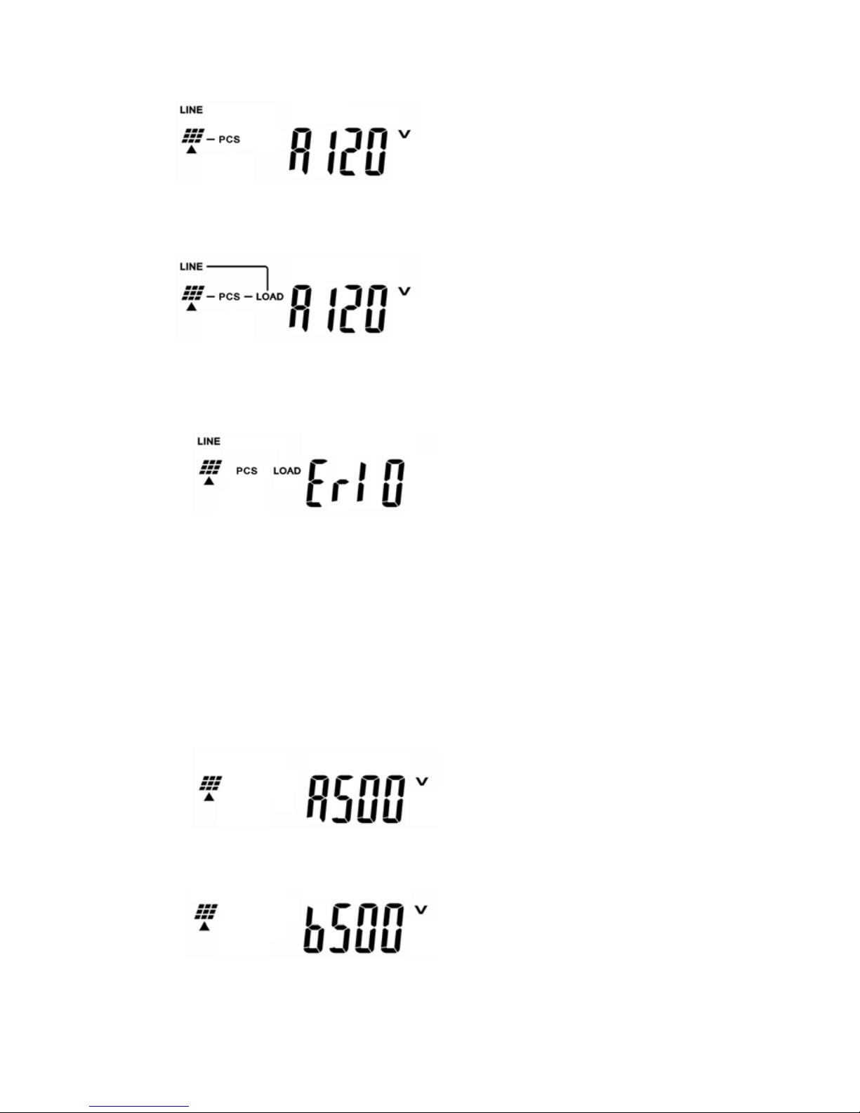
4 - After 5 seconds, if the DC soft start of the inverter is successful, the LCD display will
illustrate drawing D. The Green LED still flashes flickeringly.
D
5 - After 10 seconds, if the AC soft start of inverter is successful the LCD display will
illustrate drawing E.
E
6 - If the inverter is in failure (ex. Output Current Over Range), then an error code or error
status will be shown on the screen. (Ex: Drawing F)
F
7 - If start-up operation of the inverter is completely and successful. The LCD display will
illustrate drawing E.
2. Check measured values & figures detected by the P2 SunRise
If you would like to check the measured values & figures detected by the Inverter, please
use scroll up and scroll down key pads. When you use scroll down key pad, the LCD display
will illustrate as:
1 - Input DC voltage of String A, as drawing G.
G
2 - Input DC voltage of String B, as drawing H.
H

INFOSEC UPS SYSTEM - 4, rue de la Rigotière - 44700 Orvault - FRANCE - www.infosec-ups.com
Hot Line – Tel + 33 (0)2 40 76 15 82 - Fax + 33 (0)2 40 94 29 51 - hotline@infosec.fr – 04 10 AA 68 203 18
20
3 - Input DC current of String A, as drawing I.
I
4 - Input DC current of String B, as drawing J.
J
5 - Output power of booster A, as drawing K.
K
6 - Output power of booster B, as drawing L.
L
7 - Output voltage of inverter (utility voltage), as drawing M.
M
8 - Output frequency of inverter (utility frequency) , as drawing N.
N
9 - Output current supplied to load, as drawing O.
O
This manual suits for next models
3
Table of contents
Languages:
Other INFOSEC Inverter manuals

Popular Inverter manuals by other brands

Felicitysolar
Felicitysolar SCHM Series user guide

Agilent Technologies
Agilent Technologies 33220A user guide

Epever
Epever NPower Series user manual

IOTA
IOTA IIS3P Series installation guide

Northern Lights
Northern Lights Lugger OM673 Operator's manual

Northern Lights
Northern Lights NL1064D, NL1064T1, NL1064T2, NL1064H1, NL1066T, NL1066H1, NL1066H2, and... Operator's manual


