INHENERGY SI-3.6K-S2 User manual

INHENERGY CO., LTD.
User Manual
SI-3.6K-S2, SI-4K-S2, SI-4.6K-S2, SI-5K-S2, SI-6K-S2

-1-
CONTENTS
1 NOTES ON THIS MANUAL...........................................................................................................- 3 -
1.1 VALIDITY................................................................................................................................... - 3 -
1.2 SYMBOLS IN THIS DOCUMENT.......................................................................................... - 3 -
2 OVERVIEW.......................................................................................................................................- 5 -
2.1 PRODUCT INTRODUCTION................................................................................................. - 5 -
2.2 APPEARANCE..........................................................................................................................- 5 -
3 INSTALLATION................................................................................................................................- 6 -
3.1 CHECK FOR PHYSICAL DAMAGE...................................................................................... - 6 -
3.2 PACKING LIST..........................................................................................................................- 6 -
3.3 MOUNTING............................................................................................................................... - 7 -
3.4 SPACE REQUIREMENT......................................................................................................... - 9 -
3.5 MOUNTING STEPS.................................................................................................................- 9 -
4 ELECTRICAL CONNECTION.....................................................................................................- 10 -
4.1GRID CONNECTION..............................................................................................................- 10 -
4.2 EARTH CONNECTION......................................................................................................... - 12 -
4.3 PV CONNECTION................................................................................................................. - 12 -
4.4 WIFI/GPRS CONNECTION................................................................................................. - 14 -
4.5 TURN-OFF THE INVERTER................................................................................................ - 14 -
5 POWERING ON THE SYSTEM.................................................................................................. - 14 -
5.1 START-UP THE INVERTER................................................................................................. - 14 -
5.2 FIRST RUN TIME SETTING................................................................................................ - 14 -
6 LCD OPERATION......................................................................................................................... - 14 -
7 MAINTENANCE AND CLEANING.............................................................................................- 16 -
7.1 MAINTAIN PERIODICALLY..................................................................................................- 16 -
7.2 TROUBLE SHOOTING......................................................................................................... - 16 -

User Manual
-2-
8 DECOMMISSIONING................................................................................................................... - 17 -
8.1 REMOVE THE INVERTER................................................................................................... - 17 -
8.2 PACKAGING........................................................................................................................... - 17 -
8.3 STORAGE AND TRANSPORTATION.................................................................................- 17 -
9 TECHNICAL DATA....................................................................................................................... - 18 -
10 MANUFACTURER WARRANTY..............................................................................................- 19 -
11 CONTACT.....................................................................................................................................- 19 -
-3-
1 Notes on this manual
1.1 Validity
This manual describes the assembly, installation, commissioning and maintenance of the
following Inhenergy Inverter model:
SI-3.6K-S2,SI-4K-S2,
SI-4.6K-S2,SI-5K-S2,
SI-6K-S2;
Target Group
This manual is for qualified personnel. Qualified personnel have received training and
have demonstrated skills and knowledge in the construction and operation of this device.
Qualified Personnel are trained to deal with the dangers and hazards involved in
installing electric devices.
Additional information
Find further information on special topics in the download area at www.inhenergy.com
The manual and other documents must be stored in a convenient place and be available
at all times. We assume no liability for any damage caused by failure to observe these
instructions. For possible changes in this manual, Inhenergy Co., Ltd. accepts no
responsibilities to inform the users.
1.2 Symbols in this document
Please pay close attention to all the symbols for the purpose of avoiding possible personal
injury or equipment break down.
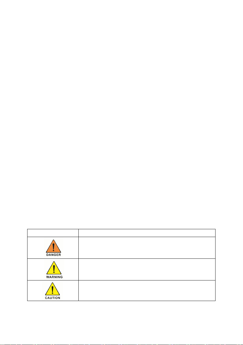
Symbol
description
DANGER indicates a hazardous situation which, if not avoided,
will result in death or serious injury.
WARNING indicates a hazardous situation which, if not avoided,
could result in death or serious injury.
CAUTION indicates a hazardous situation which, if not avoided,
could result in minor or moderate injury.
User Manual
-4-
Markings on this product
NOTICE is used to address practices not related to personal
injury
Information that you must read and know to ensure optimal
operation of the system.
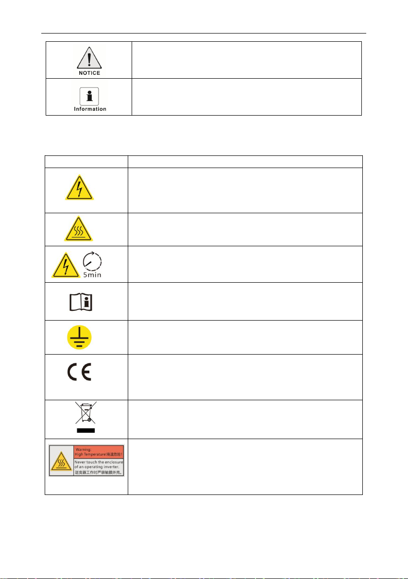
Symbol
Explanation
Caution,risk of electric shock
Caution,hot surface
Operation after 5 minutes
Read the manual
Point of connection for grounding protection
CE mark.
The inverter complies with the requirements of the applicable CE
guidelines.
The inverter must not be disposed of with the household waste.
Burn warning
Do not touch an operating inverter because it generates high
temperatures on the shell.

User Manual
-5-
2 Overview
2.1 Product Introduction
Function
The Inverters is a single-phase grid-tied PV string inverter that converts the DC power
generated by PV strings into AC power and feeds the power into the power grid.
Models
This document involves the following product models:
SI-3.6K-S2,SI-4K-S2,SI-4.6K-S2,SI-5K-S2,SI-6K-S;
Model description (SI-6K-S2 is used as an example)
Model description
2.2 Appearance
①LED indicator ②Function button ③LCD display ④DC switch ⑤DC input terminals(PV1)
⑥DC input terminals(PV2)⑦CT ⑧GPRS/WIFI output port ⑨AC output port
Icon
Meaning
Description
1
Product
the grid-tied PV string inverter
2
Power level
3.6K :The rated power is 3.6 kW.
4K :The rated power is 4 kW.
5K :The rated power is 5 kW.
6K :The rated power is 6 kW.
3
Product code
S2: Second generation product of single-phase
inverter

User Manual
-6-
LED indicator description
Function button description
3 Installation
3.1 Check for Physical Damage
Make sure the inverter is intact during transportation. If there is any visible damage, such as
cracks, please contact your dealer immediately.
3.2 Packing List
Open the package and take out the product, please check the accessories first.
The packing list shown as below.
Category
Status
Meaning
Blinking green at short intervals
waiting status
Blinking green at long intervals
Self-check
Steady green
normal status
Blinking red at short intervals
Alarm
Steady red
Fault
Off
faultless
Status
Description
Short press (0.5s)
Down:Move cursor to downside or decrease value
Long press (2s)
Enter:Confirm the selection.

User Manual
-7-
3.3 Mounting
Installation Precaution
SI-6-S2 Series inverter is designed for outdoor installation (IP 65).
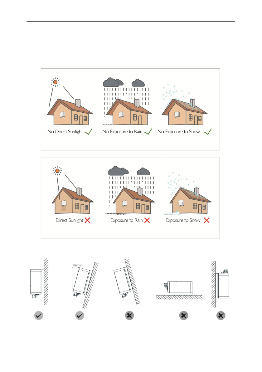
Make sure the installation site meets the following conditions:
◆Not in direct sunlight.
◆Not in areas where highly flammable materials are stored.
◆Not in potential explosive areas.
◆Not in the cool air directly.
◆Not in environment of precipitation or humidity (>95%).
◆Under good ventilation condition.
◆The ambient temperature in the range of -20℃to +60℃.
◆The wall hanging the inverter should meet conditions below:
Object
Description
Quantity
A
Inverter
1
B
Bracket
1
C
AC connector
1
D
PV connectors (2*positive, 2*negative)
2/2
E
PV pin connectors (2*positive, 2*negative)
2/2
F
Expansion tubes/Set screw
3/3
G
Set screw( for mounting)
2
H
User manual
1
I
Wifi/GPRS module (optional)
1
J
CT connectors (optional)
1
User Manual
-8-
1.Solid brick/concrete, or strength equivalent mounting surface;
2.Inverter must be supported or strengthened if the wall’s strength isn’t enough(such as
wooden wall, the wall covered by thick layer of decoration).
Please avoide direct sunlight, rain exposure, snow laying up during.
◆The slope of the wall should be within 15°.
User Manual
-9-
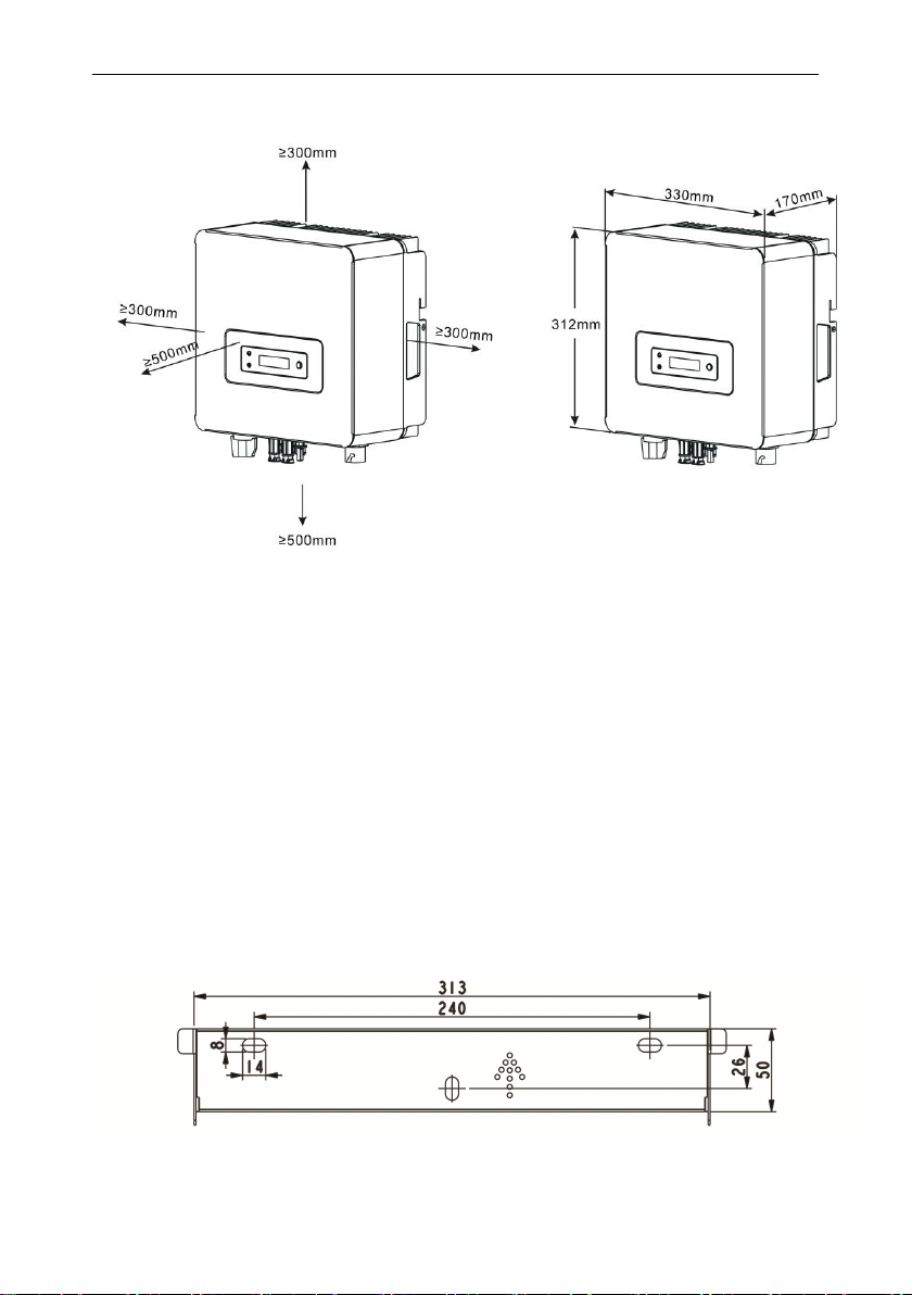
3.4 Space Requirement
3.5 Mounting Steps
1.Use the wall bracket as a template to mark the position of the 3 holes on the wall.
2.Drill holes with driller, make sure the holes are deep enough (at least 60mm) for
installation, and then tighten the expansion tubes.
3. Install the expansion tubes in the holes, and tighten them. Then install the wall
bracket by using the expansion screws.(Φ10 driller, torque: 2.5±0.2Nm)
4. Hang the inverter over the bracket, move the inverter close to it, slightly lay down the
inverter, and make sure the 3 mounting bars on the back are fixed well with the 3
grooves on the bracket.
5.After confirming the inverter is fixed reliably, fasten two M5 safety-lock sockets head
cap screws on the right or left side firmly to prevent the inverter from being lifted off the
bracket (torque: 2.0±0.2Nm)

User Manual
- 10 -
4 Electrical Connection
4.1Grid Connection
SI-6K-S2 Series inverter are designed for single phase grid. Voltage is 220/230/240V,
frequency is 50/60Hz. Other technical requests should comply with the requirement of the
local public grid.Micro-breaker should be installed between inverter and grid, any load should
not be connected with inverter directly.
User Manual
- 11 -
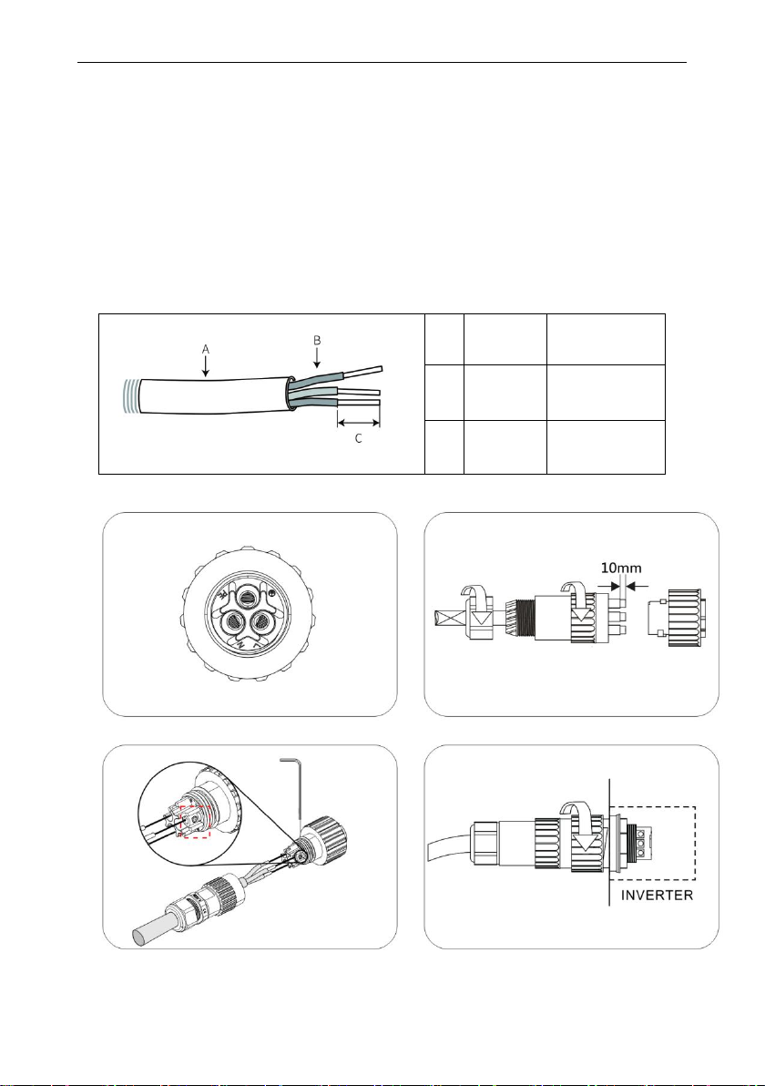
Connection Steps
1. Choose the appropriate wire(Cable size: refer to Table3).
2.Remove 10mm of insulation from the end of wire.
3.Thread cables through pressure screw, seal ring, threaded sleeve in sequence.
4. insert the stripped and bared conductors L,N,PE into the screw terminals with sign L ,
N ,PE on the socket element and tighten the screws firmly.
5.Plug the socket into AC output terminal,clockwise rotation to tighten the socket.
Table 3 Cable recommended
A
Diameter
10-14mm
B
Area
4-6mm²
C
Length
10mm
User Manual
- 12 -
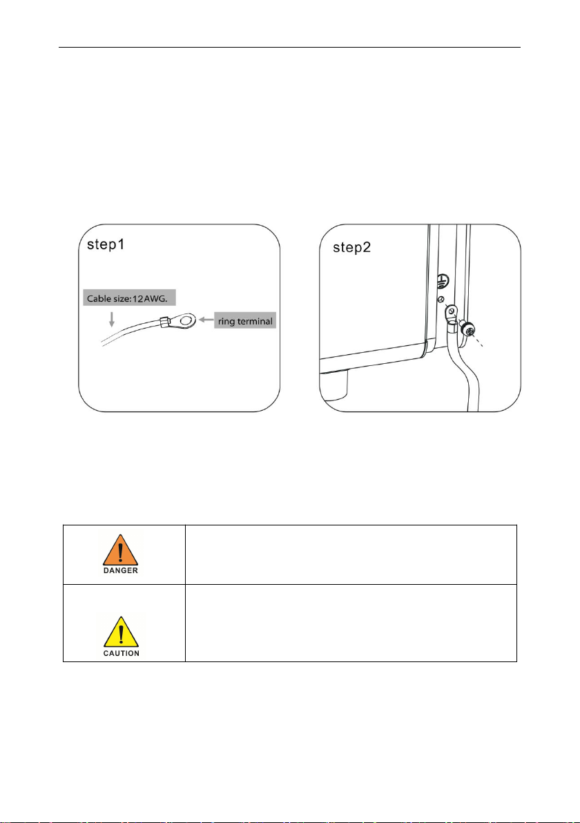
4.2 Earth Connection
Users must addtionally earth the inverter to the enclosure of a second earthing or
equipotential bonding. This prevents electric shock if the original protective conductor fails.
Earth Connection Steps:
1. Strip the earthing cable insulation and insert the stripped cable into the ring terminal, then
clamp it .
2. Place the ring terminal into the earthing rod and screw the earthing screw tightly.
4.3 PV connection
◆Conditions for DC Connection
The inverter has 1 independent input . Notice that the connectors are in paired (male and
female connectors). The connectors for PV arrays and inverters are H4 connectors;
◆Connecting the PV Array
The solar modules connected to the inverter must conform to the
Class A requirements of the IEC 61730 standard.
If the inverter is not equipped with a DC switch but this is mandatory in the
country of installation, install an external DC switch.The following limit
values at the DC input of the inverter must not be exceeded 12.5A

User Manual
- 13 -
Connection Steps:
1. Choose the 12 AWG wire to connect with the cold-pressed terminal.
2. Remove 7mm of insulation from the end of wire.
3. Insert the insulation into pin contact and use crimping plier to clamp it.
4. Insert pin contact through the cable nut to assemble into back of the male or female plug.
When you feel or heard a “click” sound the pin contact assembly is seated correctly.
5. Plug the PV conntector into the corresponding PV connector on inverter.
4.4 WiFi /GPRS Connection(optional)
Inverter provides a WiFi/GPRS port ,which can collect data from inverter and transmit it to
monitoring-website via a WiFi/GPRS module.
Please refer to the accessory manual for specific configuration.
1. Align the serial port of the WiFi/GPRS module with the inverter and plug it in tightly.
2.Fasten the WiFi/GPRS module to the inverter with the screw..
Danger to life due to lethal voltages!
◆PV array supplies d.c voltage to inverter when exposed to light,before
connecting the PV array, cover some light screens above PV
arrays,ensure that the DC switch and AC breaker are disconnect from the
inverter. NEVER connect or disconnect the DC connectors under load.
◆Make sure the maximum open circuit voltage(Voc) of each PV string is
less than the maximum input voltage of the inverter.
◆Check the design of the PV plant. The Max. open circuit voltage, which
can occur at solar panels temperature of -10℃, must not exceed the Max.
input voltage of the inverter.
◆Improper operation during the wiring process can cause fatal injury to
operator or unrecoverable damage to the inverter. Only qualified
personnel can perform the wiring work.
◆Please don’t connect PV array positive or negative pole to the ground, it
couldcause serious damages to the inverter
◆Check the connection cables of the PV modules for correct polarity and
make sure that the maximum input voltage of the inverter is not exceeded.

User Manual
- 14 -
4.4 Turn-off the Inverter
Turn-off the inverter step:
1.Disconect the line circuit breaker from single-phases grid and prevent it from being
reactivated.
2.Turn off the dc switch.
3.Check the inverter operating status.
4.Waiting until LED, OLED have go out, the inverter is shut down.
5 Powering On the System
5.1 Start-Up the inverter
1.Turn on the AC switch between the inverter and the power grid.
2. If there is a DC switch between the PV string and the inverter, turn on the DC switch.
3. Turn on the DC switch at the bottom of the inverter.
4. Observe the LEDs to check the operating status of the inverter.
5.2 First run time setting
When the inverter is used for the first time, please set the time first. The set time is the
same as the current time, and confirm to save.
Do not disconnect the DC connectors under load.
Before turning on the AC switch between the inverter and the
power grid, use a multimeter set to the AC position to check
that the AC voltage is within the specified range.

User Manual
- 15 -
6 LCD Operation
The main interface is the default interface, the inverter will automatically jump to this interface
when the system started up successfully or not operated for a period of time.
Menu interface
User Manual
- 16 -
7 Maintenance and Cleaning
7.1 Maintain Periodically
1.Checking Heat Dissipation
If the inverter regularly reduces its output power due to high temperature, please improve the
heat dissipation condition. Maybe you need to clean the heat sink.
2. Cleaning the Inverter
If the inverter is dirty, turn-off the AC breaker and DC switch ,waiting the inverter shut
down ,then clean the enclosure lid, the display, and the LEDs using only a wet cloth. Do not use
any cleaning agents (e.g. solvents or abrasives)
3. Checking the DC switch
Check for externally visible damage and discoloration of the DC switch and the cables at
regular intervals.If there is any visible damage to the DC switch, or visible discoloration or
damage to the cables, contact the installer.
7.2 Trouble shooting
Our quality control program assures that every inverter is manufactured to accurate
specifications and is thoroughly tested before leaving our factory. If you have difficulty in the
operation of your inverter, please read through the following information to correct the problem.
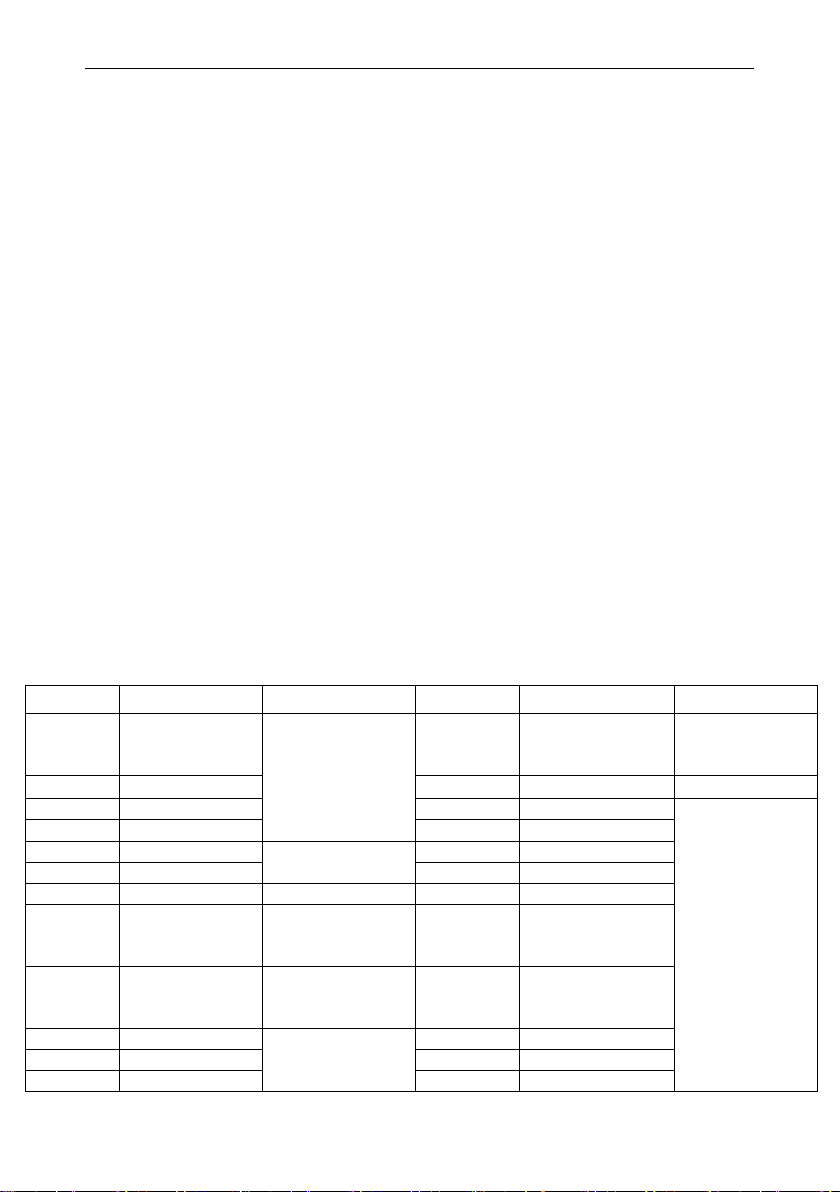
Alarm ID
Alarm Name
Suggestion
Alarm ID
Alarm Name
Suggestion
E0
Grid Volt Low
Check the AC
voltage frequency
range
E16
Remote Off
Check
background
instructions
E1
Grid Volt High
E17
Reserved
E2
Grid Freq Low
E18
SPI Comm. Fault
Restart the
inverter, if the
fault does not
disappear,
contact the
manufacturer
E3
Grid Freq High
E19
Reserved
E4
Bus Volt Low
Check PV input
voltage range
E20
GFCI over Fault
E5
Bus Volt High
E21
GFCI Dev. Fault
E6
Reserved
E22
Volt Cons Fault
E7
Isolation Fault
Check PV
impedance to
ground
E23
Curr inconsiste
E8
Input Curr Over
Check the PV
panel
configuration
E24
Freq inconsiste
E9
Hard Curr Over
Restart the
inverter, if the fault
does not
E25
GFCI inconsiste
E10
Inv Curr Over
E26
Softstart fail
E11
Inv DCI Over
E27
Reserved

User Manual
- 17 -
8 Decommissioning
8.1 Remove the Inverter
◆Disconnect the inverter from DC Input and AC output.
◆Wait for 5 minutes for de-energizing.
◆Disconnect communication and optional connection wirings.
◆Remove the inverter from the bracket.
◆Remove the bracket if necessary.
8.2 Packaging
◆Please pack the inverter with the original packaging.
◆If the original package is no longer available, you can also use an equivalent carton that
meets the following requirements.
8.3 Storage and Transportation
◆Store the inverter in a dry environment where ambient temperature keep always between
-20 °C - +60 °C. Take care of the inverter during the storage and transportation,keep less
than 4 cartons in one stack.
◆When the inverter or other related components need to be disposed. Have it carried out
according to local waste handling regulations. Please be sure to deliver wasted inverters and
packing materials to certain site, where can assist relevant department to dispose and
recycle.
disappear, contact
the manufacturer
E12
Amb Temp Over
E32
DSP Comm Faul
E13
Sink Temp Over
E33
Login Fault
E14
AC Relay Fault
W16
Clock Warn
Replace the
internal button
pool
E15
Reserved
W03
Power is zero
Normal
shutdown at low
power
User Manual
- 18 -
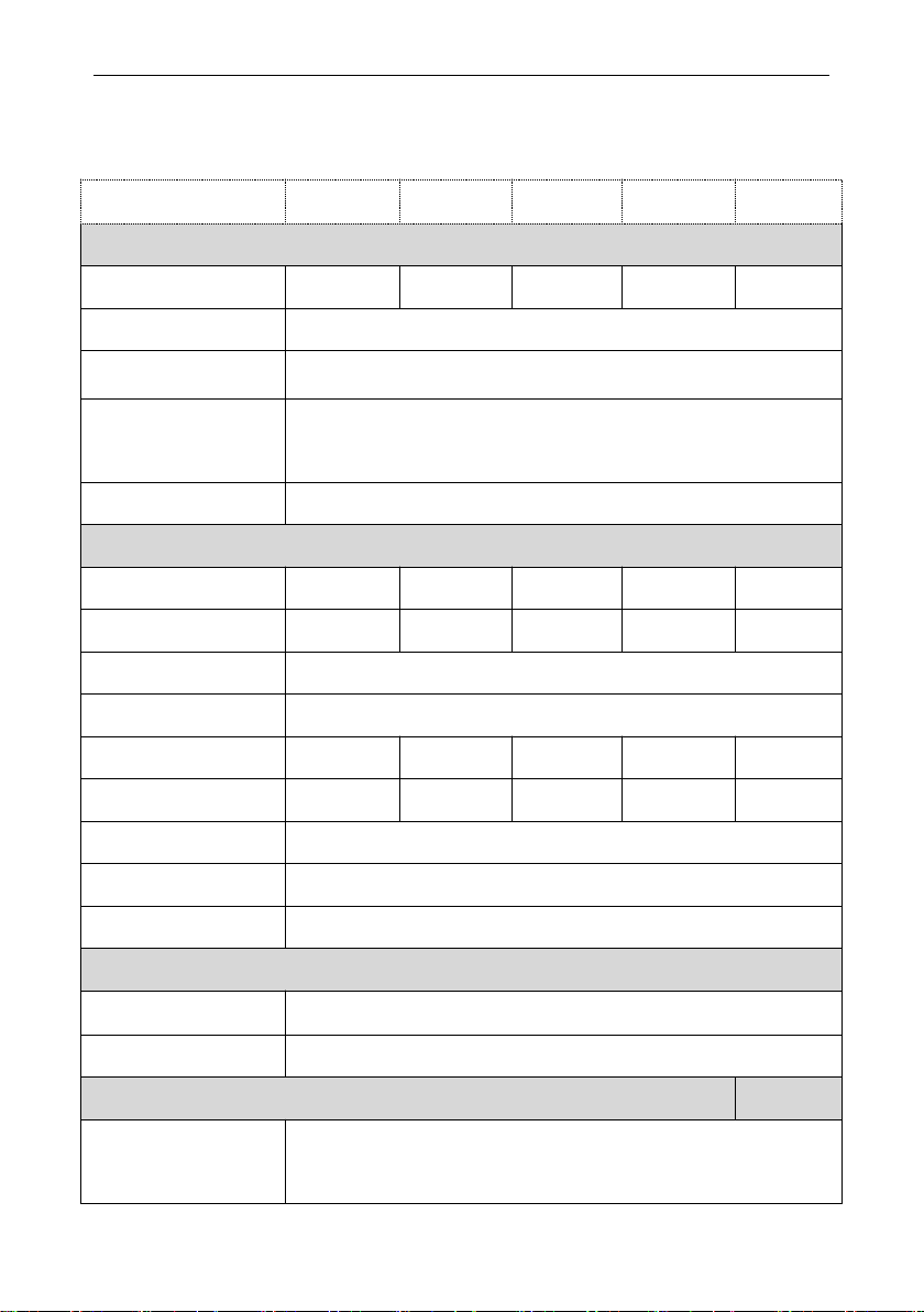
9 Technical Data
Model
SI -3.6K-S2
SI-4K-S2
SI-4.6K-S2
SI -5K-S2
SI-6K-S2
Input Data
Max. DC input power
4700W
5500W
6000W
6500W
7800W
Max. DC input voltage
550V
Operation voltage range
80V-540V
Number of independent
MPPT/strings per MPPT
2/1+1
MPPT max. current
13A/13A
AC Output Data
Rated output power
3.6KW
4KW
4.6KW
5KW
6KW
Max. output power
4000W
4400W
5000W
5500W
6600W
Rated output voltage
230V ±20%
Rated output frequency
50 /60 Hz± 5 Hz
Rated output current
15.7A
18A
20A
21.8A
26.1A
Max. output current
17.3A
20A
22A
24A
29A
Power factor
+-0.8
THDi
<3%
Grid system pattern
L+N+PE
Efficiency
Max. efficiency
97.6%
Europe efficiency
96.8%
General Data
Dimensions(W/L/H)in
mm
330/312/170
User Manual
- 19 -
10 Manufacturer Warranty
Please refer to the warranty card
11 Contact
If you have technical problems concerning our products, contact your installer or
manufacturer. During inquiring, please provide below information:
1. Inverter type
2. Modules information
3. Communication method
4. Serial number of Inverters
5. Error code of Inverters
6. Display of inverter LCD
Weight
<10kg
Operation temperature
range
–25 °C ... +60 °C
Noise
≤25dB
Heat dissipation mode
Natural
IP Class
IP65
Features
LCD display
yes
Communication
interface
WiFi/GPRS/RS485
This manual suits for next models
4
Table of contents
Other INHENERGY Inverter manuals


