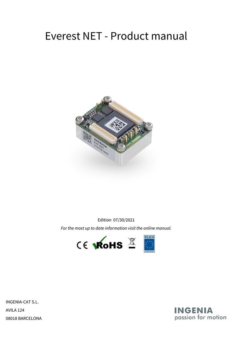
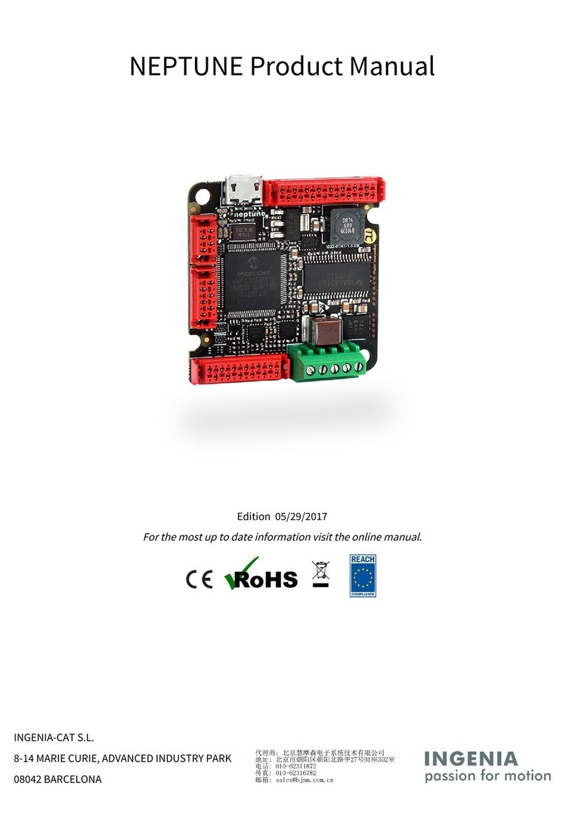
INGENIA Everest CORE User manual

INGENIA-CAT S.L.
AVILA 124
08018 BARCELONA
Everest CORE - Product Manual
Edition 08/01/2019
For the most up to date information visit the online manual.

1. Table of Contents
1. Table of Contents 2
2. General Information 4
2.1. Manual revision history ....................................................................................................................................... 4
2.2. Disclaimers and limitations of liability ............................................................................................................... 4
2.3. Contact ................................................................................................................................................................. 4
3. Safety Information 5
3.1. About this manual................................................................................................................................................ 5
3.2. Warnings............................................................................................................................................................... 5
3.3. Precautions .......................................................................................................................................................... 5
4. Product Description 6
4.1. Part numbering .................................................................................................................................................... 6
4.2. Specifications....................................................................................................................................................... 7
4.3. Thermal specifications ...................................................................................................................................... 10
5. Pinout 12
5.1. Connectors Overview......................................................................................................................................... 12
5.2. P1 and P2 Power pins ........................................................................................................................................ 12
5.3. P3 Feedback connector ..................................................................................................................................... 13
5.4. P4 Everest CORE Interface connector............................................................................................................... 16
6. Dimensions 21
7. Application Guide 22
7.1. Scope and Architecture ..................................................................................................................................... 22
7.1.1. Parts of an Everest CORE integration solution................................................................................................. 22
7.1.2. Single-Axis or Multi-Axis approach.................................................................................................................... 22
7.2. Schematic Design............................................................................................................................................... 22
7.2.1. Input Supplies .................................................................................................................................................... 23
DC Power Supply................................................................................................................................................ 23
DC Bus input stage............................................................................................................................................. 24
Logic supply ....................................................................................................................................................... 27
7.2.2. Protective circuits .............................................................................................................................................. 30
Inverse Polarity Protection................................................................................................................................ 30
Shunt Braking Resistor Transistor .................................................................................................................... 31
Safe Torque Off (STO) ........................................................................................................................................ 33
7.2.3. Inputs and Outputs ............................................................................................................................................ 35
Digital Inputs ...................................................................................................................................................... 35
Digital Outputs ................................................................................................................................................... 37
Mechanical Brake Output .................................................................................................................................. 38
7.2.4. Output Supplies ................................................................................................................................................. 40
3.3 V and 5 V Output Supplies............................................................................................................................ 40

7.2.5. Communications................................................................................................................................................ 42
Motion Control Bus ............................................................................................................................................ 42
Digital Halls ........................................................................................................................................................ 43
Quadrature / Incremental Encoder................................................................................................................... 45
Absolute Encoder............................................................................................................................................... 47
7.2.6. LED Signalling .................................................................................................................................................... 49
Schematic........................................................................................................................................................... 50
Signals description............................................................................................................................................. 50
Design Notes....................................................................................................................................................... 50
Bill of materials .................................................................................................................................................. 50
7.3. Layout Design..................................................................................................................................................... 50
7.3.1. Required files...................................................................................................................................................... 51
7.3.2. The Everest CORE component .......................................................................................................................... 52
Mechanical layer 5: positioning guide .............................................................................................................. 52
Mechanical layer 15: clearances........................................................................................................................ 53
7.3.3. Layout considerations ....................................................................................................................................... 54
Proposed Layer Stack ........................................................................................................................................ 56
Proposed Design Rules ..................................................................................................................................... 57
8. Service 58

Everest CORE - Product Manual|General Information
INGENIA |08/01/2019
4
2. General Information
2.1. Manual revision history
Revision Release Date Changes PDF
v1 12 Apr 2019 Initial version Export as pdf
For the most up to date information use the onlineProduct Manual. The PDF manual is generated only after major
changes.
2.2. Disclaimers and limitations of liability
The information contained within this document contains proprietary information belonging toINGENIA-CAT S.L.
Such information is supplied solely for the purpose of assisting users of the product in its installation.
INGENIA-CAT S.L.rejects all liability for errors or omissions in the information or the product or in other
documents mentioned in this document.
The text and graphics included in this document are for the purpose of illustration and reference only. The
specifications on which they are based are subject to change without notice.
This document may contain technical or other types of inaccuracies.The information contained within this
document is subject to change without notice and should not be construed as a commitment byINGENIA-CAT S.L.
INGENIA-CAT S.L.assumes no responsibility for any errors that may appear in this document.
Some countries do not allow the limitation or exclusion of liability for accidental or consequential damages,
meaning that the limits or exclusions stated above may not be valid in some cases.
2.3. Contact
INGENIA-CAT S.L.
120-124 Ávila St.
08018 Barcelona
Spain
Telephone: +34 932 917 682
E-mail:[email protected]
Web site:www.ingeniamc.com

Everest CORE - Product Manual|Safety Information
INGENIA |08/01/2019
5
3. Safety Information
3.1. About this manual
Read carefully this chapter to raise your awareness of potential risks and hazards when working with the Everest
CORE Servo Drive.
To ensure maximum safety in operating the Everest CORE Servo Drive, it is essential to follow the procedures
included in this guide. This information is provided to protect users and their working area when using the Everest
CORE Servo Drive, as well as other hardware that may be connected to it. Please read this chapter carefully before
starting the installation process.
3.2. Warnings
The following statements should be considered to avoid serious injury to those individuals performing the
procedures and/or damage to the equipment:
•To prevent the formation of electric arcs, as well as dangers to personnel and electrical contacts, never
connect/disconnect the Everest CORE Servo Drive while the power supply is on.
• Disconnect the EverestServo Drive from all power sources before proceeding with any possible wiring
change.
•After turning off the power and disconnecting the equipment power source, wait at least 10 seconds before
touching any parts of the controller that are electrically charged or hot.
3.3. Precautions
The following statements should be considered to avoid serious injury to those individuals performing the
procedures and/or damage to the equipment:
• The EverestServo CORE Drive components temperature may exceed 100 ºC during operation.
• Some components become electrically charged during and after operation.
•The power supply connected to this controller should comply with the parameters specified in this
document.
• When connecting the EverestServo CORE Drive to an approvedpower source, do so through a line that is
separate from any possible dangerous voltages, using the necessary insulation in accordance with safety
standards.
•High-performance motion control equipment can move rapidly with very high forces. Unexpected motion
may occur especially during product commissioning. Keep clear of any operational machinery and never
touch them while they are working.
•Do not make any connections to any internal circuitry. Only connections to designated connectors are
allowed.
•All service and maintenance must be performed by qualified personnel.
• Before turning on the EverestServo CORE Drive, check that all safety precautions have been followed, as
well as the installation procedures.

Everest CORE - Product Manual|Product Description
INGENIA |08/01/2019
6
4. Product Description
Everest CORE is a high power, highly-integrated, digital servo drive intended to be plugged or soldered to an
application-specific daughter board. The drive features best-in-class energy efficiency thanks to its state of the art
power stage, and can be easily configured with Ingenia's free-to-download softwareMotionLab 3.
Everest CORE can be interfaced by means of its proprietary Motion Control Bus protocol.
Main features:
•Ultra-small footprint
•80 VDC, 30 ARMS continuous
•Up to 99% efficiency
•Up to 75 kHz current loop, 25 kHz servo loops
•10 kHz ~ 100 kHz PWM frequency
• 16 bit ADC withVGA for current sensing
•Supports Halls, Quadrature encoder, SSI and BiSS-C
•Up to 4 simultaneous feedback sources
•Full voltage, current and temperature protections
Typical applications:
•Collaborative robot joints
•Robotic exoskeletons
•Wearable robots
•AGVs
• UAVs
•Industrial highly integrated servomotors
•Smart motors
•Battery-powered and e-Mobility
•Low inductance motors
4.1. Part numbering
Product Ordering part
number
Status Image
Everest CORE
Pluggable servo drive with
communication through proprietary
Motion Control Bus protocol.
EVE-CORE
For applications requiring a pluggable drive enabled with EtherCAT or CANopen, please see Everest NET.
For applications requiring a ready-to-go product, also enabled enabled with EtherCAT or CANopen, please
seeEverest XCR.
PRE-PROD.

Everest CORE - Product Manual|Product Description
INGENIA |08/01/2019
7
4.2. Specifications
Part number →EVE-CORE
Electrical and power specifications
Minimum DC bus supply voltage 8 VDC
Maximum DC bus supply voltage 80VDC(continuous)
85VDC(peak 100 ms)
Recommended power supply
voltage range
12 VDC ~ 72 VDC
This voltage range ensures a safety margin including power supply tolerances and regulation
during acceleration and braking.
Internal drive DC bus capacitance 6 µF
Logic supply voltage 4.9 VDC ~ 5.1 VDC
Nominal phase continuous
current (RMS)
30 A
Maximum phase peak current
(RMS)
60 A @ 3 sec
Active current limiting based on power stage and motor temperature.
Efficiency Up to 99% @ 20 kHz, 80 V, 30 A
Bus voltage utilisation > 97% @ 20 kHz, 80 V, voltage mode, no load
Motion control specifications
Standby logic supply
consumption
≤1 W
Measured with commutation turned OFF.
Supported motor types •Rotary brushless (SVPWM and Trapezoidal)
•Rotary brushed (DC)
Power stage PWM frequency
(configurable)
10 kHz, 20 kHz (default), 50 kHz & 100 kHz
Current sensing 16 bit ADC resolution. Accuracy is ±2% full scale.
Current sense resolution
(configurable)
Current gain is configurable in 4 ranges:
•2.475 mA/count
•1.352 mA/count
•0.570 mA/count
•0.379 mA/count

Everest CORE - Product Manual|Product Description
INGENIA |08/01/2019
8
Current sense ranges
(configurable)
Current ranges for the 4 configurable current gains:
•±81.1 A
•±44.3 A
•±18.7 A
•±12.4 A
Max. Current loop frequency 75 kHz
Max. servo loops frequency
(position & velocity)
25 kHz @ 75 kHz current loop
Feedbacks •Digital Halls
•Quadrature / Incremental encoder
•Absolute Encoder: up to 2 at the same time, combining any of the
following:
•BiSS-C (up to 2 in daisy chain topology)
•SSI
*Only a specific subset of absolute encoders are supported. Contact Ingenia for further
information.
Supported target sources Network communication (Motion Control Bus)
Control modes •Cyclic Synchronous Position
•Cyclic Synchronous Velocity
•Cyclic Synchronous Current
•Profile Position (trapezoidal & s-curves)
•Profile Velocity
•Interpolated Position (P, PT, PVT)
•Homing
Inputs/outputs and protections
General purpose Inputs and
outputs
4 x non-isolated single-ended digital inputs - 3.3 V logic level. Can be
configured as:
•General purpose
•Positive or negative homing switch
•Positive or negative limit switch
•Quick stop input
4 xnon-isolated single-endeddigital outputs - 3.3 V logic level, 3 mA max.
sink / source current. Can be configured as:
•General purpose
•Operation enabled event flag
•External shunt braking resistor driving signal
1 x ±3.3 V ,16-bit, differential analog input for load cells or torque sensors.
Can be read by the Master to close a torque loop.
Shunt braking resistor output Configurable over any of the digital outputs (see above).
Enabling this function would require an external transistor or power driver.

Everest CORE - Product Manual|Product Description
INGENIA |08/01/2019
9
Motor brake output Dedicated, PWM capable, 3.3 V digital output for driving a mechanical
brake. Turn-on and turn-off times are configurable.
Enabling this function would require an external transistor or power driver.
Safe Torque OFF inputs 2 x dedicated, non-isolated STO digital inputs (3.3 V and 5 V tolerant).
Motor temperature input 1 x dedicated, 5 V, 12-bit, single-ended analog input for measuring motor
temperature.
Protections •Hardcoded / hardwired Drive protections:
•Automatic current derating on voltage, current and
temperature
•Short-circuit Phase to DC bus
•Short-circuit Phase to Phase
•Short-circuit Phase to GND
•Configurable protections:
•DC bus over-voltage
•DC bus under-voltage
•Drive over-temperature
•Drive under-temperature
•Motor over-temperature (requires external sensor)
•Current overload (I2t). Configurable up to Drive limits
•Voltage mode over-current (with a closed current loop,
protection effectiveness depends on the PID).
•Motion Control protections:
•Halls sequence / combination error (Pending
implementation)
•Limit switches
•Position following error
•Velocity / Position out of limits
Communications
MCB Proprietary Motion Control Bus protocol based on SPI.
Environmental conditions
Aluminium case Yes (connectors side open)
PE isolation > 300 MΩ@ 1000 V
Case temperature Operation:
•-40 ºC to +60 ºC at full current
•+60 ºC to +85 ºC with derated current
For further information, see Thermal Specifications below.
Storage:
•-40 ºC to +100 ºC
Maximum humidity 5% ~ 85% non-condensing

Everest CORE - Product Manual|Product Description
INGENIA |08/01/2019
10
Mechanical specifications
Horizontal dimensions 34.5 mm x 26 mm
Height 10.4 mm (case)
17 mm (including full length of the power pins)
Weight 16 gr
Certifications
Certifications CE, RoHS
STO SIL3 (certification pending)
4.3. Thermal specifications
Thermal performance of Everest CORE is specified as function of thetemperature measured in its aluminium
case, theDC bus voltageand thePWM commutation frequency. This 3 parameters could ultimately determine
the maximum continuous current the Everest CORE can output, provided that anactive deratingalgorithm will be
continuously protecting it from thermal over-stress. Notice that PWM commutation frequency cannot be changed
dynamically, but pre-selected to match the application needs: most probably 10 kHz will be selected for
highestcurrentat a given temperature (be aware that selecting this frequency may cause audible noise), but 100
kHz will be preferred to control a low inductance motor.
The following figure show the maximum phase current at different case temperatures and DC bus voltages.
Herecurrent is expressed in RMS.To obtain the equivalent current in amplitude just multiply it by√2.
To ensure a proper performance of Everest CORE, thecase temperature must be held always below 85 ºC (Tc-
max=85 ºC).

Everest CORE - Product Manual|Product Description
INGENIA |08/01/2019
11
Following figure show the theoreticalpower lossesat different operating points.
Take a look to theThermal Dissipationsection below to learn how to dimension a heatsink to allow Everest CORE
reaching a target current under an specific ambient temperature.

Everest CORE - Product Manual|Pinout
INGENIA |08/01/2019
12
5. Pinout
5.1. Connectors Overview
5.2. P1 and P2 Power pins
P1 Supply Power pins
Pin Name Type Function
1 POW_SUP Power Power supply positive (DC bus).
2 GND_P Power supply negative (Power Ground).
Chassis PE Protective Earth connected to driver housing and fixing M2.5 threads.

Everest CORE - Product Manual|Pinout
INGENIA |08/01/2019
13
P2 Motor Power pins
Pin Name Type Function
1 PH_A Power Motor phase A for 3-phase motors, positive for DC motors.
2 PH_B Motor phase B for 3-phase motors, negative for DC motors.
3 PH_C Motor phase C for 3-phase motors (do not connect for DC motors).
Chassis PE Protective Earth connected to driver housing and fixingM2.5 threads.
Everest CORE
connector
Recommended mating contact Description
Up to 11.2 ARMS rated motors
Ø 1.52 mm, 4 mm
pitch, gold plated
power pins.
Beryllium copper TH pin receptacle. Gold plated.
Mill-Max
9372-0-15-15-23-27-10-0
> 11.2 ARMS rated motors
Direct solder to PCB. TH pad with min. hole Ø 1.63 mm. Ensure PCB track are wide enough to
withstand the target current.
5.3. P3 Feedback connector
The pinout of the Feedback connector is exactly the same for for Everest CORE (EVE_CORE) and Everest NET
(EVE_NET) although the position of the connector is different.

Everest CORE - Product Manual|Pinout
INGENIA |08/01/2019
14
P3 Feedback connector
# Signal
name
Description Type # Signal
name
Description Type
1GND_A Analog Ground. Do not connect
to GND_D directly, use a ferrite
bead or 1 Ωresistor in
between.
Power 2GND_A Analog Ground. Do not connect
to GND_D directly, use a ferrite
bead or 1 Ωresistor in
between.
Power
3DNC Reserved. Do not connect
(leave floating).
-4AN1_P Analog input for torque
sensing.
16 bit
differe
ntial
analog
input
5DNC 6AN1_N
7DNC 8DNC Reserved. Do not connect
(leave floating).
-
9DNC 10 DNC
11 DNC 12 DNC
13 MOTO
R_TEM
P
Motor temperature sensor
input. 0 V to 5 V level high
impedance input.
12 bit
single-
ended
analog
input
14 DNC
15 GND_D Digital signal Ground. Power 16 NC Internally not connected.
Recommended to leave them
unconnected.
17 HALL_
1
Digital hall 1. Input 18 NC
19 HALL_
2
Digital hall 2. 20 GND_A Analog Ground. Do not connect
to GND_D directly, use a ferrite
bead or 1 Ωresistor in
between.
Power
21 HALL_
3
Digital hall 3. 22 GND_D Digital signal Ground.
23 CLL Reserved. Must be tied or
pulled-down to GND_D.
-24 DIG_E
NC_1A
Digital encoder 1 A. Input
25 CHL Reserved. Must be tied or
pulled-up to 3.3 V.
26 DIG_E
NC_1B
Digital encoder 1 B.

Everest CORE - Product Manual|Pinout
INGENIA |08/01/2019
15
27 CLL Reserved. Must be tied or
pulled-down to GND_D.
28 DIG_E
NC_1Z
Digital encoder 1 Index.
29 CHL Reserved. Must be tied or
pulled-up to 3.3 V.
30 DIG_E
NC_2A
Digital encoder 2 A.
31 DNC Reserved. Do not connect
(leave floating).
32 DIG_E
NC_2B
Digital encoder 2 B.
33 DNC 34 DIG_E
NC_2Z
Digital encoder 2 Index.
35 DNC 36 GND_D Digital signal Ground. Power
37 DNC 38 ABSEN
C1_CL
K
Clock output for Absolute
Encoder 1.
Output
39 DNC 40 ABSEN
C1_DA
TA
Data input for Absolute
Encoder 1 (supports SSI or up
to 2 BiSS-C encoders
connected in daisy chain
topology).
Input
41 DNC 42 DNC Reserved. Do not connect
(leave floating).
-
43 DNC 44 GND_D Digital signal Ground. Power
45 DNC 46 DNC Reserved. Do not connect
(leave floating).
-
47 DNC 48 DNC
49 DNC 50 DNC
51 DNC 52 DNC
53 DNC 54 DNC
55 DNC 56 DNC
57 DNC 58 DNC
59 GND_D Digital signal Ground. Power 60 GND_D Digital signal Ground. Power
Notes and naming conventions:
•All pins are tolerant to 3.3 V unless otherwise noted.
•"_P" and "_N" indicates positive and negative of differential signals
•"\" Indicates inverted (active low) signal

Everest CORE - Product Manual|Pinout
INGENIA |08/01/2019
16
•"NC" means Not Connected. Pins marked with NC can be tied to GND or 3.3 V,but best practice is to leave
them unconnected.
•"DNC" means Do Not Connect. Pins marked with DNC must not be tied to any driving voltage, including GND
or 3.3 V.
• "CLL" means Connect to Low Level.Pins marked with CLL must be tied or pulled-down to 0 V.
• "CHL" means Connect to High Level.Pins marked with CHL must be tied or pulled-up to 3.3 V.
Manufacturer Everest CORE
connector
Required mating
connector
Description
Hirose Electric 60-pin mezzanine stacking board
connector. 0.5 mm pitch. Center strip, gold-
plated surface mount contacts. 3 mm
stacking height.
DF12(3.0)-60DP-0.5V(86
)
DF12(3.0)-60DS-0.5V(86)
5.4. P4 Everest CORE Interface connector
Although using the samephysical connector as Everest NET (EVE-NET), position and pinout is different in Everest
CORE (EVE-CORE).
P4 Everest CORE Interface connector
# Signal
name
Description Type # Signal
name
Description Type
1GND_D Digital signal Ground. Power 2GND_D Digital signal Ground. Power

Everest CORE - Product Manual|Pinout
INGENIA |08/01/2019
17
35V_D 5 V, 300 mA continuous logic
supply input. Must be low
ripple and ensure ±2%
regulation tolerance or less. It
is advised to connect all four
5V_D pins. It is recommended
to provide at least 500 mA
input current if pins 9 or 10
(3.3V_D) are used to drive
external circuits.
Power
input
45V_D 5 V, 300 mA continuous logic
supply input. Must be low
ripple and ensure ±2%
regulation tolerance or less. It
is recommended to connect all
four 5V_D pins. It is advised to
provide at least 500 mA input
current if pins 9 or 10 (3.3V_D)
are used to drive external
circuits.
Power
input
55V_D 65V_D
7GND_D Digital signal Ground. Power 8GND_D Digital signal Ground. Power
93.3V_D 3.3 V, 250 mA max. output to
supply peripherals. An
excessive current demand on
this pin could cause failure or
even permanent damage to the
Everest CORE.
Power
output
10 3.3V_D 3.3 V, 250 mA max. output to
supply peripherals. An
excessive current demand on
this pin could cause failure or
even permanent damage to the
Everest CORE.
Power
output
11 GND_D Digital signal Ground. Power 12 GND_D Digital signal Ground. Power
13 GND_D 14 MCB_S
PI_MIS
O
Motion Control Bus, Master
input Slave output
Output
15 GND_D 16 MCB_S
PI_MO
SI
Motion Control Bus, Master
output Slave input
Input
17 GND_D 18 \MCB_
SPI_CS
Motion Control Bus, Chip
Select output
19 GND_D 20 MCB_S
PI_CLK
Motion Control Bus, Clock
output
21 GND_D 22 MCB_S
YNC0
Motion Control Bus,
synchronization signal 0
23 GND_D 24 MCB_S
YNC1
Motion Control Bus,
synchronization signal 1
Output
25 GND_D 26 MCB_I
RQ
Motion Control Bus, interrupt
request output
27 GND_D 28 DNC Reserved. Do not connect
(leave floating).
-
29 NC Internally not connected.
Recommended to leave them
unconnected.
-30 GND_D Digital signal Ground. Power
31 NC 32 GND_D

Everest CORE - Product Manual|Pinout
INGENIA |08/01/2019
18
33 \STO1 Safe Torque Off input 1 (non-
isolated). Both \STO1 and
\STO2 must be high-level (3.3 V
and 5 V level compatible) to
allow operation of the motor.
Holding different logic states
(STO1 ≠STO2) for more than 1s
will cause a latching fault.
Input 34 \STO2 Safe Torque Off input 2 (non-
isolated). Both \STO1 and
\STO2 must be high-level (3.3 V
and 5 V level compatible) to
allow operation of the motor.
Holding different logic states
(STO1 ≠STO2) for more than 1s
will cause a latching fault.
Input
35 DNC Reserved. Do not connect
(leave floating).
-36 DNC Reserved. Do not connect
(leave floating).
-
37 FAULT
_SIGNA
L
Fault state signalling output.
Can directly drive a (typically)
red LED anode at 3.3 V up to 3
mA.
Output 38 \HW_R
ESET
Everest CORE reset input.
Keeps the motion controller
disabled with low power
consumption. 2 kΩpull-up to
3.3 V is internally included.
Input
39 GND_D Digital signal Ground. Power 40 DNC Reserved. Do not connect
(leave floating).
-
41 \EXT_F
AULT
External fault input. Could be
configured to force the Everest
CORE state-machine to the
Fault state (motor will be
stopped) when the pin is driven
to 0 V. Includes an internal
weak pull-up, although
external pull-up to 3.3 V is
advised.
Input 42 PWM_
BRAKE
PWM output for driving a
mechanical brake.
Configurable up to 20 kHz. High
level indicates the motor is free
to move.
Output
43 GPO4 Digital Output 4. Output 44 DNC Reserved. Do not connect
(leave floating).
-
45 DNC Reserved. Do not connect
(leave floating).
-46 DNC
47 GPI1 Digital Input 1. Input 48 DNC
49 GPI2 Digital Input 2. 50 ABSEN
C2_CL
K
Clock output for Absolute
Encoder 2.
Output
51 ABSEN
C2_DA
TA
Data input for Absolute
Encoder 2 (supports SSI only)
52 DNC Reserved. Do not connect
(leave floating).
-
53 GPI3 Digital Input 3. 54 DNC
55 GPO1 Digital Output 1. Output 56 GPO2 Digital Output 2. Output
57 GPO3 Digital Output 3. 58 GPI4 Digital Input 4. Input
59 GND_D Digital signal Ground. Power 60 GND_D Digital signal Ground. Power
61 DNC Reserved. Do not connect
(leave floating).
-62 DNC Reserved. Do not connect
(leave floating).
-
63 DNC 64 DNC

Everest CORE - Product Manual|Pinout
INGENIA |08/01/2019
19
65 DNC 66 DNC
67 GND_D Digital signal Ground. Power 68 GND_D Digital signal Ground. Power
69 NC Internally not connected.
Recommended to leave them
unconnected.
-70 NC Internally not connected.
Recommended to leave them
unconnected.
-
71 NC 72 NC
73 NC 74 NC
75 1.65V_
REF
1.65 V voltage reference output
with sink/source capability up
to ±10 mA. An excessive current
demand or noise coupled to
this pin can cause a loss of
performance or even
malfunction of Everest CORE:
route by following the best
layout practices.
Power
output
76 NC
77 3.3V_R
EF
3.3 V voltage reference output
with sink/source capability up
to ±10 mA. An excessive current
demand or noise coupled to
this pin can cause a loss of
performance or even
malfunction of Everest CORE:
route by following the best
layout practices.
78 DNC Reserved. Do not connect
(leave floating).
79 GND_A Analog Ground. Do not connect
to GND_D directly, use a ferrite
bead or 1 Ωresistor in
between.
Power 80 GND_A Analog Ground. Do not connect
to GND_D directly, use a ferrite
bead or 1 Ωresistor in
between.
Power
Notes and naming conventions:
•All pins are tolerant to 3.3 V unless otherwise noted.
•"_P" and "_N" indicates positive and negative of differential signals
•"\" Indicates inverted (active low) signal
•"NC" means Not Connected. Pins marked with NC can be tied to GND or 3.3 V, but best practice is to leave
them unconnected.
•"DNC" means Do Not Connect. Pins marked with DNC must not be tied to any driving voltage, including GND
or 3.3 V.
Motion Control Bus
Everest CORE can be controlled as a slave by means of its proprietary Motion Control Bus (MCB). Check
how in the Summit Series Reference Manual.

Everest CORE - Product Manual|Pinout
INGENIA |08/01/2019
20
Manufacturer Everest CORE
connector
Required mating
connector
Description
Hirose Electric 80-pin mezzanine stacking board
connector. 0.5 mm pitch. Center strip, gold-
plated surface mount contacts. 3 mm
stacking height.
DF12(3.0)-80DP-0.5V(86
)
DF12(3.0)-80DS-0.5V(86)
Other manuals for Everest CORE
1
Table of contents
Other INGENIA Computer Hardware manuals
Popular Computer Hardware manuals by other brands

ADLINK Technology
ADLINK Technology GEME-4000 Series user manual

Pico Macom
Pico Macom MOR-CS Installation and operation manual

IOtech
IOtech DaqBoard/3000 Series user manual

Whadda
Whadda RFM69HCW user manual

Supermicro
Supermicro AOM-C25G-i2SM-12 user guide

Cypress Semiconductor
Cypress Semiconductor CY8CKIT-042-BLE user guide