manuals.online logo
Brands
  1. Home
  2. •
  3. Brands
  4. •
  5. Ingersoll-Rand
  6. •
  7. Water Pump
  8. •
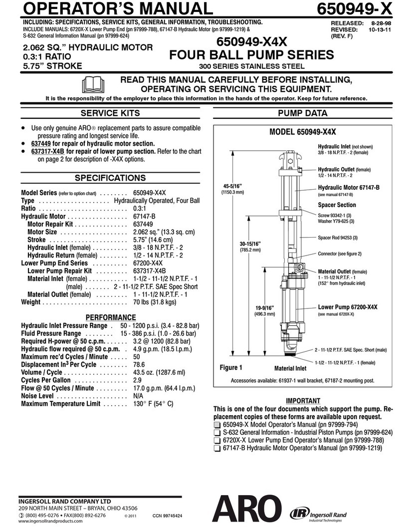
  9. Ingersoll-Rand ARO NM2202A 1 31 Series User manual

Ingersoll-Rand ARO NM2202A 1 31 Series User manual

This manual suits for next models

17

Other Ingersoll-Rand Water Pump manuals

Ingersoll-Rand ARO 666300 C Series User manual

Ingersoll-Rand

Ingersoll-Rand ARO 666300 C Series User manual

Ingersoll-Rand AF060BL Series User manual

Ingersoll-Rand

Ingersoll-Rand AF060BL Series User manual

Ingersoll-Rand 650715-C User manual

Ingersoll-Rand

Ingersoll-Rand 650715-C User manual

Ingersoll-Rand ARO 66615 Series User manual

Ingersoll-Rand

Ingersoll-Rand ARO 66615 Series User manual

Ingersoll-Rand ARO 66625 Series User manual

Ingersoll-Rand

Ingersoll-Rand ARO 66625 Series User manual

Ingersoll-Rand ARO EVO EP20 Series User manual

Ingersoll-Rand

Ingersoll-Rand ARO EVO EP20 Series User manual

Ingersoll-Rand ARO 650432-X43-C Series User manual

Ingersoll-Rand

Ingersoll-Rand ARO 650432-X43-C Series User manual

Ingersoll-Rand ARO 66266 Series User manual

Ingersoll-Rand

Ingersoll-Rand ARO 66266 Series User manual

Ingersoll-Rand ARO AF0409A13 Series User manual

Ingersoll-Rand

Ingersoll-Rand ARO AF0409A13 Series User manual

Ingersoll-Rand ARO 650717-C User manual

Ingersoll-Rand

Ingersoll-Rand ARO 650717-C User manual

Ingersoll-Rand PD05P Series User manual

Ingersoll-Rand

Ingersoll-Rand PD05P Series User manual

Ingersoll-Rand LM2203A-XX-B Series User manual

Ingersoll-Rand

Ingersoll-Rand LM2203A-XX-B Series User manual

Ingersoll-Rand ARO LM2350E-B Series User manual

Ingersoll-Rand

Ingersoll-Rand ARO LM2350E-B Series User manual

Ingersoll-Rand ARO PD20 Series User manual

Ingersoll-Rand

Ingersoll-Rand ARO PD20 Series User manual

Ingersoll-Rand MP PUMPS CHEMFLO 2 User manual

Ingersoll-Rand

Ingersoll-Rand MP PUMPS CHEMFLO 2 User manual

Ingersoll-Rand MP PUMPS CHEMFLO 4 56C User manual

Ingersoll-Rand

Ingersoll-Rand MP PUMPS CHEMFLO 4 56C User manual

Ingersoll-Rand 66266-XXX-B User manual

Ingersoll-Rand

Ingersoll-Rand 66266-XXX-B User manual

Ingersoll-Rand 650883-XXX-B User manual

Ingersoll-Rand

Ingersoll-Rand 650883-XXX-B User manual

Ingersoll-Rand ARO 670036-15X User manual

Ingersoll-Rand

Ingersoll-Rand ARO 670036-15X User manual

Ingersoll-Rand ARO 670154-A User manual

Ingersoll-Rand

Ingersoll-Rand ARO 670154-A User manual

Ingersoll-Rand PD30X-X User manual

Ingersoll-Rand

Ingersoll-Rand PD30X-X User manual

Ingersoll-Rand PM10X-X-X-A02 User manual

Ingersoll-Rand

Ingersoll-Rand PM10X-X-X-A02 User manual

Ingersoll-Rand Easy lub 86603313 User manual

Ingersoll-Rand

Ingersoll-Rand Easy lub 86603313 User manual

Ingersoll-Rand ARO PD10 Series User manual

Ingersoll-Rand

Ingersoll-Rand ARO PD10 Series User manual

Popular Water Pump manuals by other brands

Watershed Innovations HYDRAPUMP SMART FLEX Instructional manual

Watershed Innovations

Watershed Innovations HYDRAPUMP SMART FLEX Instructional manual

Graco Modu-Flo AL-5M instructions

Graco

Graco Modu-Flo AL-5M instructions

Messner MultiSystem MPF 3000 operating instructions

Messner

Messner MultiSystem MPF 3000 operating instructions

Xylem Bell & Gossett WEHT0311M Installation, operation and maintenance instructions

Xylem

Xylem Bell & Gossett WEHT0311M Installation, operation and maintenance instructions

WilTec 50739 Operation manual

WilTec

WilTec 50739 Operation manual

Franklin Electric Little Giant 555702 HRK-360S instruction sheet

Franklin Electric

Franklin Electric Little Giant 555702 HRK-360S instruction sheet

VS ZJ Series Operating	 instruction

VS

VS ZJ Series Operating instruction

Flotec FPZS50RP owner's manual

Flotec

Flotec FPZS50RP owner's manual

SKF Lincoln FlowMaster II User and maintenance instructions

SKF

SKF Lincoln FlowMaster II User and maintenance instructions

Xylem Lowara LSB Series Installation, operation and maintenance instructions

Xylem

Xylem Lowara LSB Series Installation, operation and maintenance instructions

Water Duro Pumps DCJ500 Operating & installation instructions

Water

Water Duro Pumps DCJ500 Operating & installation instructions

Action P490 Operating instructions & parts manual

Action

Action P490 Operating instructions & parts manual

Flo King Permacore Reusable Carbon Bag Disassembly. & Cleaning Instructions

Flo King

Flo King Permacore Reusable Carbon Bag Disassembly. & Cleaning Instructions

ARO ARO PD15P-X Operator's manual

ARO

ARO ARO PD15P-X Operator's manual

Pumptec 112V Series Operating instructions and parts manual

Pumptec

Pumptec 112V Series Operating instructions and parts manual

Virax 262070 user manual

Virax

Virax 262070 user manual

Neptun NPHW 5500 operating instructions

Neptun

Neptun NPHW 5500 operating instructions

Sensidyne Gilian BDX-II Operation & service manual

Sensidyne

Sensidyne Gilian BDX-II Operation & service manual

manuals.online logo
manuals.online logoBrands
  • About & Mission
  • Contact us
  • Privacy Policy
  • Terms and Conditions

Copyright 2025 Manuals.Online. All Rights Reserved.

CCN 20076626
OPERATOR’S MANUAL NM2202A-X
RELEASED: 3-7-03
REVISED: 6-1-10
(REV. D)
TWO-BALL PUMP SERIES
2” AIR MOTOR
2:1 RATIO
3” STROKE
INCLUDE MANUALS: 67319-X LOWER PUMP END (PN 97999-1044), 67316 AIR MOTOR (PN 97999-1045)
& S-632 GENERAL INFORMATION MANUAL (PN 97999-624).
SPECIFICATIONS, SERVICE KITS, GENERAL INFORMATION, TROUBLESHOOTING
NM2202A-X1-X31
CARBON STEEL
READ THIS MANUAL CAREFULLY BEFORE INSTALLING,
OPERATING OR SERVICING THIS EQUIPMENT.
It is the responsibility of the employer to place this information in the hands of the operator. Keep for future reference.
SERVICE KITS
•Use only genuine ARORreplacement parts to assure compatible
pressure rating and longest service life.
•637377 for repair of air motor section.
•637378-X31 for repair of 67319-X31 and 67320-X31 lower pump
ends.
SPECIFICATIONS
Model Series (refer to option chart) NM2202A-X1-X31........
Type Air Operated, Two-ball.........................
Ratio 2:1.........................
Air Motor 67316......................
Motor Repair Kit 637377...............
Motor Diameter 2” (5.08 cm)................
Stroke (Double Acting) 3” (7.62 cm)..........
Air Inlet (female) 1/4 - 18 N.P.T.F. - 1...............
Lower Pump End Series
NM2202A-11-731 67320-731.............
NM2202A-11-B31 67320-B31.............
NM2202A-11-C31 67320-C31.............
NM2202A-11-J31 67320-J31..............
NM2202A-41-731 67319-731.............
NM2202A-41-B31 67319-B31.............
NM2202A-41-C31 67319-C31.............
NM2202A-41-J31 67319-J31.............
Lower Pump Repair Kit 637378-X31..........
Material Inlet
NM2202A-11-X31 (female) 1-1/2 - 11-1/2 N.P.T.F........
NM2202A-41-X31 immersed.............
Material Outlet (female) 3/4 - 14 N.P.T.F...........
Weight See chart........................
PERFORMANCE
Air Inlet Pressure Range 0 - 150 p.s.i. (0 - 10.3 bar)..........
Fluid Pressure Range 0 - 351 p.s.i. (0 - 24.2 bar)............
Maximum Rec’d Cycles / Minute 120....
Displacement In.3Per Cycle 8.28........
Volume / Cycle 4.59 oz. (135.6 ml)..................
Cycles Per Gallon 27.9...............
Flow @ 60 Cycles / Minute 2.15 g.p.m. (8.14 l.p.m.).........
Noise Level @ 100 p.s.i. 80 db(A) *...........
Accessories Available 61113 Wall Mount Bracket............
66073-1 Air Line Connection Kit
*The pump sound pressure level has been updated to an Equivalent Continuous Sound
Level (LAeq) to meet the intent of ANSI S1. 13-1971, CAGI-PNEUROP S5.1 using four
microphone locations.
PUMP DATA
67316 Air Motor
(see manual 67316)
Figure 1
Material Outlet (female)
3/4 - 14 N.P.T.F.
Lower Pump 673XX-X
(see manual 67319-X)
Air Inlet (female)
1/4 - 18 N.P.T.F. - 1
NOTE: Dimensions are shown in inches and (mm), supplied for reference only and are
typically rounded up to the nearest 1/16 inch.
MODEL NM2202A-X1-X31
11/16” (17.5 mm)
Spacer Section
Material Inlet (female)
1-1/2 - 11-1/2 N.P.T.F.
“B”
“A”
Model Number “A” (mm) “B” (mm) Weight (kg)
NM2202A-11-X31 34-3/16” (868.0 mm) 20-1/16” (508.8 mm) 17.5 lbs (7.9)
NM2202A-41-X31 47-7/8” (1214.8 mm) 33-11/16” (855.6 mm) 19.6 lbs (8.9)
67145-4-B Bung Assembly
2-11-1/2N.P.T.
96073 Spring
Y99-47-C Cap Screw (4)
Tighten to 50 in. lbs (5.6 Nm)
96068 Plate
IMPORTANT
This is one of the four documents which support the pump. Re-
placement copies of these forms are available upon request.
=NM2202A-X MODEL OPERATOR’S MANUAL
-GENERAL INFORMATION -- INDUSTRIAL PISTON PUMPS
-67319-X LOWER PUMP END OPERATOR’S MANUAL
-67316 AIR MOTOR OPERATOR’S MANUAL
INGERSOLL RAND COMPANY LTD
209 NORTH MAIN STREET – BRYAN, OHIO 43506
(800) 495-0276 FAX(800) 892-6276 © 2010
www.ingersollrandproducts.com
PN 97999-1028
NM2202A-XPage2of2
PUMP OPTION DESCRIPTION CHART
NM2202A - X 1 - X 3 1
CONTAINER SUITABILITY
PLUNGER TYPE
SPRING ARRANGEMENT
CONTAINER SUITABILITY PACKING MATERIAL
1 - Universal (Stub) 7 - PTFE (upper and lower)
4 - 55 Gallon B - UHMW-PE (upper) / PTFE (lower)
C - UHMW-PE (upper and lower)
J - Polyurethane (upper) / UHMW-PE (lower)
SPRING ARRANGEMENT PLUNGER TYPE
3 - No Spring 1 - Standard (Carbon steel)
PACKING MATERIAL
GENERAL DESCRIPTION
Model NM2202A-X Series two-ball, double acting pumps are intended
to be used primarily for oil transfer and delivery systems. It is best to use
this pump with low -- medium viscosity fluids. It uses carbon steel and
other materials which make it compatible with most petroleum based lu-
brication products. The two-ball design provides better priming of the
lower foot valve. Double acting pumps will deliver material on both the up
and down stroke.
NOTE: If this pump was purchased separately (not part of a system),
consult your sales representative for compatible dispensing accesso-
ries which will best match the application. All accessories must be able
to withstand the maximum pressure developed by the pump.
WARNING HAZARDOUS PRESSURE. Do not exceed maxi-
mum operating pressure of 351 p.s.i. (24.2bar) at 150 p.s.i. (10.3
bar) inlet air pressure.
PUMP RATIO X MAXIMUM PUMP
INLET PRESSURE TO PUMP MOTOR =FLUID PRESSURE
Pump ratio is an expression of the relationship between the pump motor area and the
lower pump end area. EXAMPLE: When 150 p.s.i. (10.3 bar) inlet pressure is supplied
to the motor of a 4:1 ratio pump it will develop a maximum of 600 p.s.i. (41.4 bar) fluid
pressure (at no flow) - as the fluid control is opened, the flow rate will increase as the
motor cycle rate increases to keep up with the demand.
WARNING Refer to general information sheet for additional
safety precautions and important information.
NOTICE: Thermal expansion can occur when the fluid in the materi-
al lines is exposed to elevated temperatures. Example: Material
lines located in a non-insulated roof area can warm due to sunlight.
Install a pressure relief valve in the pumping system.
Replacement warning label (pn 94520) is available upon request.
TROUBLE SHOOTING
Pump problems can occur in either the Air Motor Section or the Lower
Pump End Section. Use these basic guidelines to help determine which
section is affected. Be sure to eliminate any possible non-pump prob-
lems before suspecting pump malfunction.
Pump will not cycle.
•No pressure to the motor. See motor manual.
•Damaged motor. Service motor
No material at the outlet (pump continually cycles).
•Check the material supply, disconnect or shut off the air supply and
replenish the material, reconnect.
Material on one stroke only (fast downstroke).
•The lower check may not be seating in the foot valve (see lower
pump disassembly). Remove the check from the foot valve, clean
and inspect the valve seat area. If check or foot valve are damaged,
replace.
Material on one stroke only (fast upstroke).
•The middle packings may be worn (see lower pump disassembly).
Replace the seals as necessary.
PUMP CONNECTION - UPPER / LOWER
NOTE: All threads are right hand.
1. Lay the pump assembly on a workbench.
2. Remove four (Y99-47-C) cap screws and pull the air motor from the
lower pump end until the motor piston rod is in the “down” position
and the lower pump end rod is in the “up” position.
3. Remove the (Y15-31-C) cotter pin and (96064) pin, releasing the air
motor from the lower pump end.
Lower Pump Rod
Pump Motor Piston Rod
Cotter Pin Y15-31-C
PUMP CONNECTOR DETAIL
Figure 2
Pin 96064
REASSEMBLY
1. Assemble motor piston rod to the lower pump end rod, aligning thru
holes.
2. Assemble (96064) pin through hole, securing rods.
3. Assemble (Y15-31-C) cotter pin through hole in pin.
4. Align tie rods with holes in (96068) plate and pump outlet body.
5. Assemble four (Y99-47-C) cap screws, securing air motor. NOTE:
Tighten cap screws to 50 in. lbs (5.65 Nm).