manuals.online logo
Brands
  1. Home
  2. •
  3. Brands
  4. •
  5. Ingersoll-Rand
  6. •
  7. Water Pump
  8. •
  9. Ingersoll-Rand LM2203A Series User manual

Ingersoll-Rand LM2203A Series User manual

OPERATOR’S MANUAL LM2203A-X-C4
TWO-BALL PUMP SERIES
2” AIR MOTOR
3:1 RATIO
0 - 450 P.S.I. RANGE
INCLUDE MANUAL: S-632 GENERAL INFORMATION (PN 97999-624)
INCLUDING: SPECIFICATIONS, SERVICE KITS, GENERAL INFORMATION, PARTS, TROUBLESHOOTING
LM2203A-XX-C4
READ THIS MANUAL CAREFULLY BEFORE INSTALLING,
OPERATING OR SERVICING THIS EQUIPMENT.
It is the responsibility of the employer to place this information in the hands of the operator. Keep for future reference.
SERVICE KITS
•Use only genuine ARORreplacement parts to assure compatible
pressure rating and longest service life.
•637481 Pump Rebuild Kit. Includes the necessary soft parts for
normal service of the entire pump.
SPECIFICATIONS
Model Series (refer to option chart) LM2203A-XX-C4........
Type Air Operated, Two Ball,.........................
Double Acting Oil Pump
Ratio 3:1.........................
Air Motor Diameter 2’’ (5.08 cm)..............
Stroke 3’’ (7.62 cm)......................
Air Inlet (female)
LM2203A-X1-C4 1/4 - 18 N.P.T.F..............
LM2203A-X2-C4 Rp 1/4 (1/4 - 19 BSP Parallel)..........
Material Inlet (female)
LM2203A-X1-C4 3/4 - 14 N.P.T..............
LM2203A-X2-C4 Rp 3/4 (3/4 - 14 BSP Parallel)..........
Material Outlet (female)
LM2203A-X1-C4 1/2 - 14 N.P.T.F. - 1.............
LM2203A-X2-C4 Rp 1/2 (1/2 - 14 BSP Parallel)..........
Pump Construction Carbon Steel............
Dimensional Data See chart...............
Weight See chart........................
PERFORMANCE
Air Inlet Pressure Range 0 - 150 p.s.i. (0 - 10.3 bar)..........
Fluid Pressure Range 0 - 450 p.s.i. (0 - 31.0 bar)............
Maximum Rec’d Cycles / Minute 125....
Displacement In3Per Cycle 6.2........
Volume / Cycle 3.46 oz. (102.28 ml)..................
Cycles Per Gallon (Liter) 37 (9.8)..........
Maximum Working Flow Rate 6 g.p.m. (23 l.p.m.)......
Maximum Flow Rate 9 g.p.m. (34 l.p.m.).............
Noise Level @ 100 p.s.i. - 124 c.p.m. 80 db(A)*.
Accessories Available 61113 Wall Mount Bracket............
66073-1 Air Line Connection Kit
*The pump sound pressure level has been updated to an Equivalent Continuous Sound
Level (LAeq) to meet the intent of ANSI S1. 13-1971, CAGI-PNEUROP S5.1 using four
microphone locations.
PUMP DATA
Figure 1
Material Inlet (female)
(LM2203A-3X-C4,-4X-C4, -5X-C4)
See “Specifications”
Air Inlet (female)
See “Specifications”
MODEL LM2203A-XX-C4
Material Outlet (female)
See “Specifications”
NOTE: Dimensions are shown in inches and (mm), supplied for reference only and are typically
rounded up to the nearest 1/16 inch.
“B”
1-5/16”
(33.4 mm)
Material Inlet (female)
(LM2203A-1X-C4)
See “Specifications”
6-29/32”
(175.2 mm)
“A”
18-1/32”
(458.0 mm)
MODEL “A” (mm) “B” (mm) WEIGHT (kg)
LM2203A-1X-C4 N / A N / A 11 (4.99)
LM2203A-3X-C4 40-1/16” (1017.6) 22-1/32” (559.3) 13.5 (6.12)
LM2203A-4X-C4 49-13/16” (1265.0) 31-25/32” (806.9) 14.4 (6.53)
LM2203A-5X-C4 57-7/16” (1458.6) 39-13/32” (1000.6) 15 (6.80)
2” NPT BUNG ADAPTER
IMPORTANT
This is one of two documents which support the pump. Replace-
ment copies of these forms are available upon request.
=LM2203A-X-C4 Model Operator’s Manual
-S-632 General Information Lubrication Piston Pumps
RELEASED: 12-29-09
REVISED 8-1-11
(REV. 02)
INGERSOLL RAND COMPANY LTD
209 NORTH MAIN STREET – BRYAN, OHIO 43506
(800) 495-0276 FAX(800) 892-6276 ©2011CCN 15333529
www.ingersollrandproducts.com
LM2203A-X-C4Page2of4
PARTS LIST / LM2203A-XX-C4
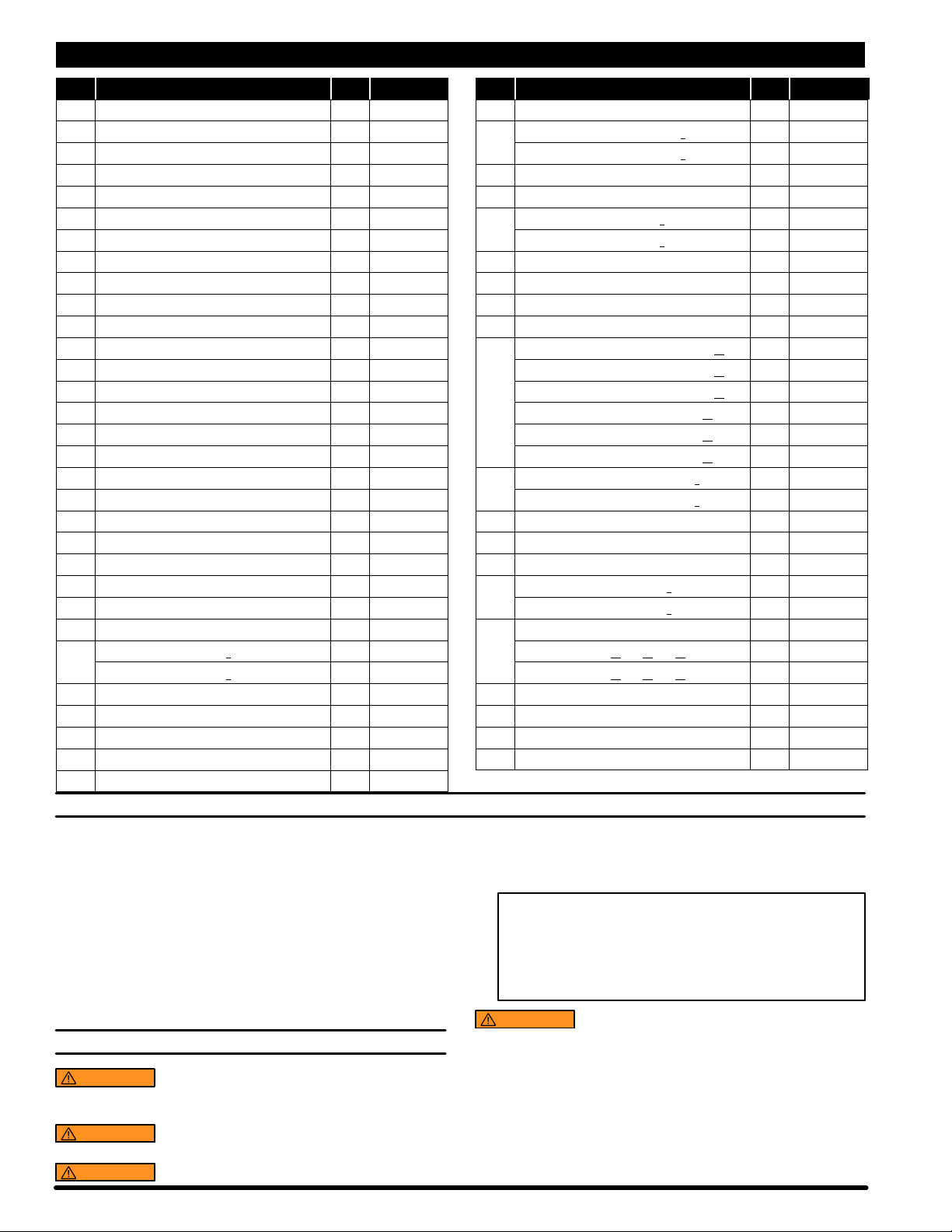
Item Description (size) (Qty) Part No. Item Description (size) (Qty) Part No.
1Bolt (4) 94333
2Upper Cap (1) 94307
n3 Track Gasket (2) 94311
4Sleeve (2) 94316
n5“O” Ring (1/16” x 11/16” o.d.) (4) Y325-15
n6“O” Ring (1/8” x 3/4” o.d.) (4) Y325-206
7 Spool (2) 94310
n8 “U” Cup (1/8” x 3/4” o.d.) (2) Y240-7
n9“O” Ring (0.106” x 0.587” o.d.) (2) 15066-PM
10 Muffler Housing (1) 94443
11 Cylinder (1) 94249
12 Retaining Ring (1) 94406
n13 “U” Cup (3/16” x 2” o.d.) (2) Y240-23
14 Piston (1) 94780
15 Lower Cap (1) 94308
n16 “O” Ring (1/8” x 1-3/8” o.d.) (1) Y325-216
17 Bushing (1) 94332
n18 Packing (1/4” x 1-5/8” o.d.) (1) 97181
n19 “O” Ring (3/32” x 1” o.d.) (1) Y325-117
20 Piston Rod (1) 94779
21 Groove Pin (3/16” o.d. x 1-1/8” long) (1) 94338
22 Spring (1) 94705
23 Ball (3/4” dia.) (1) Y16-224
24 Inner Check (1) 94279
n25 “O” Ring (3/16” x 1-7/16” o.d.) (1) Y327-319
26 Base - models LM2203A-( )1-C4 (1) 96253
- models LM2203A-( )2-C4 (1) 96253-1
27 Nut (4) 93828
n28 Copper Gasket (1) 96031
29 Tube (1) 94314-1
n30 “O” Ring (3/32” x 1-9/16” o.d.) (1) Y327-126
31 Ball (1” dia.) (1) Y16-232
32 Ball Stop Pin (0.187” dia. x 1.430” long) (1) 94339
33 Foot Valve - models LM2203A-( )1-C4 (1) 94315
- models LM2203A-( )2-C4 (1) 94315-1
n34 “O” Ring (1/16” x 7/16” o.d.) (1) Y325-11
n35 “O” Ring (1/16” x 3/4” o.d.) (1) Y325-16
36 Adapter - models LM2203A-( )1-C4 (1) 94447
- models LM2203A-( )2-C4 (1) 94447-1
37 Foam Liner (2) 94402
38 Ground Screw (#10 - 32 x 1/4”) (1) 93005
39 Bung Assembly (includes items 40 and 49) (1) 67145-3-B
40 Thumb Screw (1/4” - 20 x 1-1/2”) (1) Y197-158-C
41 Pipe Extension - models LM2203A-31-C4 (1) 94523-3
3/4 - 14 N.P.T. x 30-1/8” - models LM2203A-41-C4 (1) 94523-4
3/4 - 14 N.P.T. x 37-3/4” - models LM2203A-51-C4 (1) 94523-5
Rc 3/4 (3/4 - 14 BSP taper x 20-3/8”) - LM2203A-32-C4 (1) 94537-3
Rc 3/4 (3/4 - 14 BSP taper x 30-1/8”) - LM2203A-42-C4 (1) 94537-4
Rc 3/4 (3/4 - 14 BSP taper x 37-3/4”) - LM2203A-52-C4 (1) 94537-5
42 Valve Housing - models LM2203A-( )1-C4 (1) 94535
- models LM2203A-( )2-C4 (1) 94535-1
43 Ball Guide (1) 77904
44 Ball (1” dia.) (1) Y16-232
n45 “O” Ring (3/32” x 1-7/16” o.d.) (1) Y325-124
46 Ball Seat - models LM2203A-( )1-C4 (1) 94534
- models LM2203A-( )2-C4 (1) 94534-1
47 Valve Assembly (includes items 42 thru 46)
models LM2203A-31-C4, -41-C4, -51-C4 (1) 67085
models LM2203A-32-C4, -42-C4, -52-C4 (1) 67085-1
48 Washer (1) 94515
49 Nut (1/4” - 20) (1) Y12-4-C
n(1) 94833
nParts in Repair Kit 637481
GENERAL DESCRIPTION
Model LM2203A-X-C4 series two-ball double acting pumps are in-
tended to be used primarily for oiltransfer and delivery systems. It is best
to use this pump with low -- medium viscosity fluids. It uses carbon steel
and other materials which make it compatible with most petroleum
based lubrication products. The two-ball design provides better priming
of the lower foot valve. Double acting pumps will deliver material onboth
the up and down stroke.
NOTE: If this pump was purchased separately (not part of a system),
consult your sales representative for compatible dispensing accesso-
ries which will best match the application. All accessories must be able
to withstand the maximum pressure developed by the pump.
OPERATING AND SAFETY PRECAUTIONS
WARNING READ THE GENERAL INFORMATION MANUAL
INCLUDED FOR ADDITIONAL OPERATING AND SAFETY PRE-
CAUTIONS AND OTHER IMPORTANT INFORMATION.
WARNING STATIC SPARK. Can cause explosion resulting in
severe injury or death. Ground the pump and pumping system.
WARNING EXCESSIVE INLET PRESSURE. Can cause ex-
plosion resulting in severe injury or death. Do not exceed maxi-
mum operating pressure of 450 p.s.i. (31.0 bar) at150 p.s.i. (10.3
bar) inlet air pressure. Do not run pump without using a regula-
tor to limit air supply pressure to the pump.
PUMP RATIO X
INLET PRESSURE TO PUMP MOTOR =MAXIMUM PUMP
FLUID PRESSURE
Pump ratio is an expression of the relationship between the pump motor area and
the lower pump end area. EXAMPLE: When 150 p.s.i. (10.3 bar) inlet pressure is
supplied to the motor of a 3:1 ratio pump it will develop a maximum of 450 p.s.i.
(31.0 bar) fluid pressure (at no flow) -- as the fluid control is opened, the flow rate
will increase as the motor cycle rate increases to keep up with the demand.
WARNING EXCESSIVE MATERIAL PRESSURE. Can cause
equipment failure resulting in severe injury or property damage.
Do not exceed the maximum material pressure of any compo-
nent in the system.
NOTICE: Thermal expansion can occur when the fluid in the materi-
al lines is exposed to elevated temperatures. Example: Material
lines located in a non-insulated roof area can warm due to sunlight.
Install a pressure relief valve in the pumping system.
Replacement warning label (pn 94520) is available upon request.
Gadus S2 U1000 Grease Packet
LM2203A-X-C4 Page3of4
PARTS LIST / LM2203A-XX-C4
1
2
3
4
6
8
9
12
13
14
15
16
17
18
19
21
22
23
24
25
26
27 ,
28 H
29 ,
30
31
32
7
5
11
7
8
9
6
13
3
33 ,
20
Figure 2
.TORQUE REQUIREMENTS ,
(27) 80 in. lbs (9 Nm).
(29, 33) 95 - 100 ft lbs (128.8 - 135.6 Nm).
(36) 80 in. lbs (9 Nm) maximum.
5
4
10
34
35
.36
37
41
42
43
44
45
46
49
39
LOWER SECTION
UPPER SECTION
38
47
48
40
H
H
Lubricate with Gadus S2 U1000 grease at assembly.
PN 97999-1481
LM2203A-X-C4Page4of4
PLACING INTO SERVICE
AIR AND LUBRICATION REQUIREMENTS
Filtered air will help extend the life of the pump, allowing the pump to op-
erate more efficiently and yield longer service life to moving parts and
mechanisms.
•Install an air line filter to provide good quality clean and dry air. Install
it up stream from the regulator.
•Use an air regulator on the air supply to control the pump cycle rate.
Install the regulator as close as possible to the pump.
•In most installations, lubrication is not required. If the pump needs to
have lubrication, install an air line lubricator and supply it with a good
grade of non-detergent oil or other lubricant compatible with Nitrile
seals and set at a rate not to exceed one drop per minute.
INSTALLATION
•Mount and secure the pump as required for the application.
•Attach a ground wire from the pump ground screw to a suitable
ground.
•Connect a fluid hose to the pump outlet. In most cases a pipe sealant
should be used on thread connection. Tighten all fittings. Use cau-
tion not to damage threads.
OPERATION
START-UP
1. Turn the air regulator to “0” pressure setting.
2. Immerse the lower pump end into the material.
3. Open the dispensing device.
4. Start the pump cycling slowly by raising the pressure to 20 - 30 p.s.i.
(1.4 - 2.1 bar).
5. Close the dispensing device. Allow the pump to stall and build line
pressure. Check for any leaks and tighten fittings as needed. Adjust
pressure as required for the application.
SHUTDOWN
•Disconnect the air supply from the pump if it is to be inactive for a few
hours. Open the dispensing device to relieve line pressure.
SERVICE
PUMP DISASSEMBLY / REASSEMBLY
NOTICE: The unique design of this pump allows for quick basic pump
service without total removal from the drum (refer to the views below).
DISASSEMBLY - All threads are right hand. Refer to figure 2. These
proceduresare forthe installationof repair kitparts. Disconnectair
supply and relieve all system pressure prior to servicing. Carefully
remove the parts, inspect parts for damage, nicks or excessive wear and
determine if any parts will need replacement.
Follow the three disassembly steps in the detail views below and place
the pump on a clean bench.
1. Remove (1) bolts. Remove (18) packing, (17) bushing and (16) “O” ring.
2. Remove (36) adapter, releasing (10) muffler housing.
3. Grasp the (11) cylinder and remove the (20, 14) piston assembly.
4. Remove (15) lower cap and (3) track gasket. Remove (12) retaining
ring and (48) washer, then pull (14) piston off (20) piston rod.
5. Remove (2) cap and (3) track gasket. Push on the large o.d. end of
the (7) spool to remove the (4) sleeve. Grab thenose of (7) spool and
pull out. Repeat for other sleeve and spool.
REASSEMBLY - Thoroughly clean and lubricate all seals and
bores with Shell upon assembly. Replace all soft
parts with new ones included in the repair kit.
Note: Refer to the illustration (figure 2) for “U” cup lip seal direction.
1. Replace the seals on both the (7) spools and (4) sleeves.
2. Locate the valve chamber on the (11) cylinder where the 3/8’’ dia.
hole is located and install one of the (4) sleeves. Insert the (7) spool
from the opposite end. Next, install the remaining sleeve and spool.
3. Replace the (3) track gasket and install (2) cap.
4. Replace the (13) piston “U” cups (refer to figure 2 for proper orienta-
tion). Replace the (19) “O” ring and assemble (14) piston to (20) pis-
ton rod and retain with (48) washer and (12) retaining ring.
5. Install the (20, 14) piston assembly using great care to collapse the
outer lip of the second “U” cup, allowing it to slip into the cylinder.
6. Replace the (3) track gasket and install the (15) cap. Install the (16)
“O” ring onto the piston rod, replace (17) bushing and (18) packing.
7. Replace the (25) “O” ring and re-attach the (24) inner check.
8. Slide the pump assembly back into the (26) base / lower pump sec-
tion. Press the sections together and align the air inlet and pump out-
let as required and replace the four (1) bolts and (27) nuts (tighten to
80 in. lbs (9 Nm).
TROUBLE SHOOTING
If the pump will not cycle or will not deliver material.
•Be certain to check for non-pump problems including kinked, restric-
tive or plugged inlet / outlet hose or dispensing device. Depressurize
the pump system and clean out any obstructions in the inlet / outlet
material lines.
•Check all seals, including track gaskets.
•Check direction of “U” cup lips.
C) Unlock the (24) inner
check from the piston
rod.
Figure 5
Figure 4
B) Grasp the lower motor cap
and pull out the motor and
upper section of the lower
section.
PUMP DISASSEMBLY DETAIL
Figure 3
A) Remove the four
nuts from the base
of the Air Motor.
Gadus S2 U1000

This manual suits for next models

4

Other Ingersoll-Rand Water Pump manuals

Ingersoll-Rand ARO PE30 C0S Series User manual

Ingersoll-Rand

Ingersoll-Rand ARO PE30 C0S Series User manual

Ingersoll-Rand ARO 650717-C User manual

Ingersoll-Rand

Ingersoll-Rand ARO 650717-C User manual

Ingersoll-Rand 5696-1 User manual

Ingersoll-Rand

Ingersoll-Rand 5696-1 User manual

Ingersoll-Rand ARO 666300 C Series User manual

Ingersoll-Rand

Ingersoll-Rand ARO 666300 C Series User manual

Ingersoll-Rand ARO PD10E Series User manual

Ingersoll-Rand

Ingersoll-Rand ARO PD10E Series User manual

Ingersoll-Rand 650866-XXX-B User manual

Ingersoll-Rand

Ingersoll-Rand 650866-XXX-B User manual

Ingersoll-Rand ARO 612729 User manual

Ingersoll-Rand

Ingersoll-Rand ARO 612729 User manual

Ingersoll-Rand 6661HX-XXX-C User manual

Ingersoll-Rand

Ingersoll-Rand 6661HX-XXX-C User manual

Ingersoll-Rand ARO CL0409A91 Series User manual

Ingersoll-Rand

Ingersoll-Rand ARO CL0409A91 Series User manual

Ingersoll-Rand ARA AF0475L Series User manual

Ingersoll-Rand

Ingersoll-Rand ARA AF0475L Series User manual

Ingersoll-Rand PD10E-X-X User manual

Ingersoll-Rand

Ingersoll-Rand PD10E-X-X User manual

Ingersoll-Rand 6662AX-X-C User manual

Ingersoll-Rand

Ingersoll-Rand 6662AX-X-C User manual

Ingersoll-Rand ARO S237-SA User manual

Ingersoll-Rand

Ingersoll-Rand ARO S237-SA User manual

Ingersoll-Rand MP PUMPS CHEMFLO 1 User manual

Ingersoll-Rand

Ingersoll-Rand MP PUMPS CHEMFLO 1 User manual

Ingersoll-Rand ARO EP20 Series User manual

Ingersoll-Rand

Ingersoll-Rand ARO EP20 Series User manual

Ingersoll-Rand ARO PD10 Series User manual

Ingersoll-Rand

Ingersoll-Rand ARO PD10 Series User manual

Ingersoll-Rand ARO 66605J- Series User manual

Ingersoll-Rand

Ingersoll-Rand ARO 66605J- Series User manual

Ingersoll-Rand 6737X-XXX User manual

Ingersoll-Rand

Ingersoll-Rand 6737X-XXX User manual

Ingersoll-Rand ARO 670154-A User manual

Ingersoll-Rand

Ingersoll-Rand ARO 670154-A User manual

Ingersoll-Rand ARO 6662-C Series User manual

Ingersoll-Rand

Ingersoll-Rand ARO 6662-C Series User manual

Ingersoll-Rand PD05P series User manual

Ingersoll-Rand

Ingersoll-Rand PD05P series User manual

Ingersoll-Rand ARO 66610 Series User manual

Ingersoll-Rand

Ingersoll-Rand ARO 66610 Series User manual

Ingersoll-Rand NM2202A-11-731 User manual

Ingersoll-Rand

Ingersoll-Rand NM2202A-11-731 User manual

Ingersoll-Rand ARO 1875C Series User manual

Ingersoll-Rand

Ingersoll-Rand ARO 1875C Series User manual

Popular Water Pump manuals by other brands

Xylem Bell & Gossett e-80SC Series instruction manual

Xylem

Xylem Bell & Gossett e-80SC Series instruction manual

Regulus CSE TV ZV G70 3/4F Installation and operation manual

Regulus

Regulus CSE TV ZV G70 3/4F Installation and operation manual

SPIDO K 800 operating instructions

SPIDO

SPIDO K 800 operating instructions

Hypro 5200 Series Installation, operation, repair and parts manual

Hypro

Hypro 5200 Series Installation, operation, repair and parts manual

Walrus TP8-P Series instruction manual

Walrus

Walrus TP8-P Series instruction manual

DAB ACTIVE J 62 Instruction for installation and maintenance

DAB

DAB ACTIVE J 62 Instruction for installation and maintenance

EINHELL GH-PW 18 operating instructions

EINHELL

EINHELL GH-PW 18 operating instructions

Waterax B2X quick guide

Waterax

Waterax B2X quick guide

Stenner M128 Series Installation and maintenance manual

Stenner

Stenner M128 Series Installation and maintenance manual

Boyser DS-M Series operating instructions

Boyser

Boyser DS-M Series operating instructions

Steinbach SPS 50-1 ORIGINAL OWNER'S MANUAL

Steinbach

Steinbach SPS 50-1 ORIGINAL OWNER'S MANUAL

GORMAN-RUPP PUMPS JDV4A60-E2.7 200/3 Installation, operation and maintenance manual

GORMAN-RUPP PUMPS

GORMAN-RUPP PUMPS JDV4A60-E2.7 200/3 Installation, operation and maintenance manual

Pentair FREEFLO installation guide

Pentair

Pentair FREEFLO installation guide

Mindray BeneFusion uVP Instructions for use

Mindray

Mindray BeneFusion uVP Instructions for use

Pentair SC Series manual

Pentair

Pentair SC Series manual

Vivaria VarioTec N-4500 operating instructions

Vivaria

Vivaria VarioTec N-4500 operating instructions

ITT Industries Goulds Pumps 3656 Installation, operation and maintenance instructions

ITT Industries

ITT Industries Goulds Pumps 3656 Installation, operation and maintenance instructions

Hyundai SP9700 manual

Hyundai

Hyundai SP9700 manual

manuals.online logo
manuals.online logoBrands
  • About & Mission
  • Contact us
  • Privacy Policy
  • Terms and Conditions

Copyright 2025 Manuals.Online. All Rights Reserved.