Ingersoll 220 User manual

a
INGER[iOLL
224,222,224 and 444
Tractors
Operator's Manual No. 9-6412
rtrtt
LE}IC

I
IF THIS N{ACHINE IS USED BY AN EMPLOYEE OR IS
I,OANED OR RENTED, MAKE ABSOLUTELY CERTAIN
,I'IJAT''I'HE OPERA'I'OR(S), PRIOR TO OPERATING:
i. iS INSTRUCTED IN SAFE ANID PROPER USE.
2. ITEVIE\VS ;\ND UNDERSTANDS THE MANUAL(S)
pER'f ,\tNINIG 1'O THE NlACHINE. /51253
BE FOR E STARTING ENG IN E
STUDV OPERATOR'S MANIJAL SAFETY MESSAGES
READ AI-!- SAFETY SIGNS ON MACI-IINE
CLEAR THE AREA OF OTHEH PERSONS
LHARhI & PRACTICE SAFE USE CIF
COruTROI-S BE FOR E OPE RATIhIG
I' I5 VOUR R€SPONSIAIT IIV,TO UNDERSlAND ANO FOLLOW MANUFACTUR€R'S INSTRUC,IONS
oN MAcrirNE opERArroN. sE*vrcE, o"r, ,a,:oairir"e-iuur,"e^r LAws ANo REGULATToNs
opERATo,r AND sERVrcf MaNUAt-s "o, ac oeroi"ED FnoM youR EeurpMENr oEAr_En.

TABLE OF CONTENTS
INTRODUCTION ... 2
J
SERIAL NUMBERS AND PRODUCT IDENTIFICATION NUMBER
GENERAL SPECI FICA
Hydraulic System
Electrical. System
TIONS 4
4
4
I4
4
4
Brake
Transaxle
Speed Range
Wheels and Tires
ENGINE SPECIFICATIONS
OVERALL MEASUREMENTS
LUBRICATION
Engine Lubrication
Lubrication Chart
5
b
7- I
B- I
FUEL SPECIFICATIONS 10. 11
OPERATING INSTRUCTIONS. . .. 12.27
Operating Controls & Instruments 12 - 17
Pre-Starting Check List 18 - 19
Starting Procedure 20 - 21
Stopping the Engine 22
Operating Procedure 23 - 27
PREVENTI VE MAI NTENANCE
Brake Adjustment
Air Cleaner
Carburetor Adjustments
Steering Adjustment$
28- 40
29-30
31
32
1',I
34
35. 40
35
36
37. 38
Toe-ln Adjustments
Electrical System
Headlights
Spark Plugs
Storage Battery
Jump Start With Booster Battery
Wiring Diagram
ATTACHMENTS
?o
40
41

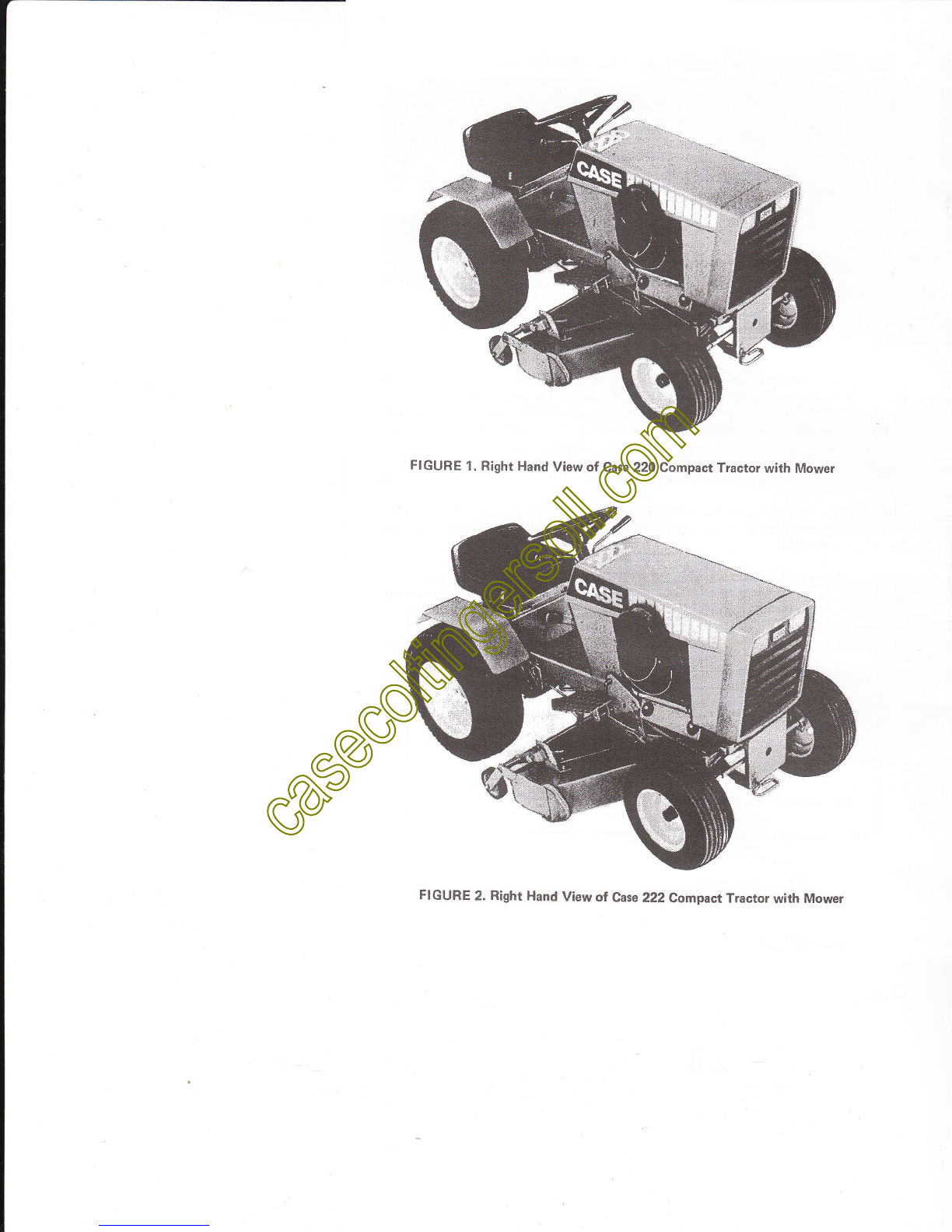
FIGURE 1. Right Hand View of Case 220 Compact Tractor with Mower
FIGURE 2. Right Hand View of Case 222 Compact Tractor with Mower

I
i
l
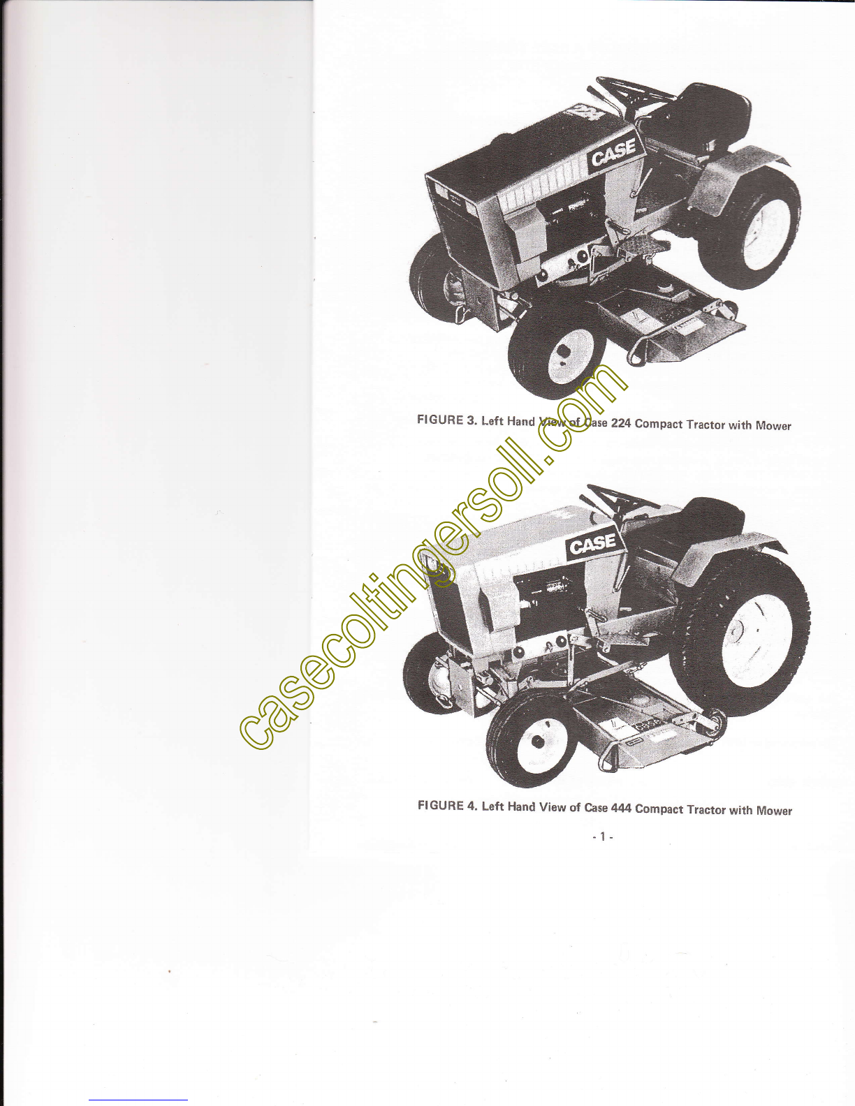
FIGURE 3. Left Hand View of Case 224 Compact Tracror with Mower
FIGURE 4. Left Hand view of case 444 compact Tractor with Mower
-1.

TO THE PURCHASER OF A CASE TRACTOR
The care you give your new Case Tractor will greatly determine the satisfaction and
service life you will obtain from it. Use this manual as your guide. By observing the in-
structions and suggestions in this manual, your Case Tractor will serve you well for many
yea rs.
As an Authorized Case Dealer, we stock Genuine Case Parts, which are manufactured
with the same precision and skills as the original equipment. Our factory trained staff is
kept well informed on the best methods of servicing case equipment and is ready and
able to help you.
Should you require additional aid or information. contact us.
g/*, -M2,,*./6*' 9"-a
NOTICE
Laws of some states or provinces may require that this unit be equipped with a SPARK
ARRESTOR OR SPARK ARRESTING MUFFLER. The State of California. as an
example, is one state which has such regulations for agricultural and forestry applications,
plus a regulation for construction applications in forest-covered, brush-covered, or
grass-covered lands.
Typically such laws and reguiations require spark arresting devices to be maintained in
good working order and typically to be attached to the exhaust system of naturally
aspirated engines (engines without a turbo charger).
CANADIAN RADIO INTERFERENCE REGULATIONS
The Canadian Government, under authority granted by the Radio Act, has pro.
mulgated regulations covering this gasoline powered case compact Tractor if im.
ported into Canada on or after September 1. 1976
The spark plug{s) in this machine when replaced must have a resistor type spark plug
i nstal I ed.
The certif ication label applied to the engine must not be removed or obliterated.
2-79-SL-6000 u.s. PRtcE $1.40 PRINTED IN U.S.A.
- z-

PRODUCT IDENTIFICATION NUMBER (PIN)
AND
SERIAL NUMBERS
When ordering parts.from your Authorized Case Dealer and in all contacts or cor-
respondence with your dealer relative to the tractor, always specify the Product ldentifi-
cation Number and the Model Number of your tractor and the Model and Serial Numbers
of the engine.
The Tractor Model and Product ldentification Numbers are stamped on the number
plate located on the instrument panel, Figure 5. The Engine, Model, Serial and Engine
Specif ication Numbers are stamped on a plate fastened to the right or upper f ront side of
the engine, Figure 6.
This Manual applies to the following tractors:
Model Product ldentification Number and After
22Q
222
224
444
TRACTOR MODEL AND , -.-li
PRODUCTTDENTIFICATION i,
NUMBEHS ',..o {:
FIGURE 5
9734870
9736998
9734870
9739739
NOTE: The terms "Right Hand", "Left Hand", "Front" and "Rear"
whenever used in this manual apply to the tractor when facing in the
direction the tractor will move in forward operation.
For reference, fill in the Product ldentification Number, Model Number and Engine
Numbers of your tractor in the spaces provided below.
Tractor Model Number
Tractor Product
Number (PlN) ldentif ication
Engine Model Number
Engine Serial Number
Engine Specif ication Number 6
FICATION NUMBER
FIGURE 6.

G ENERAL SPECI FICATIONS
HYDRAULIC SYSTEM
Independent 6 quart (5.71 l) reservoir, pump, control valve, hydraulic motor and heat
exchanger. Pump delivers approximatery g gailons per minute (36 r/min.) at3600 RpM.
Maximum drive system operating pressure {relief valve} setting: 2000 psi (13g00 kpa}.
Maximum attachment lift system operating.pressure setting: b75 psi (3g70 kpa).
ELECTRICAL SYSTEM
Type of System
Battery
Headlights
Starter
Flywheel Alternator
12 Volt, Negative Ground
Case, 24 Ampere Hour at 20 Hour Rate
12 Volt
12 Volt, Bendix Drive
12 Volt, 15 Amp
BRAKE
Type Double acting, self energizing, meehani-
cal contracting band, with the drum
shaft driven from transmission dif-
ferential. Includes parking lock.
TRANSAXLE
TYPe.. ....Hydraulic Driven,
Differential Automotive Type
Oil Capacity 3 Ouarts(2.8 l)
Dual Gear Range
Bevel Gear
SPEED RANGE
220,222 Low
and 224 High
444 Low
Hish
WHEELS AND TIRES
Tire Size
6.50-8
8.50-12
8.00-16
FORWARD
0 to 3.0 MPH (4.8 km/h)
0 to 7.3 MPH {1 1.75 km/h}
0 to 3.2 MPH (5.15 km/h)
0 to 7.8 MPH (12.55 km/h)
REVERSE
0 to 3.0 MPH (4,8 km/h)
0 to 7.3 MPH (1 1.75 km/h)
0 to 3.2 MPH (5.15 km/h)
0 to 7.8 MPH (12.55 km/h)
PLY TYPE
2 Front
High Flotation
2 Rear
High Flotation
2 Rear
High Flotation
Recommended Pressure Max. Pressure
PSI (kilopascal) PSI (kilopascal)
8 (55) 14 (e7)
I (55) 1o t69)
8 (55) 14 (e6)
-4-

ENGINE SPECIFICATIONS
GENERAL
Type . .
Model .
Cycle . .
Cylinoers
Cylinder Bore .
Stroke .
Piston Displacement .
Horsepower
Compression Ratio . .
Full Load Speed .
No Load Speed .
ldle Speed
Valve Clearance Cold (lntake) .
Valve Clearance Cold {Exhaust)
no
Kohler
K241AS
4
I
3-114in. (82.6 mm)
2-718 in. (73.0 mm)
23.9 in.3(392 cm3)
10 HP (7.46 kw)
6to 1
35OO RPM
3600 BPM
lOOO RPM
.010 in. {0.25 mm)
.020 in. {0.50 mm} .010 in.(0.25 mm) .010 in.(0.25 mm)
.020 in.(0.50 mm) .020 in.(0.50 mm)
3-3i8 in.(85.7 mm} 3-1/2 in.(88.9 mm)
3-114 in.(82.6 mm) 3-1l4 in.(82.6 mm)
2g.o7 in.3p;76.rn3) 3i.zz in.31511 ".3y
12 HP(8.95 kwl 14 HP.(10.44 kw)
222
Kohler
K301AS
4
1
6to 1
35OO RPM
3600 RPM
lOOO RPM
224 & 4ar,
Kohler
K321AS
1
6to l
35OO RPM
3600 RPM
lOOO RPM
PISTON AND CONNECTING ROD
Piston
Compression
Oil Rings
Connecting Rod . .
FUEL SYSTEM
Carburetor
Filter Screen
Fuel Tank Capacity
IGNITION SYSTEM
Breaker Point Gao
lgnition Timing
Spark Plug
Thread
Gap
COOLING SYSTEM
Flywheel Blower .
Rings. Aluminum
'>
1
Aluminum
1" SAE Flange
In tank outlet fitting
3 Gallons (11.4 l)
-020 in. (0.50 mm)
SP Mark (20o BTDC)
Prestofite 14 L7 or equivalent
(Prestolite 14RL7 or equivalent in Canada)
14MM
.025" (0.64 mm)
Forced air with baffles directing air
around finned cylinder and head area.

A Overall Length
B Wheel Base
C Overall Height
D Hood Height - Rear
E Minimum Ground
Clearance at Gear Case
Bear Wheel Tread
Front Wheel Tread
Overall Width
Shipping Weight
OVERALL MEASUREMENTS
FIGURE 7,
220,222 & 224
65" (1650 mm)
46" (1170 mm)
40" (1020 mm)
35-'t/2" (900 mm)
7-118" 1180 mm)
27-314" (700 mm)
28-314" (730 mm)
37" (940 mm)
715 lbs. (325 kg)
444
70" (1780 mm)
46" (1170 mm)
43-112" (1100 mm)
38-1/2" {980 mm)
11" (280 mm)
31-112" (800 mm)
33-112" (850 mm)
41" (1040 mm)
770 lbs. (350 kg.)
-T
E
{
-6-

LUBRICATION
ENGINE LUBRICATION
SELECTION OF OIL
It is extremely important that you select and use a detergent type, high quality, sE or
CC, API Service Classification Oil such as Case HDM.
OIL SAE VISCOSITY RATING
SAE 30 or 20W-40 . Air Temperatures 30o F (-1o C) and Above
SAE 10W-30 .. . . . AirTemperatures0o F (.1BoC) to30o F (-.loC)
SAE 5W-20 Air Temperatures 0o F (-1Bo C) or Below
OIL CHANGE
Drain and refill the crankcase at least after every 2E hours of operation.
lf possible, run engine just prior to changing oil--the oil will flow more f reely and carrv
away a greater amount of contaminant when hot.
lf the engine service is severe - (frequent stopping and starting, high or low operating
temperature) - the crankcase should be drained more often to prevent the formation of
sludge or harmful deposits in the enqine.
IMPORTANT
1. when thecrankcase isdrained, refillwith 3 measured pints (1.4 llof oil.
operate the engine for a few minutes, allow sufficient time for the oil to run down off
the engine parts, then check the oil level with the dipstick.
This will prevent overfilling or underfilling the crankcase, either of which can be
detrimental to the engine service life and will give you false oil consumption records.

LUBRICATION CHART
FIGURE 8.
-8-

Front Wheel Bearings
Blower Screen & Heat
Front Axle Pivot Pin
Lever & Brake Linkage
Travel and Lift Lever and Li
Hydraulic Oil +
Air Cleaner Element *"*
SERVICE POINTS
HOURS
UN
DAI LY
HOU RS
OF
WEEKLY
HOURS
OR
MONTHLY
HOURS
OR
YEARLY
*Always check engine oil level before each use of tractor.
Keep oil level between marks on dipstick. See page 16 for engine lubrication
recommendations. Capacity 3 pts. {1.4 l)
**Be sure there are no leaks between gaskets, joints at carburetor, air cleaner and
cylinder block.
***More often in dustv conditions.
oClean and regap
+Hydraulic System: Use SAE 5W-20 motor oil in winter (below 32oF (0oC)). Use
SAE 20W-40 motor oil in summer. Use API Service Classification SE or CC motor
oil. The hydraulic reservoir filler cap is located just to the left of the battery. The
oif level must be maintained at 5" to 6" (12O mm to 150 mm) down from the f il-
ler. Overfilling will result in oil leakage from the till cap, underfilling will result in
erratic operation. The oil drain pl.ug is a 114" allen plug on the underside of the
travel valve inlet port.
Transmission: Use SAE 2GW-40 motor oil or SAE 80 EP gear lube in the transmis-
sion the year round.
Grease Fittings: Use number 1 gun grease (Lithium Base) for all pressure fittings (as
many strokes as required).

FUEL SPECIFICATIONS
. 10-

GASOLINE
CARBURETION ON SMALL GASOLINE ENGINES IS ALWAYS CRITICAL OF
DIRT. IT IS BECOMMENDED THAT A FILTERING FUEL FUNNEL ALWAYS BE
USED ALONG WITH CLEAN GASOLINE.
AT ANY EVIDENCE OF FUEL STARVATION, CLEAN THE FILTER IN THE
TANK OUTLET FITTING.
DO NOT MIX OIL WITH GASOLINE FOR THIS ENGINE.
Engines used in case Tractors are designed to operate on REGULAR or UN-
LEADED GRADE gasoline having a minimum research merhod rating of g0.7 octane.
This will give full power and economy together with long engine life and low mainten.
ance cosr.
The typical Octane number ratings for regular grade gasoline (March 1g67).
Motor Method
Research Method
Average
86.2 Octane Number
_pl=Z Octane Number
90.2 Octane Number
These two Octane ratings are used to define the anti-knock quality of gasoline. lt
has become common practice in the Petroleum Industry to refer only to the RESEARCH
METHOD RATING although in the United States the average of the two figures is posted
on gasoline pumps.
when only one octane rating is given for gasoline and the rating method is not
specified, it can be assumed to be the average rating in the United States or the Research
Method Rating elsewhere in.the World.
11

OPERATI NG INSTRUCTIONS
OPE RATI NG CONTROLS AND INSTRUMENTS
FIGURE 11
't. IGNITION KEY AND STARTER SWITCH
TO START: Turn key to right and hold (,,START,,position)
TO RUN: Release key to ,,RUN.'position wfien engine starts
TO STOP: Turn key to left (',OFF.,positionl
- 12.

2. CHOKE
TO CLOSE CHOKE: Push choke leverforward. Closechoke to start4 cold engine.
TO OPEN CHOKE: Pullchoke lever rearward. Open choke slowly after engrne starts.
choke should be open during normal operation or when starting a warm engine.
3, THROTTLE
TO IDLE ENGINE: Pull throttle lever rearward. ldle engine when starting and when
cooling engine before stopping.
TO INCREASE ENGINE SPEED: Push throttle lever forward until desired engine
speed is obtained.
Reduce engine speed during operation to obtain maximum fuel economy but not
low enough to cause engine lug-down (or labor) which will result in overheatino.
4. TWO SPEED TRANSAXLE
TO SELECT LOW RANGE: Place travel control levet in neutral.
Bring tractor to a complete stop.
Pry lever torward slightly to clear neutral locating pin.
Pull lever up past the neutral locating pin and release.
TO SELECT NEUTRAL: Place travel control lever rn neutral.
Bring tractor to a complete stop.
Pry lever forward slightly to clear neutral locating pin.
Engage hole in lever over neutral locating pin and release.
TO SELECT HIGH RANGE: place travel control lever in neutral.
Bring tractor to a complete stop.
Pry lever forward slightly to clear neutral locating prn.
Push lever down past the neutral locating pin arrd release.
- tJ -

Range gears may not shift readily when selecting.
Rotate the gears to allow them to shift.
To rotate gears:
1. move travel control lever partway into forward.
2. return travel control lever to neutral.
IMPORTANT: Range shift lever must be positioned past the neutral locating pin when
in Low or High range. Gear damage will result if lever is not positioned
properly.
5. TRAVEL CONTROL LEVER
TO STOP TRAVEL: Position travel control lever in neutral.
TO TRAVEL FORWARD: Slowly and in small increments move travel control lever
f orward.
Speed and power will increase as the lever is moved from the neutral position to-
ward the full forward position.
To TRAVEL REVERSE: slowly and in small increments move travel control lever
rearward.
Speed and power will increase as the lever is moved from the neutral position to.
ward the f ull reverse position.
DO NOT TRAVEL FULL SPEED IN REVERSE.
TO "RETARD" TRAVEL lN FORWARD OR REVERSE: "Retard" is the hill holdins
or dynamic braking position for the travel control lever.
Position travel control lever in "Retard" when descending a hill or incline.
See Operating Procedure Section of this manual for more complete description of
"Retard" usage.
Depress the travel control lever slightly when moving to either direction for smoother
motion and control.
14-
4q FIGURE 12

The travel control lever automatically returns to neutral when the brake is applied. The
travel control lever can be moved.from the neutral position with the brake applied.
A neutral start switch is actuated by the travel control lever. The lever must be in the
neutral position to start the engine.
6. BRAKE PEDAL
TO BRAKE: Depress brake pedal fully.
This action will return the travel control lever to neutral and bring rractor to an
abrupt stop.
NOTE: This method of stopping should be avoided.
Use this method for emergency stopping only.
The tractor should be brought to a smooth stop by srowry returnrng the travel
control lever to neutral.
Depress brake pedal fully if positioning the travel control lever in neutral does
not bring the tractor to a stop.,
See Operating Procedure Section of this manual for more complete discussion of stop-
ping travel.
15 -
FIGURE 13

7. PARKING BRAKE LOCK
TO SET: Depress brake pedal fully.
Push down on the parking brake lock so one of the notches engages with the bot.
tom of the slot.
TO RELEASE: Depress brake pedal slightly and release.
A spring will disengage the parking brake lock.
HEADLIGHTS
TO LIGHT: Turn key to the "LIGHTS" position after engine is started.
Using lights with engine off or at low idle will result in a discharged battery.
TO EXTINGUISH: Turn key from the "LlGHTS" position.
9. AMMETER
The ammeter indicates rate of charge to the battery. The ammeter reading will be rela-
tively high when the battery is discharged or when the engine is first started.
The ammeter reading will gradually fall back to zero as the battery charges.
Stop tractor and have cause corrected if:
a. Ammeter remains at "0" when battery is dischargedor
b. if ammeter continuously reads high.
8.
l6
.. t-
'ii:;i-1i|/=
itii*s$$
'ti'l+
FIGURE 14
This manual suits for next models
3
Table of contents
Other Ingersoll Tractor manuals