User Manual Ver. 1
WiFi RF Specification
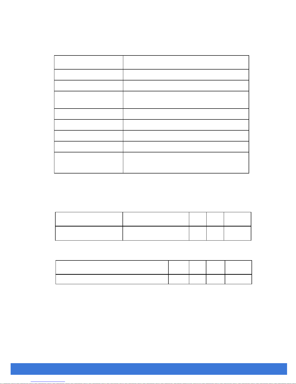
RF Specification
Conditions : VDD=3.3V ; Temp:25°C
IEEE 802.11b/g/n, WiFi compliant
2.400 GHz ~ 2.484 GHz (2.4 GHz ISM Band)
802.11b : CCK, DQPSK, DBPSK
802.11 g/n : OFDM /64-QAM,16-QAM, QPSK, BPSK
802.11b /11Mbps : 15 dBm ± 2 dB , typical @ EVM ≤ -9dB
802.11g /54Mbps : 13 dBm ± 2 dB , typical @ EVM ≤ -25dB
802.11n /65Mbps : 12 dBm ± 2 dB , typical @ EVM ≤ -28dB
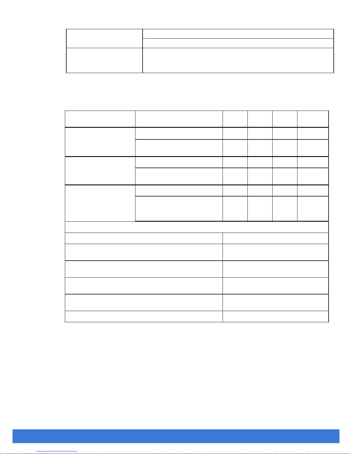
Receive Sensitivity
(11n,20MHz)
@10% PER
- MCS=0 PER @ -85dBm, typical
- MCS=1 PER @ -84dBm, typical
- MCS=2 PER @ -82dBm, typical
- MCS=3 PER @ -80dBm, typical
- MCS=4 PER @ -77dBm, typical
- MCS=5 PER @ -73dBm, typical
- MCS=6 PER @ -71dBm, typical
- MCS=7 PER @ -69dBm, typical
Receive Sensitivity
(11g) @10% PER
- 6Mbps PER @ -86dBm, typical
- 9Mbps PER @ -85dBm, typical
- 12Mbps PER @ -85dBm, typical
- 18Mbps PER @ -83dBm, typical
- 24Mbps PER @ -81dBm, typical
- 36Mbps PER @ -78dBm, typical
- 48Mbps PER @ -73dBm, typical
- 54Mbps PER @ -72dBm, typical
Receive Sensitivity
(11b) @8% PER
- 1Mbps PER @ -90dBm, typical
- 2Mbps PER @ -89dBm, typical
- 5.5Mbps PER @ -88dBm, typical
- 11Mbps PER @ -85dBm, typical
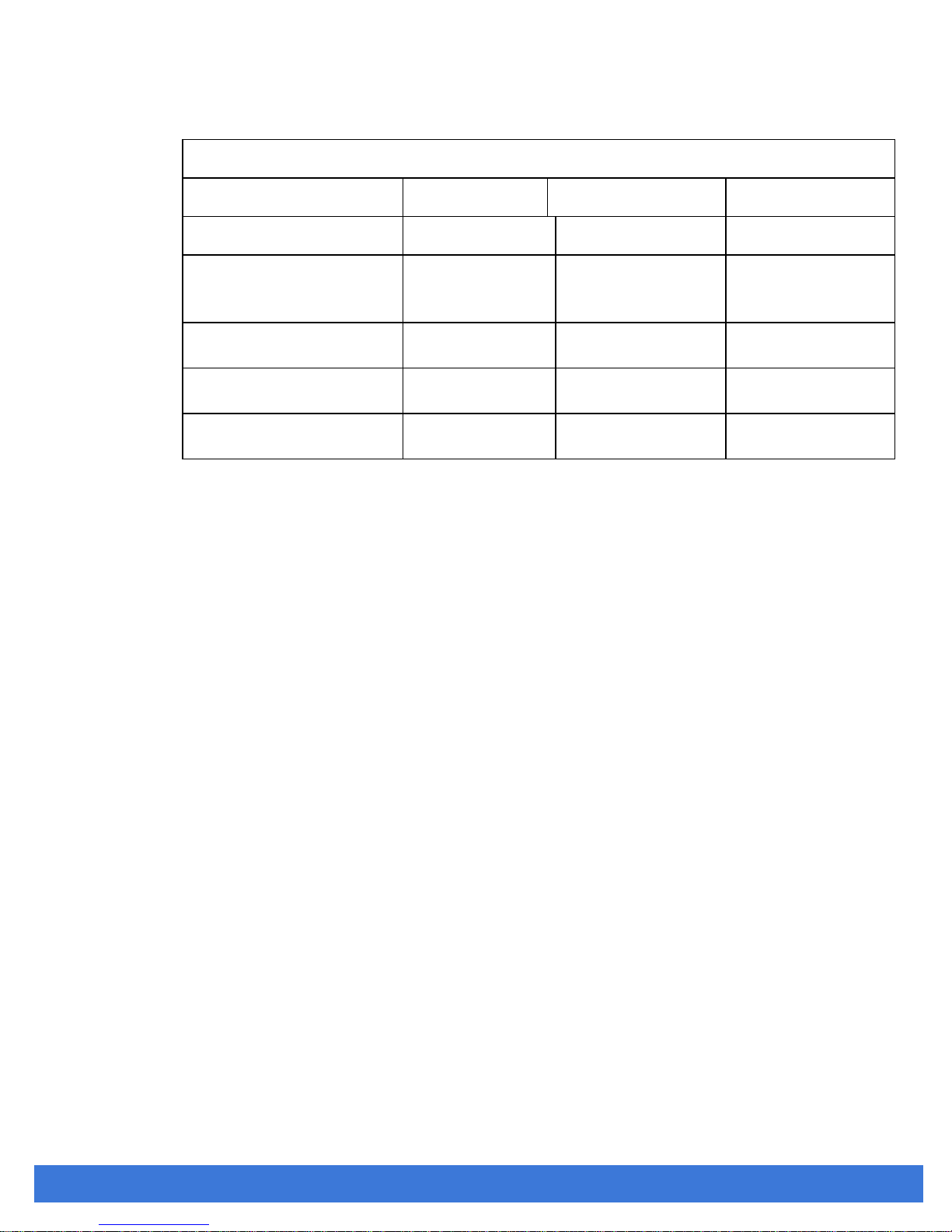
802.11b : 1, 2, 5.5, 11Mbps
802.11g : 6, 9, 12, 18, 24, 36, 48, 54Mbps
Data Rate
(20MHz,Long
GI,800ns)
802.11n: 6.5, 13, 19.5, 26, 39, 52, 58.5, 65Mbps
Data Rate
(20MHz ,short
GI,400ns)
802.11n: 7.2, 14.4, 21.7, 28.9, 43.3, 57.8, 65,72.2Mbps
INGICS TECHNOLOGY CO., LTD. • [email protected] • WWW.INGICS.COM