Ziton ZP3-ECU User manual

ZP3-ECU Extinguishing
Control Unit User Guide
P/N 503-0800ZE-U-03 • REV 03 • ISS 20MAR14

Copyright
© 2014 UTC Fire & Security. All rights reserved.
Trademarks and
patents
The ZP3-ECU Extinguishing Control Unit name and logo are
trademarks of UTC Fire & Security.
Other trade names used in this document may be trademarks or
registered trademarks of the manufacturers or vendors of the
respective products.
Manufacturer
UTC CCS Manufacturing Polska Sp. Z o.o.
Ul. Kolejowa 24. 39-100 Ropczyce, Poland
Authorized EU manufacturing representative:
UTC Fire & Security B.V.
Kelvinstraat 7, 6003 DH Weert, Netherlands
Certification
2002/96/EC (WEEE directive): Products marked with this symbol
cannot be disposed of as unsorted municipal waste in the European
Union. For proper recycling, return this product to your local supplier
upon the purchase of equivalent new equipment, or dispose of it at
designated collection points. For more information see:
www.recyclethis.info.
2006/66/EC (battery directive): This product contains a battery that
cannot be disposed of as unsorted municipal waste in the European
Union. See the product documentation for specific battery
information. The battery is marked with this symbol, which may
include lettering to indicate cadmium (Cd), lead (Pb), or mercury
(Hg). For proper recycling, return the battery to your supplier or to a
designated collection point. For more information see:
www.recyclethis.info.
Contact information
For contact information, see www.utcfssecurityproducts.eu.

ZP3-ECU Extinguishing Control Unit User Guide i
Content
Important information ii
Associated Publications and References ii
Preface iv
Limitations iv
Chapter 1 Introduction 1
System Overview 2
Chapter 2 Operating the System 7
Extinguishing Control Unit 8
Extinguishing Status Unit 17
Extinguishing Repeater Unit 18
Extinguishing Door Monitor Board 19
Chapter 3 Routine Maintenance 21
Daily Maintenance Checks 22
Weekly Maintenance 22
Quarterly Maintenance 23
Index 25

ii ZP3-ECU Extinguishing Control Unit User Guide
Important information
Limitation of Liability
To the maximum extent permitted by applicable law, in no event will UTCFS be
liable for any lost profits or business opportunities, loss of use, business
interruption, loss of data, or any other indirect, special, incidental, or
consequential damages under any theory of liability, whether based in contract,
tort, negligence, product liability, or otherwise. Because some jurisdictions do not
allow the exclusion or limitation of liability for consequential or incidental
damages the preceding limitation may not apply to you. In any event the total
liability of UTCFS shall not exceed the purchase price of the product. The
foregoing limitation will apply to the maximum extent permitted by applicable law,
regardless of whether UTCFS has been advised of the possibility of such
damages and regardless of whether any remedy fails of its essential purpose.
Installation in accordance with this manual, applicable codes, and the instructions
of the authority having jurisdiction is mandatory.
While every precaution has been taken during the preparation of this manual to
ensure the accuracy of its contents, UTCFS assumes no responsibility for errors
or omissions.
Advisory Messages
Advisory messages alert you to conditions or practices that can cause unwanted
results. The advisory messages used in this document are shown and described
below.
WARNING: Warning messages advise you of hazards that could result in injury
or loss of life. They tell you which actions to take or to avoid in order to prevent
the injury or loss of life.
Caution: Caution messages advise you of possible equipment damage. They tell
you which actions to take or to avoid in order to prevent the damage.
Note: Note messages advise you of the possible loss of time or effort. They
describe how to avoid the loss. Notes are also used to point out important
information that you should read.
Associated Publications and References
The following document, or part thereof, is referenced from this manual: ZP3-
ECD Extinguishing Control Unit Display Board Installation Sheet, doc. no. 501-
0804ZE-1-03.

ZP3-ECU Extinguishing Control Unit User Guide iii
List of Abbreviations, Acronyms and Terms
Abbreviation Definition
DC Direct Current
Extinguishant Generic term to describe an extinguishing agent used to combat fires; for
example water, dry chemical, foam etc.
GND Ground
LCD Liquid Crystal Display
LED Light Emitting Diode
mA milliampere
PC Personal Computer
RX Receive
SW Switch
TX Transmit
V Volts

iv ZP3-ECU Extinguishing Control Unit User Guide
Preface
This manual is intended for use by the user of the Ziton ZP3 Extinguishing
Control System. It provides the information required to effectively operate the
Extinguishing Control System in all operating modes.
Limitations
Sensing Equipment Limitations
The Extinguishing Control System equipment is reliant on external detection
equipment such as detectors, call points and fire control panels in order to
activate effective fire alarms. Incorrect positioning of the detectors, limitations in
the detector itself or incorrect application can result in failure of the detection
process.
Power Faults
In the event of a mains fault the Ziton ZP Fire System can run off on board
batteries for approximately twenty four hrs depending on the loading of the
system. After this time, the Ziton ZP Fire Control System will no longer detect
fires and thus cause the Extinguishing Control System to be unable to extinguish
fires until such time as the mains power is returned.
Bells and Sirens
When the Extinguishing Control System causes an extinguishing discharge, the
appropriate fire bells and sirens sound. These could prove useless unless they
are situated in close proximity to the people they are supposed to alert.
Extinguishing System Design
The Extinguishing Control System only controls the extinguishing activating
circuits. The design of the piping nozzles extinguishing pressure etc. is the
responsibility of the extinguishing system design engineer.
Maintenance System
As with most extinguishing systems the most common cause of their malfunction
is lack of maintenance. A full maintenance plan should be carried out on a
regular basis as described under “Routine Maintenance” in Chapter 3 of this
manual (see page 27).

ZP3-ECU Extinguishing Control Unit User Guide 1
Chapter 1
Introduction
Summary
This chapter gives a general introduction to the ZP3-ECU system.
Content
System Overview 2
Control of Fire Extinguishing Systems 2
Extinguishing Status Unit 4
Extinguishing Repeater Units 5
Extinguishing Control Door Monitor Board 6

Chapter 1: Introduction
2 ZP3-ECU Extinguishing Control Unit User Guide
System Overview
Control of Fire Extinguishing Systems
The ZP Analogue Addressable Fire Detection System is ideally suited to
operating fire extinguishing systems that use an extinguishant such as foam, dry
chemical or powder to combat fires in any size area. Fire extinguishing systems
are extensively used to protect risks such as computer rooms, data storage,
transformers, electrical control rooms, file storage and, essentially, any area
where the use of water is inappropriate.
The nature of extinguishing systems imposes certain criteria upon the fire
detection and control equipment. These are needed to prevent accidental
discharge, audible alarms indicating alarm and discharge, time delays to allow
evacuation of personnel from the area, shutdown of equipment and ventilation,
and the closing of doors and shutters to prevent leakage.
The ZP Extinguishing Control System not only achieves these requirements, but
also includes the many advantages of advanced addressable analogue fire
detection.
A major feature of the system is that all functions are software controlled. All
actions carried out at the Extinguishing Control Unit, both automatic and manual,
are reported to the main ZP Fire Alarm Panel via the Addressable
communication line.
Figure 1: Extinguishing System Configuration

Chapter 1: Introduction
ZP3-ECU Extinguishing Control Unit User Guide 3
Extinguishing Control Unit
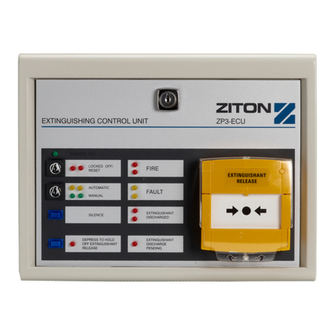
The Ziton ZP3-ECU Extinguishing Control Unit, see Figure 2, is designed to
connect to a ZP fire detection system, and control a fire extinguishing system. It
interfaces to the fire detectors of a ZP fire detection system, and provides secure
"coincidence connection" control of the extinguishing system.
The self-contained unit has key switches for automatic or manual selection, as
well as lock-off for maintenance. Other controls are a manual extinguishant
release, an alarm silence push-button, extinguishant hold off button and
indicators for automatic, manual, locked-off, fault, fire, extinguishant discharged
and reset status.
Outputs are provided for extinguishant release valves or actuators, audible fire
alarm sounders, separate extinguishant release sounders, visual exit signs, door
closing and shutter release. Also provided are facilities for remote manual
extinguishant release, and remote operation and status functions.
Extensive monitoring is provided for many functions, including power supply,
fuses, and operation. Field wiring is monitored for extinguishant release
valves/actuators, fire sounder, extinguishant sounder and manual extinguishant
release units.
Optional monitoring is provided for low extinguishant pressure, extinguishant
release verification, and locked/unlocked entry door status of the protected area.
The extinguishing control unit is under the control of its ZP fire control panel. It
communicates with the fire panel every two seconds, and reports the status of all
functions. A fault signal is raised at the fire panel for any out-of-normal condition,
which exists at the extinguishing control unit. The fire panel indicates the type of
fault, and where applicable, reports the condition to a building management
system. Remote status of each extinguishing control unit -automatic, manual,
fault, locked-off, or extinguishant discharged can be displayed at the ZP fire
control panel without additional wiring.
Each extinguishing control unit operates one fire extinguishing system. Any
number of extinguishing control units may be used on a ZP fire detection system,
with each unit requiring two system addresses. The system is field programmable,
with functions such as detector cross-mapping, automatic extinguishant release
delay, selection of delay/no delay for manual extinguishant release, and output
relay control being fully configurable.

Chapter 1: Introduction
4 ZP3-ECU Extinguishing Control Unit User Guide
Figure 2: Extinguishing Control Unit – External View
Extinguishing Status Unit
The Ziton ZP3-ECUS Extinguishing Status Unit, see Figure 3, is designed to
connect to a ZP3-ECU Extinguishing Control Unit.
The Extinguishing Status Unit has key switches to enable remote control of the
Extinguishing Control Unit for automatic or manual selection, as well as lock-off
for maintenance. Other controls are manual extinguishant release via the
callpoint, alarm silence push button, as well as an extinguishant hold off more
time button. Indicators mimic those on the Extinguishing Control Unit for
automatic, manual, locked-off, extinguishant discharged and reset status.
Manual extinguishant release facilities are monitored from one Status Unit to
another with an end of line resistor connected at the unit furthest from the
Extinguishing Control Unit. This resistor can be connected by means of a link.
Up to ten Extinguishing Status Units and/or Repeater Units may be attached to
any one Extinguishing Control Unit.

Chapter 1: Introduction
ZP3-ECU Extinguishing Control Unit User Guide 5
Figure 3: Extinguishing Status Unit – External View
Extinguishing Repeater Units
The ZP3-ECUR Extinguishing Repeater unit, see Figure 4, connects to a ZP3-
ECU Extinguishing Control unit in the same way as an Extinguishing Status unit.
However, the repeater unit only mimics the indications of the control unit: it does
not enable remote control of the unit.
Figure 4: Extinguishing Repeater Unit – External View

Chapter 1: Introduction
6 ZP3-ECU Extinguishing Control Unit User Guide
Extinguishing Control Door Monitor Board
The Extinguishing Control Door Monitor Board is an optional board, which fits
"piggy-back" on the Extinguishing Control Unit Main Control Board. The door
monitor board gives an alarm when an extinguishant protected room is left in an
automatic discharge condition while personnel are still in the room, or, if left in a
manual discharge condition when the room is unoccupied. A switch connected to
the entrance lock detects whether or not the room is occupied.

ZP3-ECU Extinguishing Control Unit User Guide 7
Chapter 2
Operating the System
Summary
This chapter gives an overview of the ZP3-ECU features and operation functions.
Content
Extinguishing Control Unit 8
Normal Operating Condition 9
Fire Operation - Manual Extinguishing 9
Fire Operation - Unit Set to Automatic 10
Operation of Other Functions 13
Extinguishing Status Unit 17
Controls and Indicators 17
Operation 18
Extinguishing Repeater Unit 18
Controls and Indicators 18
Operation 19
Extinguishing Door Monitor Board 19
Normal Operating Condition 19
Room Occupied (Door Unlocked) - System on Automatic 20
Room Unoccupied (Door Locked) - System on Manual 20

Chapter 2: Operating the System
8 ZP3-ECU Extinguishing Control Unit User Guide
Extinguishing Control Unit
Controls and Indicators
The relevant operating controls and indicators are shown in Figure 5.
Figure 5: ZP3-ECU Extinguishing Control Unit Front Panel
Note: The Extinguishing Status Units and Extinguishing Repeater Units are
mounted the same way.
Item Description Item Description
1 Fire LED’s 9 Silence pushbutton
2 Fault LED’s 10 Hold off Extinguishant Release button
3 Locked-off/Reset LED’s 11 Hold off Extinguishant Release LED
4 Power-on LED 12 Extinguishant DischargeLED’s
5 Locked-off/Reset key switch 13 Extinguishant DischargePending LED
6 Automatic modeLED’s 14 Break Glass Unit protective flap
7 Automatic/Manual key switch 15 Break Glass pane
8 Manual mode LED’s

Chapter 2: Operating the System
ZP3-ECU Extinguishing Control Unit User Guide 9
Normal Operating Condition
Under normal operating conditions the following indications exist:
• Yellow "Automatic" LED’s, (Figure 5, item 6) ON if key switch, (Figure 5, item
5) in vertical position, OR
• Green "Manual" LED’s, (Figure 5, item 8) ON if key switch, (Figure 5, item 5)
in horizontal position
• Green "Power On" LED, (Figure 5, item 4) ON
• No audible alarms sounding.
Fire Operation - Manual Extinguishing
Note: The guidelines below are given for guidance only. You must comply with
your own fire drill instructions and local codes or practice.
The extinguishing sequence can be initiated manually if fire is detected in the
protected area. This can be done with the Extinguishing Control Unit in any mode
except "Locked-off" mode.
Manual Extinguishing Initiation
1. Evacuate all personnel from the protected area.
2. Lift the protective flap, (Figure 5, item 14) on the Break Glass unit and break
the glass pane, (Figure 5, item 15). Leave the area of the Extinguishing
Control Unit (if inside the protected area).
System Response to Manual Extinguishing Initiation
• The Extinguishant discharge sounder sounds.
• Any plant/ventilation etc. connected to the Extinguishing Control Unit shuts-
down, and doors and openings automatically close.
• The extinguishant is discharged. This action might be instantaneous or occur
after a time delay depending on set-up.
• The two red "Extinguishant Discharge" LED’s, (Figure 5, item 12) illuminate
on the Extinguishing Control Unit.
• This event is displayed on the ZP Fire Detection Panel in the format "ECU
DROP!" with the zone number and line address of the Extinguishing Control
Unit.
• If a printer is connected to the ZP Fire Detection Panel then the message
"ECU RELEASE" is printed with details of the Extinguishing Control Unit line
address, zone number, event number and date and time.

Chapter 2: Operating the System
10 ZP3-ECU Extinguishing Control Unit User Guide
Operator Response after Manual Discharge of Extinguishant
• Call the Fire Department.
• Investigate the protected area and make sure that the source of smoke or
heat has been adequately extinguished.
• Disable the Extinguishing Control Unit by turning the "LOCK-OFF/RESET"
key switch, (Figure 5, item 5) clockwise so that the two red LED’s, (Figure 5,
item 3) illuminate.
• The Extinguishant discharge sounder silences.
• Press the Accept key followed by the Reset key on the ZP Fire Detection
Panel and the panel should return to normal.
• Notify the maintenance staff or company to have the broken Break Glass
pane, (Figure 5, item 15) on the Break Glass unit replaced, the extinguishant
cylinders refilled and actuator replaced.
• Turn the "LOCK-OFF/RESET key switch, (Figure 5, item 5) anti-clockwise
and the Extinguishing Control Unit returns to its normal operation condition.
Fire Operation - Unit Set to Automatic
The following information is for guidance only. You must comply with your own
fire drill instructions and local codes of practice.
As a precaution against inadvertent extinguishant discharge, the Extinguishing
Control Unit is configured so that Fire Alarm has to be received from two
independent sources (coincidence connection) before automatic discharge takes
place. This can only happen if the system is set to AUTOMATIC.
Initial Fire Alarm
Indications
When the first device detects heat or smoke in the protected area, the following
occurs:
• The two red "Fire" LED’s, (Figure 5, item 1) on the Extinguishing Control Unit
illuminate.
• The Extinguishant discharge sounder is activated.
• The panel buzzer on the ZP Fire Detection Panel sounds, the zone and
common Fire LED’s flash, and a message is displayed in the format "FIRE"
with the zone and device number.
• The red LED at the triggered device flashes.
• If a printer is connected to the ZP Fire Detection Panel then the message
"**FIRE**" is printed with details of the triggered detector’s type, device
number, zone number, event number and date and time.

Chapter 2: Operating the System
ZP3-ECU Extinguishing Control Unit User Guide 11
Operator Response to Initial Fire Alarm
1. Press the "Silence" pushbutton, (Figure 5, item 9) on the Extinguishing
Control Unit to silence the sounders connected to it.
2. Press the "ACCEPT" key on the ZP Fire Detection Panel to silence the panel
buzzer. The zone and common fire LED’s revert to a steady illumination and
sounders connected to the ZP Fire Detection Panel are silenced.
3. Investigate the alarm and remove the source of smoke or heat from the
detector which initiated the alarm.
• If the fire is extensive, manual extinguishing can be initiated as under “Manual
Extinguishing Initiation” on page 9.
Resetting the System after Clearance of Initial Fire Alarm
1. Press the "Reset" key on the ZP Fire Detection Panel once the source of
smoke or heat has been removed, and any damage rectified. The panels
return to normal operating condition if the initiating source has been
adequately handled.
2. Briefly turn the "LOCK-OFF/RESET" key switch, (Figure 5, item 5) on the
Extinguishing Control Unit clockwise and then anti-clockwise to reset the unit.
• The unit returns to normal.
Second Knock Fire Alarm
This sequence occurs if the Extinguishing Control Unit is set to AUTOMATIC and
a second detection device detects smoke or heat.
Indications of Pending Automatic Discharge
• When a second device coincidence connection is detected the Extinguishant
discharge sounder sounds.
• Any plant/ventilation etc. connected to the Extinguishing Control Unit shuts-
down.
• The preset time delay before extinguishing commences.
• Evacuate the protected area of all personnel.
Emergency Stop of Pending Automatic Extinguishing
If for any reason personnel cannot be evacuated and you need to perform an
emergency stop to the automatic extinguishing, turn the LOCK-OFF/RESET key,
(Figure 5, item 5) clockwise to lock off the unit.
Automatic Extinguishing
• Automatic extinguishing starts once the preset time delay has lapsed.
• The two red "Extinguishant Discharge" LED’s, (Figure 5, item 12) illuminate
on the Extinguishing Control Unit when extinguishing has started.

Chapter 2: Operating the System
12 ZP3-ECU Extinguishing Control Unit User Guide
• This event is displayed on the ZP Fire Detection Panel in the format "ECU
DROP!", with the zone number and line address of the Extinguishing Control
Unit.
• If a printer is connected to the ZP Fire Detection Panel then the message
"ECU RELEASE" is printed with details of Extinguishing Control Unit line
address, zone number, event number and date and time.
Operator Response to Automatic Extinguishing
1. Call the Fire Department.
2. Investigate the protected area and check that the source of smoke or heat
has been adequately extinguished.
3. Press the "ACCEPT" followed by the "RESET" key once the source of smoke
or heat has been removed. The ZP Fire Detection Panel and the panel should
return to normal if the initiating source has been adequately handled.
4. Reset the Extinguishing Control Unit by turning the "LOCK-OFF/RESET key
switch, (Figure 5, item 5) clockwise once and then anti-clockwise to the
vertical position.
• The Extinguishant discharge sounder silences.
• The two red "Extinguishant Discharge" LED’s, (Figure 5, item 12) go out.
• Notify the maintenance staff or company to have the extinguishant cylinder
re-filled and the actuator replaced if necessary.

Chapter 2: Operating the System
ZP3-ECU Extinguishing Control Unit User Guide 13
Operation of Other Functions
Figure 6: ZP3-ECU Extinguishing Control Unit Front Panel
Item Description Item Description
1 Fire LED’s 9 Silence pushbutton
2 Fault LED’s 10 Hold off Extinguishant Release button
3 Locked-off/Reset LED’s 11 Hold off Extinguishant Release LED
4 Power-on LED 12 Extinguishant Discharge LED’s
5 Locked-off/Reset key switch 13 Extinguishant Discharge pending LED
6 Automatic mode LED’s 14 Break Glass Unit protective flap
7 Automatic/Manual key switch 15 Break Glass pane
8 Manual mode LED’s

ZP3-ECU Extinguishing Control Unit User Guide 14
Automatic/Manual Key Switch
Use this feature to isolate automatic release of the extinguishant, particularly
when the protected area is occupied.
Turn the "Automatic/Manual" key switch,(Figure 6, item 7) to the horizontal
position to select "Manual" operating mode, the following occurs:
• The two green "Manual" LED’s,(Figure 6, item 8) illuminate.
• If a printer is connected to the ZP Fire Detection Panel then the message
"MANUAL" is printed as well as the extinguishing unit address, the zone
number, the event number and the date and time.
Turn the "Automatic/Manual" key switch to the vertical position to select
"Automatic" operating mode, the following occurs:
• The two yellow "Automatic" LED’s, (Figure 6, item 6) illuminate.
• If a printer is connected to the ZP Fire Detection Panel, then the message
"AUTO" is printed as well as the extinguishing unit address, the zone number,
the event number and the date and time.
Lock-off/Reset Key Switch
The Extinguishing Control Unit can be disabled while the system is being
maintained in order to prevent accidental activation of extinguishant.
Turn the "LOCKED-OFF"/RESET key switch, (Figure 6, item 4) clockwise to the
horizontal position to disable the unit, the following occurs:
• The two red "LOCKED-OFF/RESET" LED’s, (Figure 6, item 3) illuminate.
• If a printer is connected to the ZP Fire Detection Panel then the message
"FAULT" is printed as well as the extinguishing unit address, the zone
number, the event number and the date and time.
Turn the "Lock-Off/Reset" key switch anti-clockwise to the vertical position to
enable the Extinguishing Control Unit once maintenance has been completed.
The two red "Lock-Off/Reset" LED’s go out and the ZP Fire Detection Panel
printer prints "MANUAL" or "AUTO" depending on the selected mode.
Fault Condition
The following takes place if a fault occurs on the Extinguishing Control System:
• The two yellow "fault" LED’s, (Figure 6, item 2) on the Extinguishing Control
Unit illuminate.
• The panel buzzer on the ZP Fire Detection Panel sounds, the common fault
LED illuminates and a message is displayed in the format "GENFLT" with the
zone number and line address.
Note: For fault messages "OPMODE" and "LOCKOUT", refer to the optional
Door Lock Monitor Unit if fitted.
Other manuals for ZP3-ECU
4
Table of contents
Other Ziton Control Unit manuals