INHENERGY HI-3K-SL User manual
V1.3
INHENERGY CO., LTD.
User Manual
HI-3K-SL, HI-3.6K-SL, HI-4K-SL,HI-4.6K-SL, HI-5K-SL, HI-6K-
SL

- 1 -
CONTENTS
1 NOTES ON THIS MANUAL ............................................................................................- 3 -
1.1 Validity .......................................................................................................................- 3 -
1.2 Symbols in this document ..........................................................................................- 3 -
2 OVERVIEW .....................................................................................................................- 5 -
2.1 Product Introduction ...................................................................................................- 5 -
2.2 Appearance................................................................................................................- 5 -
3 INSTALLATION...............................................................................................................- 7 -
3.1 Check for Physical Damage .......................................................................................- 7 -
3.2 Packing List................................................................................................................- 7 -
3.3 Mounting....................................................................................................................- 8 -
3.4 Space Requirement ...................................................................................................- 9 -
3.5 Mounting Steps ........................................................................................................- 10 -
4 ELECTRICAL CONNECTION ...................................................................................... - 11 -
4.1 PV connection..........................................................................................................- 12 -
4.2 Battery Connection...................................................................................................- 14 -
4.3 On-Grid& Back-UP Connection ................................................................................- 15 -
4.4 Earth Connection .....................................................................................................- 17 -
4.5 Communication Connection .....................................................................................- 18 -
5 POWERING ON THE SYSTEM.................................................................................... - 23 -
5.1 Start-Up the inverter.................................................................................................- 23 -
5.2 First run time setting.................................................................................................- 23 -
6 POWERING OFF THE SYSTEM .................................................................................. - 23 -
7 LCD OPERATION ........................................................................................................ - 24 -
7.1 Enter Setting Interface..............................................................................................- 27 -
7.2 Check and Set System Time ....................................................................................- 27 -

User Manual
- 2 -
7.3 Check and Set the Standard for Grid Connection.....................................................- 27 -
7.4 Check and Set the Battery Type ...............................................................................- 28 -
7.5 Check and Set the CT1 Type ...................................................................................- 29 -
7.6 Check and Set CT2 Type (Optional).........................................................................- 29 -
7.7 Check and Set Off-grid Parameters..........................................................................- 29 -
7.8 Inverter Used Under Peakloadshifting Mode ............................................................- 30 -
7.9 Inverter Used Under Self-consumption Mode...........................................................- 33 -
7.10 Restore Default Factory Settings............................................................................- 35 -
8 MAINTENANCE AND CLEANING ............................................................................... - 35 -
8.1 Maintain Periodically ................................................................................................- 35 -
8.2 Trouble shooting.......................................................................................................- 36 -
9 DECOMMISSIONING................................................................................................... - 38 -
9.1 Remove the Inverter.................................................................................................- 38 -
9.2 Packaging ................................................................................................................- 38 -
9.3 Storage and Transportation......................................................................................- 39 -
10 TECHNICAL DATA..................................................................................................... - 39 -
11 APPENDIX ................................................................................................................. - 42 -
12 MANUFACTURER’S WARRANTY............................................................................. - 43 -
13 CONTACT .................................................................................................................. - 43 -

- 3 -
1 Notes on this manual
1.1 Validity
This manual describes the assembly, installation, commissioning, and maintenance of the
following Inhenergy hybrid inverters model:
HI-3K-SL
HI-3.6K-SL
HI-4K-SL
HI-4.6K-SL
HI-5K-SL
HI-6K-SL
Target Group
This manual is for qualified personnel. Qualified personnel have received training and
have demonstrated skills and knowledge in the construction and operation of this device.
Qualified Personnel are trained to deal with the dangers and hazards involved in
installing electric devices.
Additional information
Find further information on special topics in the download area at www.power2sa.com
The manual and other documents must be stored in a convenient place and be available
at all times. We assume no liability for any damage caused by failure to observe these
instructions. For changes in this manual, Inhenergy Co., Ltd. accepts no responsibilities to
inform the users.
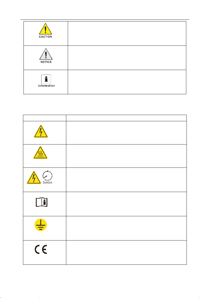
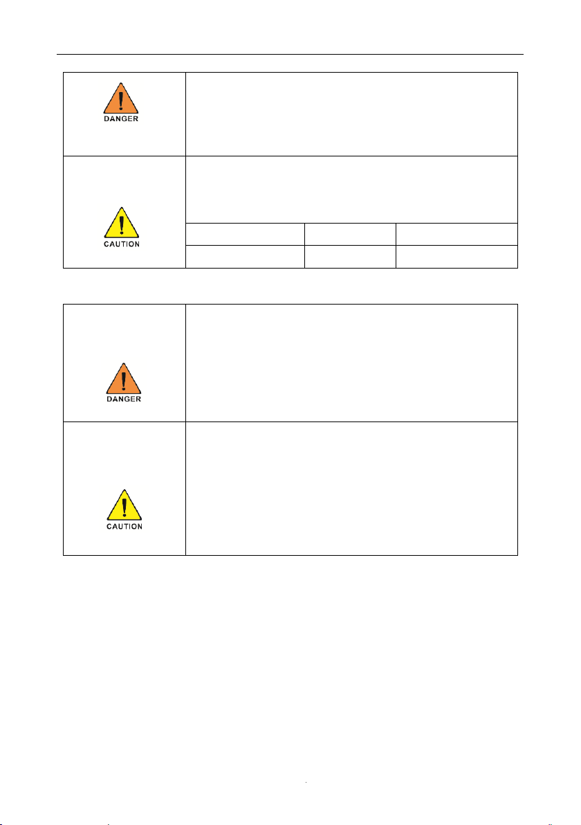
1.2 Symbols in this document
Please pay close attention to all the symbols for the purpose of avoiding possible personal injury
or equipment break down.
Symbol
description
DANGER indicates a hazardous situation which, if not avoided,
will result in death or severe injury.
WARNING indicates a hazardous situation which, if not
avoided, could result in death or severe injury.
User Manual
- 4 -
Markings on this product
CAUTION indicates a hazardous situation which, if not avoided,
could result in minor or moderate injury.
NOTICE is used to address practices not related to personal
injury
Information that you must read and know to ensure optimal
operation of the system.
Symbol
Explanation
Caution,risk of electric shock
Caution,hot surface
Operation after 5 minutes
Read the manual
Point of connection for grounding protection
CE mark.
The inverter complies with the requirements of the applicable CE
guidelines.
User Manual
- 5 -
2 Overview
2.1 Product Introduction
Function
HI-3/6K-SL series, also called hybrid or bidirectional solar inverters, apply to solar system with
participation of PV, battery, loads and grid system for energy management. The energy
produced by PV system shall be used to optimize self-consumption, excess power charge
battery and the rest power could be exported to the grid. Battery shall discharge to support loads
when PV power is insufficient to meet self-consumption. If battery power is not sufficient, the
system will take power from grid to support loads.
Models
This document involves the following product models:
HI-3K-SL,HI-3.6K-SL,HI-4K-SL,HI-4.6K-SL,HI-5K-SL,HI-6K-SL.
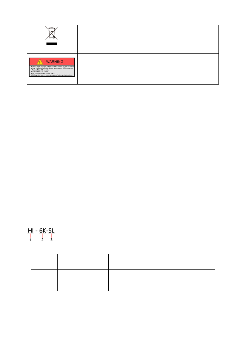
Model description (HI-6K-SL is used as an example)
Model description
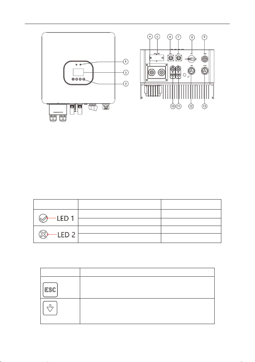
2.2 Appearance
The inverter must not be disposed of with the household waste.
Warning, high voltage.
Icon
Meaning
Description
1
Product
Hybrid inverter
2
Power level
6K :The rated power is 6 kW.
3
Topology
SL: Single phase low battery
SH: Single phase high battery
User Manual
- 6 -
① LED indicator ② LCD display ③ Function button ④ Communication port
⑤ GPRS/WIFI output port ⑥ Battery Terminals(+) ⑦ Battery Terminals(-)⑧DC switch
⑨ Grid Port ⑩ DC input terminals (PV1) ⑪DC input terminals (PV2) ⑫ GEN Port
⑬ Load Port
LED indicator description
Function button description
Category
Status
Meaning
Green light on
Normal status
Green light blinking
Alarm status
Red light on
Fault status
Blinking red at short intervals
Software updating
Category
Description
ESC button: Return from current interface or function.
Down button: Move cursor to downside or decrease value
User Manual
- 7 -
3 Installation
3.1 Check for Physical Damage
Make sure the inverter is intact during transportation. If there is any visible damage, such as
cracks, please contact your dealer immediately.
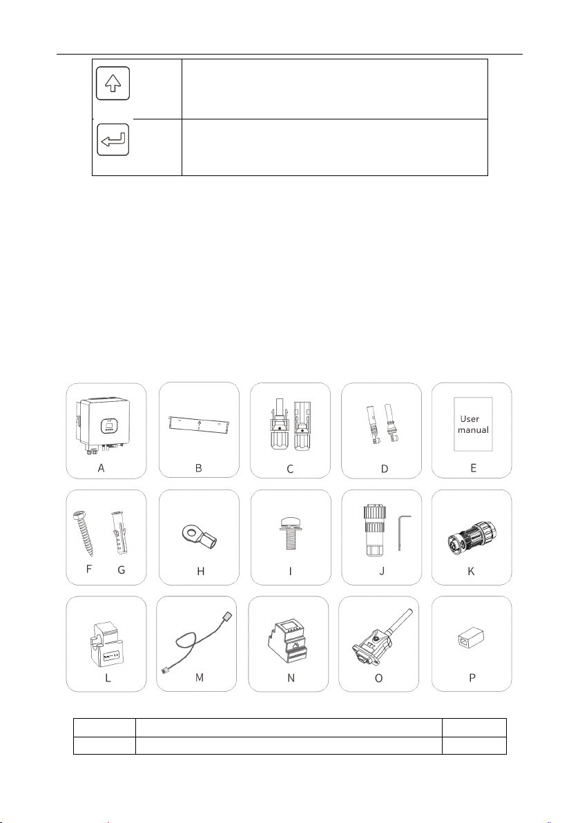
3.2 Packing List
Open the package and take out the product, please check the accessories first.
The packing list shown as below.
Up button: Move cursor to upside or increase value.
OK button: Confirm the selection.
Object
Description
Quantity
A
Inverter
1

User Manual
- 8 -
* P: When the length of CT wire cannot meet the use requirements, the CT communication wire
can be extended through RJ45 connector.
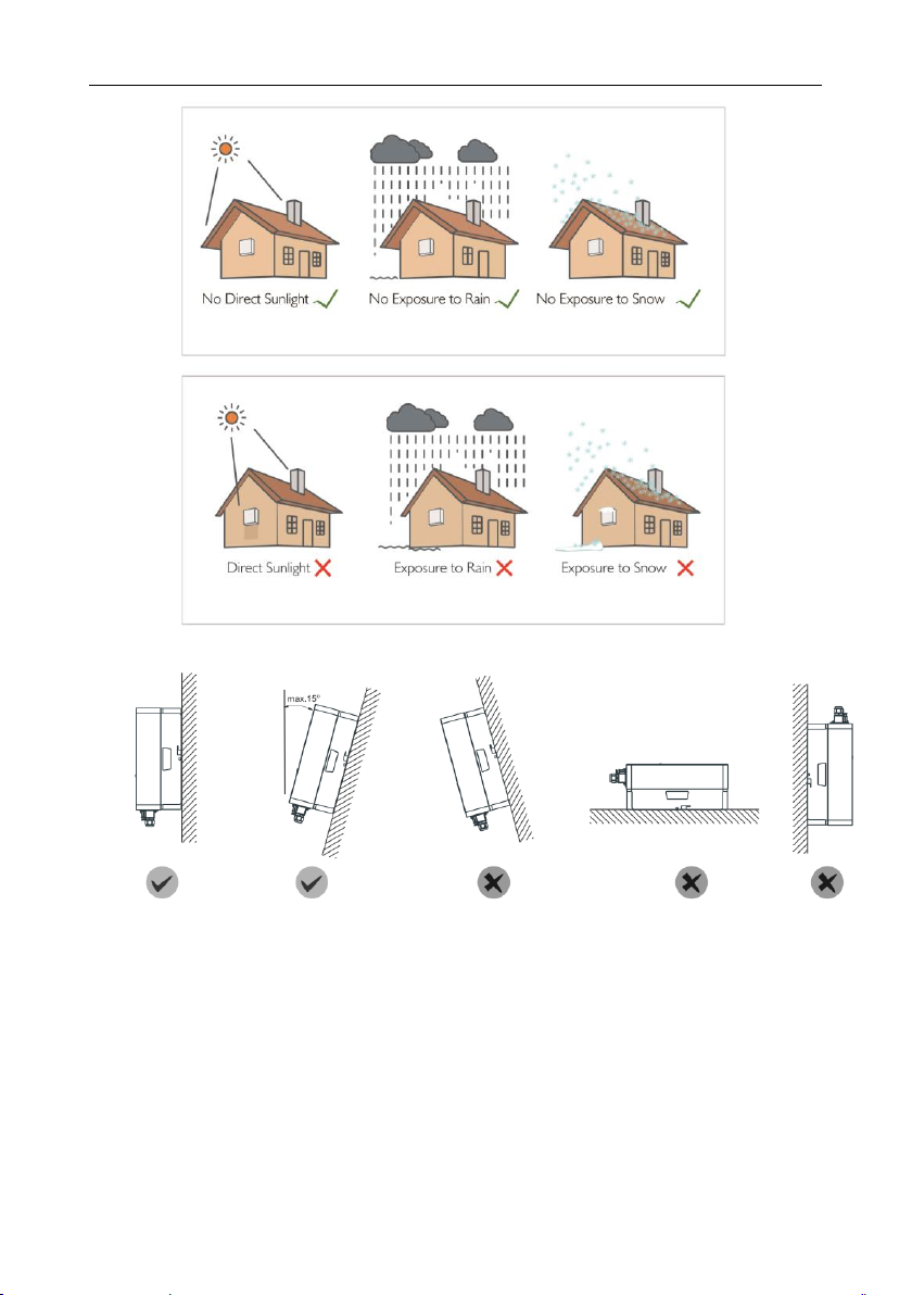
3.3 Mounting
Installation Precaution
HI-3/6K-SL series inverter is designed for outdoor installation (IP 65).
Make sure the installation site meets the following conditions:
◆ Not in direct sunlight.
◆ Not in areas where highly flammable materials are stored.
◆ Not in potential explosive areas.
◆ Not in the cool air directly.
◆ Not in environment of precipitation or humidity (>95%).
◆ Under good ventilation condition.
◆ The ambient temperature in the range of -20℃ to +60℃.
◆ The wall hanging the inverter should meet conditions below:
1.Solid brick/concrete, or strength equivalent mounting surface.
2.Inverter must be supported or strengthened if the wall’s strength is not enough (such as
wooden wall, the wall covered by thick layer of decoration).
Please avoid direct sunlight, rain exposure, snow laying up during.
B
Bracket
1
C
PV connectors (2*positive,2*negative)
2/2
D
PV pin connectors (2*positive, 2*negative)
2/2
E
User manual
1
F
Expansion tubes
3
G
Expansion screws
3
H
Ring terminal
1
I
Set screw (for mounting,external enclosure grounding)
2
J
grid output connector
1
K
Load/GEN connector
1
L
CT
1
M
Lead-acid battery temperature sensor
1
N
Meter (optional)
1
O
Wi-Fi module (optional)
1
*P
RJ45 connector
1
User Manual
- 9 -
◆ The slope of the wall should be within 15°.
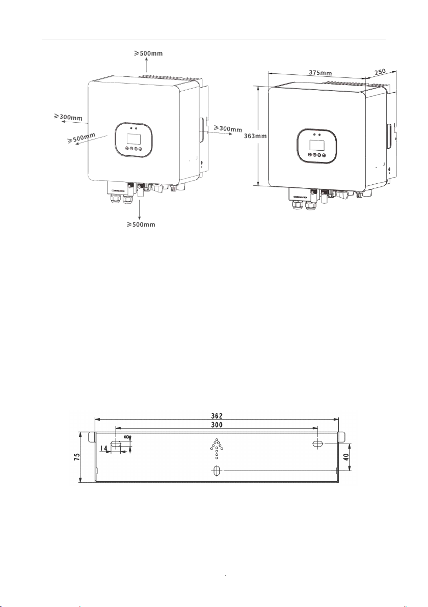
3.4 Space Requirement
User Manual
- 10 -
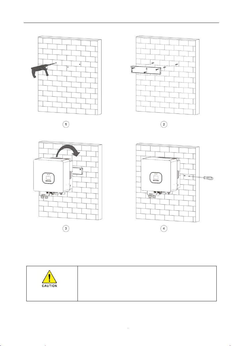
3.5 Mounting Steps
1.Use the wall bracket as a template to mark the position of the 3 holes on the wall(unit: mm).
2.Drill holes with driller, make sure the holes are deep enough (at least 60mm) for installation,
and then tighten the expansion tubes.
3. Install the expansion tubes in the holes and tighten them. Then install the wall bracket by
using the expansion screws. (Φ10 driller, torque: 2.5±0.2Nm)
4. Hang the inverter over the bracket, move the inverter close to it, slightly lay down the inverter,
and make sure the 2 mounting bars on the back are fixed well with the 2 grooves on the bracket.
5. After confirming the inverter is fixed reliably, fasten two M5 safety-lock sockets head cap
screws on the right or left side firmly to prevent the inverter from being lifted off the bracket
(torque: 2.0±0.2Nm).
User Manual
- 11 -
4 Electrical Connection
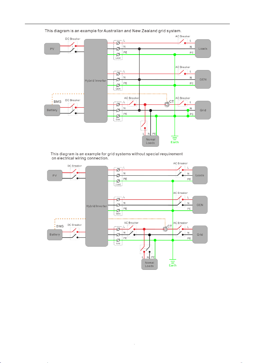
System connection diagrams
◆ For Australian safety country, the neutral cable of Grid side and Load
side must be connected together, otherwise Load function will not work.
User Manual
- 12 -
4.1 PV connection
◆ Conditions for DC Connection
The inverter has 2 independent inputs: PV1 & PV2 Notice that the connectors are in paired
(male and female connectors). The connectors for PV arrays and inverters are H4 connectors.
User Manual
- 13 -
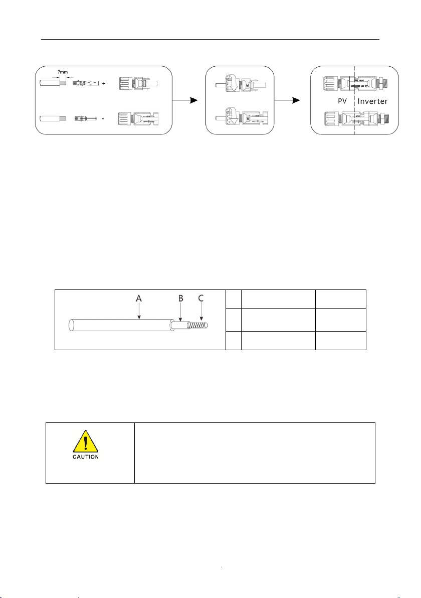
◆ Connecting the PV Array
Connection Steps:
1.Choose the 12 AWG wire to connect with the cold-pressed terminal.
2.Remove 7mm of insulation from the end of wire.
3.Insert the insulation into pin contact and use crimping plier to clamp it.
4.Insert pin contact through the cable nut to assemble into back of the male or female plug.
When you feel or heard a “click” sound the pin contact assembly is seated correctly.
The solar modules connected to the inverter must conform to the
Class A requirements of the IEC 61730 standard.
If the inverter is not equipped with a DC switch but this is mandatory in
the country of installation, install an external DC switch. The following limit
values at the DC input of the inverter must not be
exceeded:
Model
Max current PV1
Max current PV2
3K-6K
15A
15A
Danger to life due to lethal voltages!
◆ PV array supplies D.C voltage to inverter when exposed to light, before
connecting the PV array, cover some light screens above PV arrays,
ensure that the DC switch and AC breaker are disconnect from the
inverter. NEVER connect or disconnect the DC connectors under load.
◆ Make sure the maximum open circuit voltage (Voc) of each PV string is
less than the maximum input voltage of the inverter.
◆ Check the design of the PV plant. The Max. open circuit voltage, which
can occur at solar panels temperature of -10℃, must not exceed the Max.
input voltage of the inverter.
◆ Improper operation during the wiring process can cause fatal injury to
operator or unrecoverable damage to the inverter. Only qualified
personnel can perform the wiring work.
◆ Please do not connect PV array positive or negative pole to the
ground, it could cause serious damages to the inverter
◆ Check the connection cables of the PV modules for correct polarity and
make sure that the maximum input voltage of the inverter is not
exceeded
User Manual
- 14 -
5.Plug the PV connector into the corresponding PV connector on inverter.
4.2 Battery Connection
◆ Lead-Acid and other similar older-technology battery types require experienced and
precise design, installation, and maintenance to work effectively. For lead-acid battery bank,
the inconformity between battery cells might lead to battery cell over-charge or discharge, and
further might damage battery cells and shorten battery bank life.
◆ For lithium battery (pack) the capacity should be 50Ah or larger. Battery cable requirement
as below.
Table 1 Cable recommended.
◆ Please be careful against any electric shock or chemical hazard.
◆ Make sure there is an external DC switch (≥125A) connected for battery without build-in
DC switch.
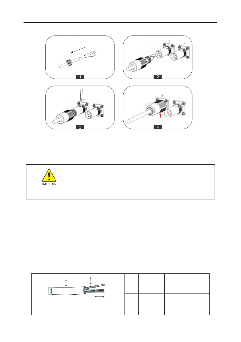
Battery wiring connection steps as below:
1. Prepare battery cables and accessories and put battery power cable through battery cover.
Compress the terminal head by using a crimping pliers.
2.Connect battery terminals onto inverter.
3.Tighten screws.
A
O.D
10-12mm
B
Isolation section
NA
C
Area
20-25mm²
◆ Make sure battery switch is off and battery nominal voltage meet
specification before connecting battery to inverter and make sure inverter
is totally isolated from PV and AC power.
◆Please make sure polarity (+/-) of battery are not reversed.
User Manual
- 15 -
4. Tighten the screw cap.
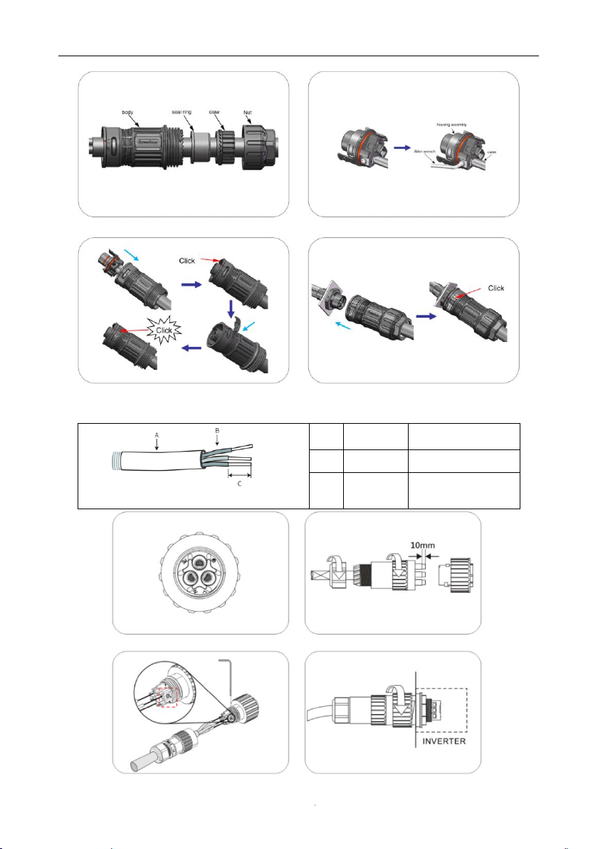
4.3 Grid & GEN & Backup Connection
An external AC switch is needed for grid connection to isolate from grid when necessary.
Connection Steps
1. Choose the appropriate wire, Wire Stripping(Cable size: refer to Table).
2.Set the parts on the cable one by one.
3.Wire crimping cord end terminal can be inserted into the housing quickly according to the
sign.
4.Insert Seal and Clamp Finger into socket, then tighten the nut.
Grid Connection:
◆ Make sure inverter is totally isolated from any DC or AC power before
connecting AC cable.
A
Diameter
13-18mm
B
Area
10mm²or 8AWG
C
Length
11mm
User Manual
- 16 -
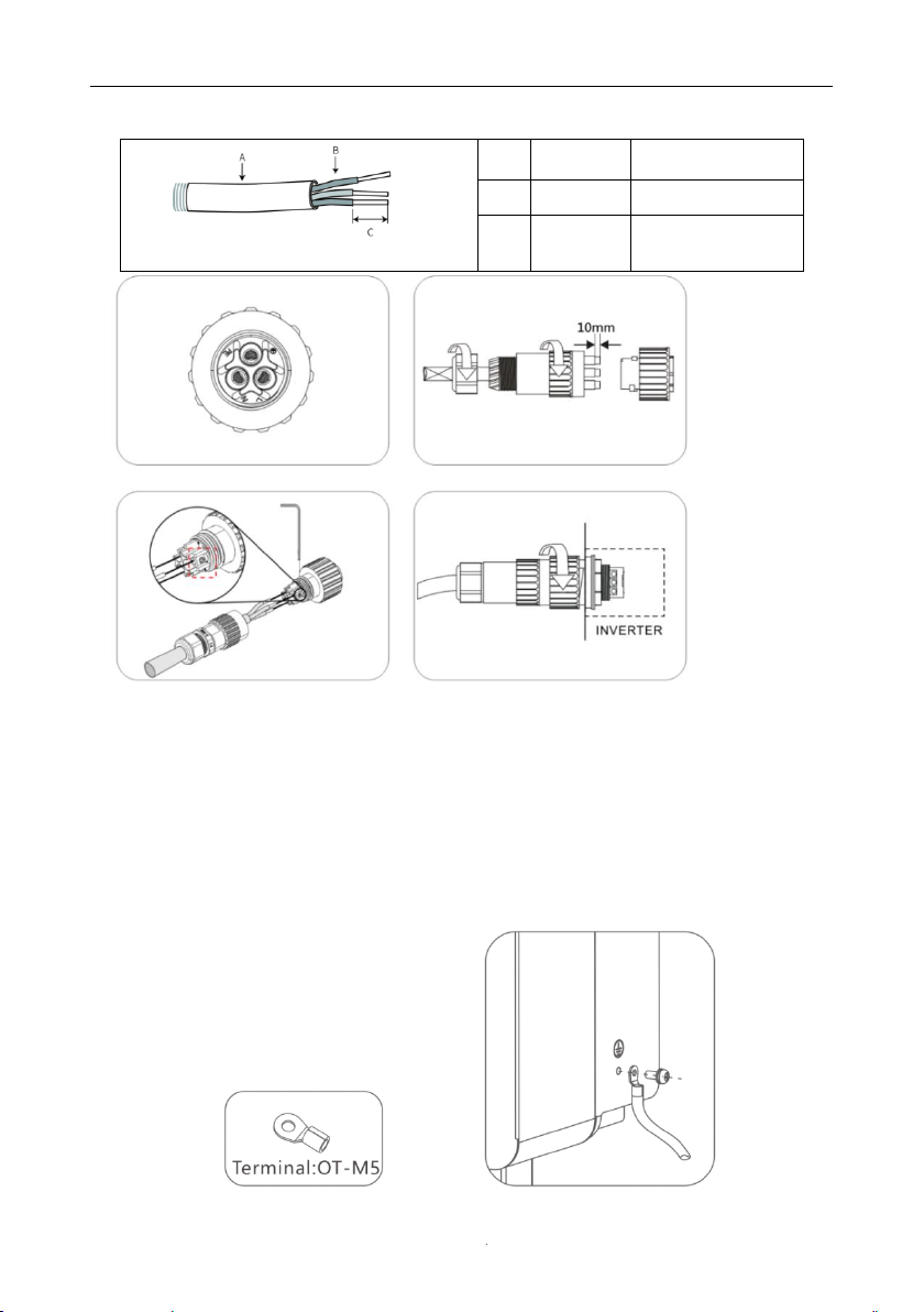
Load Connection
A
Diameter
10-14mm
B
Area
6mm²or 10AWG
C
Length
10mm
User Manual
- 17 -
GEN Connection
4.4 Earth Connection
Users must additionally earth the inverter to the enclosure of a second earthing or
equipotential bonding. This prevents electric shock if the original protective conductor fails.
Earth Connection Steps:
1. Strip the earthing cable insulation and insert the stripped cable into the ring terminal, then
clamp it.
2. Place the ring terminal into the earthing rod and screw the earthing screw tightly.
A
Diameter
10-14mm
B
Area
6mm²or 10AWG
C
Length
10mm
User Manual
- 18 -
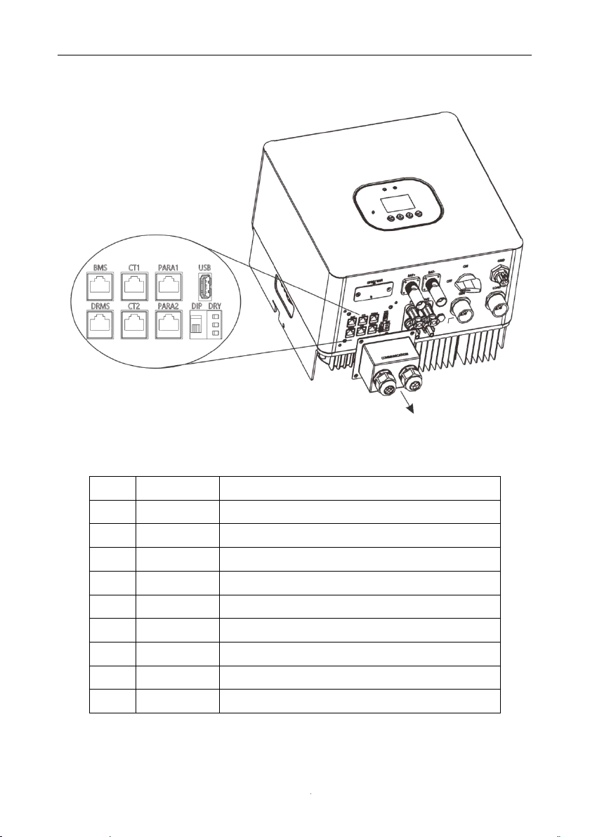
4.5 Communication Connection
1.Function port definition
Object
Category
Description
1
BMS
RS485/CAN/NTC port for battery communication
2
DRMS
For Australia market only
3
CT1
Current transformer port1/ Meter communication port
4
CT2
Reserve
5
PARA1
Reserve
6
PARA2
Reserve
7
USB
Upgrade firmware program port
8
DRY
External devices communication port
9
DIP
DIP Switch
User Manual
- 19 -
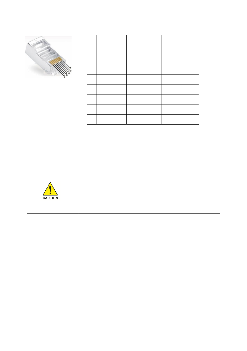
◆ Make sure use standard RJ45 cable and plug, as below
2.CT1 Connection
◆ The CT in product box is compulsory for inverter system installation, used to detect grid
voltage and current direction and magnitude, further to instruct the operation condition of
inverter via RS485 communication.
CT Connection Diagram:
Pin
BMS
CT1
DRMS
1
RS485B
CT1_RS485B
DRM1/5
2
RS485A
CT1_N
DRM2/6
3
GND-S
CT1_N
DRM3/7
4
CANH
GND-S
DRM4/8
5
CANL
CT1_RS485A
DRM_REF
6
NTC.BAT
CT1_P
DRM_COM
7
Wake-
CT1_P
RS485A
8
Wake+
CT1_ON+
RS485B
◆ Make sure inverter is totally isolated from any DC or AC power before
connecting AC cable.
◆Direction of the CT cannot be connected in reverse, please follow
“K→L” direction to do the connection. Make sure CT are connected
between loads and grid.
Other manuals for HI-3K-SL
1
This manual suits for next models
5
Table of contents
Other INHENERGY Inverter manuals


