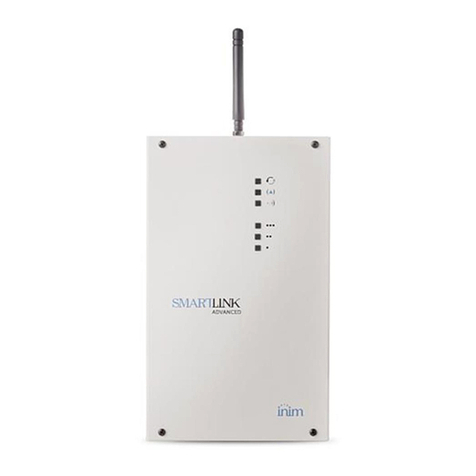
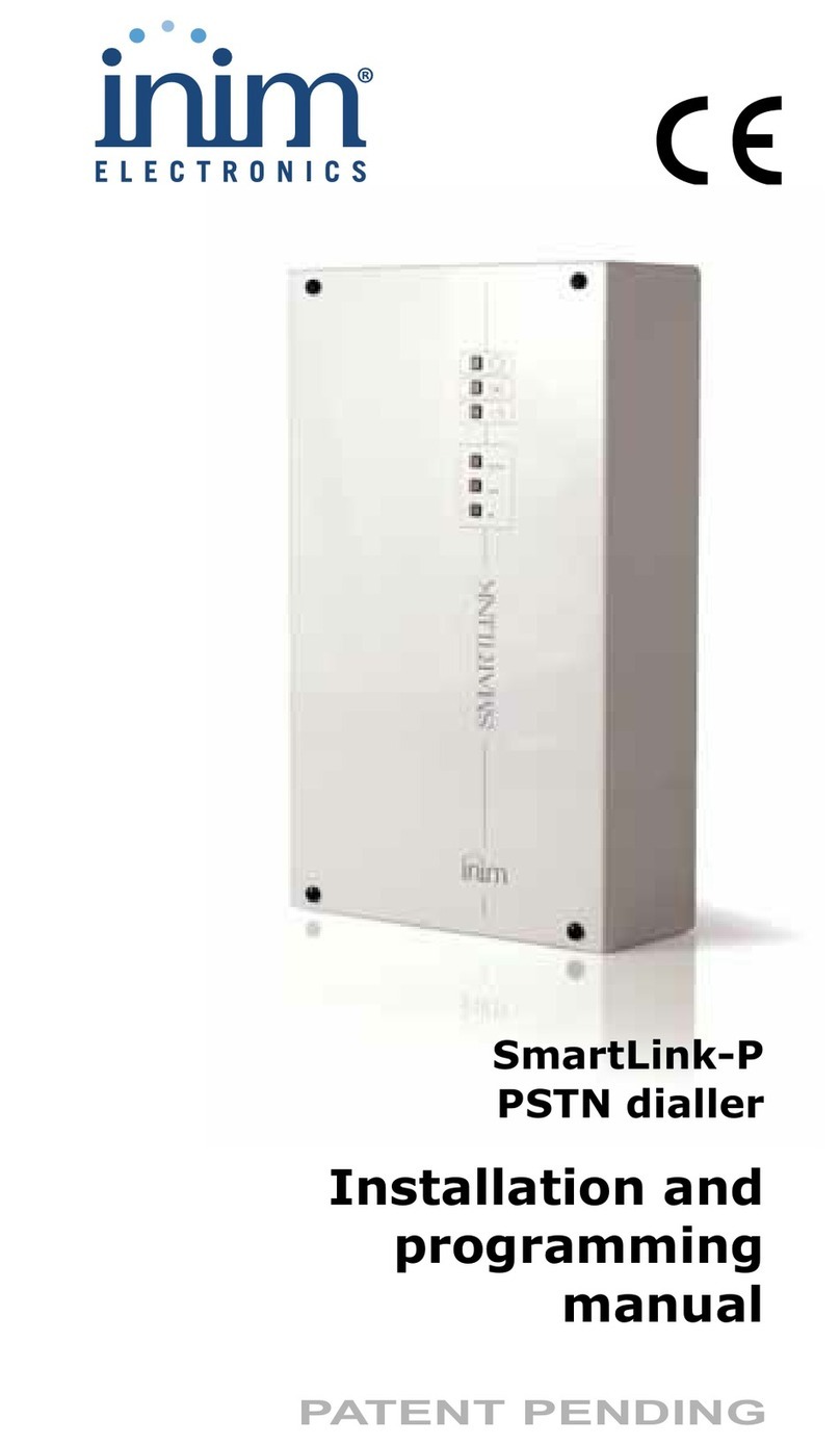
INIM Electronics SmartLink-G User manual

SmartLink-G, SmartLink-GP
GSM Dialler
Installation
Manual
PATENT PENDING
0470

Installation manual
2
Copyright
The information contained in this document is the sole
property of INIM Electronics s.r.l. No part may be copied
without written authorization from INIM Electronics s.r.l.
All rights reserved.
Directive 1999/5/CE (R&TTE) compliance.
Hereby INIM Electronics s.r.l. declares that the
SmartLink-G and SmartLink-GP are in compliance with
the essential requirements and other relevant provisions
of Directive 1999/5/CE.
The full declarations of conformity of the above-
mentioned devices are available at URL:
www.inim.biz/dc.html.

3
Installation manual
Table of contents
Chapter 1 Introduction .................................5
1.1 Application and use 6
1.2 Other applications 7
Chapter 2 General information....................... 9
2.1 Documentation supplied 9
2.2 Manual 9
2.3 Addresses 9
2.4 Software information 9
2.5 Intellectual property rights 9
2.6 Key 10
2.7 Manufacturer's name and address 10
2.8 Device identifier 11
2.9 Warranty 11
2.10 Safety laws 11
Chapter 3 Device management.................... 13
3.1 Shipping 13
3.2 Environmental conditions 13
3.3 Unpacking the device 13
Chapter 4 Technical description ................... 15
4.1 Technical specifications 16
4.2 Reserve line electrical specifications 16
Chapter 5 Internal devices .......................... 17
5.1 Terminal board 17
5.2 Status LEDs 20
Chapter 6 Device features........................... 22
6.1 Intrusion control 23
6.2 Digital dialler (Contact ID) 23
6.3 SMS dialler 23
6.4 Voice dialler 23
6.5 Remote activation via SMS text message 23
6.6 Remote control via DTMF 24
6.7 Caller ID 24
Chapter 7 Installing the SmartLink-GP.......... 25
7.1 Wall mounting 25
7.2 Mounting the antenna 26
7.3 Mounting the remote antenna 27
7.4 Connecting the land line (PSTN) 28

4
Installation manual
7.5 Connecting telephone devices 28
7.6 Earth connection 28
7.7 Connecting the tamper microswitch 28
7.8 Connecting the IN&OUT terminals 28
7.9 Connecting the SmartLogos60 (accessory
item) 29
7.10 Inserting the SIM card 29
7.11 Connecting the DC power 29
7.12 Connecting an ancillary power supply 30
7.13 Connecting the RS232 PC serial link 30
7.14 DC power 32
7.15 Closing the casing 32
7.16 Initializing phase 32
7.17 Test 32
Appendix A Features not managed by the Smart-
Link-G model ..............................33
Appendix B Order code .................................34

Introduction 5
Installation Manual
Chapter 1
Introduction
SmartLink is available in the following models:
• SmartLink-GP
•SmartLink-G
Besides the features of the SmartLink-G model, the SmartLink-GP model
also provides the following advanced features:
1. intrusion control
2. voice dialler (requires SmartLogos60 accessory board)
3. PSTN line call management
The Smartlink-G model does not manage these features.
This manual describes the Smartlink-GP features and programming process.
SmartLink-G users can skip the sections which refer to the advanced
features.
Refer to Appendix A for a detailed list of the extra features provided by
Smartlink-GP and respective programming process.

6Introduction
Installation Manual
1.1 Application and use
The SmartLink-GP device described in this manual is a reserve telephone line
generator.
Figure 1 - Reserve telephone line
In the event of land line trouble (PSTN line down) the Smartlink-GP will
switch all calls to the GSM network (simulated-line mode). This operating
mode will not affect any of the connected devices. During simulated-line
mode, the SmartLink-GP will check the land-line for restoral at regular
intervals. If the land line restores during GSM line-free status, the system
will switch back to the land line. Otherwise it will switch back when the
ongoing call ends.
GSM network

Introduction 7
Installation Manual
The Smartlink-GP provides a series of optional features, some of which
require accessory boards:
• Intrusion control
• Operations manager (e.g. sends calls, output commands) generated by
internal events (e.g. low battery) or external events (e.g. input status
changes, received calls, received SMS text messages)
• Output status enquiry and commands via SMS
• Output status enquiry and commands via DTMF
• Caller ID Output commands
• Digital dialler (Contact ID)
• SMS dialler
• Voice dialler (optional feature)
1.2 Other applications
The diagrams on the following pages illustrate some of the vast range of
SmartLink-GP applications.
Figure 2 - Output status enquiry and commands via DTMF
and SMS text messages — PSTN (land line) or GSM network

8Introduction
Installation Manual
Figure 3 - Intrusion panel feature - digital telephone dialler
(Contact ID) - land line (PSTN) and GSM network
Figure 4 - Operations manager in response to external events
- SMS dialler- Voice dialler (optional feature)
GSM network GSM network
Detector
Voice message
GSM
network

General information 9
Installation Manual
Chapter 2
General information
2.1 Documentation supplied
• Installation manual (this manual)
• Programming manual
If you require the Programming manual, please contact INIM Electronics
s.r.l. and specify the order code shown in Appendix B .
2.2 Manual
Title: SmartLink-G and Smartlink-GP Installation Manual
• Edition, Issue: 2.10
• Month and Year of issue: October 2012
• Order code: DCMIINE0SLINK
2.3 Addresses
• Installer
• Technical assistance
2.4 Software information
• Smartleague software version: 3.x.x
• Firmware version : 2.x.x
2.5 Intellectual property rights
The information contained in this document is private property. All rights
reserved.
No part of this document may be copied or reproduced unless expressly
authorized in writing by INIM Electronics, in particular the parts regarding
the device specified in 2.8 Device identifier.
INIM Electronics s.r.l. shall not be responsible for damage arising from
improper application or use.

10 General information
Installation Manual
2.6 Key
2.6.1 Glossary and terminology
Device: refers to the device defined in 2.8 Device identifier.
Left, right, behind, above, below: indications using the operator’s position
in front of the mounted device as the reference point.
Pulse output: same as "monostable output".
Dialler (telephone, SMS, digital):same as "communicator".
Qualified personnel: those persons whose training, expertise and
knowledge of the respective laws and bylaws regarding service conditions
and the prevention of accidents, are able to identify and avoid all possible
situations of danger.
2.6.2 Graphic conventions
Text in italics: indicates the title of a chapter, section, paragraph, table or
figure in this manual or other published reference.
[Uppercase letters] (e.g.[A]): indicate the device parts.
Note: The detached notes contain important information relating
to the respective text.
Attention: The attention prompts indicate that total or partial
disregard of the procedure could damage the
connected devices.
Danger: The danger warnings indicate that total or partial
disregard of the procedure could injure the operator
or persons in the vicinity.
2.7 Manufacturer's name and address
INIM Electronics s.r.l.
Via Fosso Antico, Centobuchi
63033 Monteprandone (AP) - Italy
Tel: +39 0735 70 50 07
Fax: +39 0735 70 49 12

General information 11
Installation Manual
2.8 Device identifier
Figure 5 - Overview
Product class: GSM dialler
Model: SmartLink-GP
Year of manufacture: 2012
2.9 Warranty
INIM Electronics s.r.l. warrants the original purchaser that for a period of 24
months from the date of production, the product shall be free of defects in
materials and workmanship. The warranty applies only to defects in parts
and workmanship relating to normal use. It does not cover:
• Improper use or negligence
• Damage caused by fire, flood, wind, or lightning
• Vandalism
• Fair wear and tear
Inim Electronics s.r.l. shall, at its option, repair or replace any defective
products. Improper use, that is, use for purposes other than those
mentioned in this manual will void the warranty. For the full details and
conditions regarding the warranty, refer to the purchase order.
2.10 Safety laws
The aim of the instructions in this section is to ensure that the device is
installed and handled properly. This chapter contains vital information. The
installer should be familiar with this section and bring each item to the
attention of the system users.

12 General information
Installation Manual
2.10.1 Managing electronic devices
The normal motions of any person may generate electrostatic potential of
thousands of volts. Discharge of this current through semiconductor devices
during handling may cause serious damage which although may not be
immediately evident may reduce the reliability of the circuits.
If located in their housings, the electronic circuits of INIM Electronics
products are highly immune to electrostatic discharge.
Do not expose the circuits to damage by removing the modules unnecessarily
from their housings.
1. When removing or handling the boards, hold the board edges only.
2. Do not touch the electronic components, the printed circuits or the metal
parts of the connectors.
3. Up to 100Vdc may be applied to terminals 13 and 14 during the ring phase.
4. Do not hand the module to another person without first ensuring that
you both have the same electrostatic potential. This can be obtained by
simply shaking hands.
5. Place the module on an anti-static surface or a conductor surface with
the same potential.
Further information regarding procedures relating to safety when working
with electronic devices can be found in normative IEC 60147-0F.
2.10.2 Setting up the system
In order to provide adequate protection and instructions for proper use,
security professionals (Installers and maintenance/test technicians) must be
familiar with the operating procedure of this device.
Please read the instructions carefully before installing and/or servicing the
system.
Before first power-up, be sure that the earth connection has been completed
properly on the respective terminal.
The recommended minimum wire cross section for the earth connection is
2.5 mm2, that is, unless expressly stated in the respective documentation.
2.10.3 Replacement and disposal of used devices
Replacement
When replacing used devices, disconnect the devices concerned then
complete the connections of the replacement devices in compliance with the
instructions printed on the respective inserts.
Contact your local municipal offices for information regarding the disposal of
used electronic devices.
Disposal
Do not burn used electronic devices, or allow them to pollute the
environment (countryside, rivers, etc.). Electronic devices must be disposed
of in a safe environment-friendly way. In order to avoid short-circuits, take all
the necessary precautions when removing used batteries. Contact your local
municipal offices for information regarding the disposal of batteries.

Device management 13
Installation Manual
Chapter 3
Device management
3.1 Shipping
Once the device has been properly packed and put into cartons, care must
be taken to avoid accidental damage during transport. The cartons should be
placed in such a way as to avoid knocks and falls, and special care must be
taken to protect the devices from extreme heat and/or cold.
3.2 Environmental conditions
Temperature limits
-10° / +55°C for transport and storage
+5° / +40°C operating temperature
3.3 Unpacking the device
The device is packed in a side-opening cardboard and must be unpacked
with care. All waste packaging materials must be disposed of in compliance
with the local laws and bylaws in force.
Note: The package does not include: 1.2 A/h Battery, or SIM
card. Be sure to have these items on hand before starting.
Inside the box:
• SmartLink-GP PCB mounted on one metal and three plastic supports
• The plastic box (inside) contains:
- 1 Antenna
- 10 resistors @ 15kohm
- 4 frontplate screws

14 Device management
Installation Manual
Figure 6 - SmartLink-GP PCB with antenna
The following accessory items must be ordered separately (see Appendix B
for the order codes):
• SmartLogos60 voice board (see Figure 16 - Connecting the
SmartLogos60).
• DC power supply
• SmartLink-REM-ANT remote indoor antenna
Figure 7 - SmartLogos60 voice board, power supply,
SmartLink-REM-ANT remote indoor antenna (the components
in the figure are not in real size)

Technical description 15
Installation Manual
Chapter 4
Technical description
Figure 8 - SmartLink-GP PCB
Main components
Chapter 5 - Internal devices provides an in-detail description of the main
components.
[A] Terminal board
[B] LEDs
[C] RS232 serial port connector
[D] Buzzer
[E] Antenna connector
[F] Microchip with firmware version label
[G] Tamper microswitch
[H] SmartLogos 60 voice board connector
[I] SIM card holder
C
D
E
F
H
I
A
B
G

16 Technical description
Installation Manual
Note: INIM s.r.l. reserves the right to change, replace, in part or
entirely, the components not strictly relating to use and
which, do not involve the installation process described in
Chapter 7 - Installing the SmartLink-GP.
4.1 Technical specifications
4.2 Reserve line electrical specifications
DC power 13.8 Vdc ±10%
PCB operating current draw 100 mA in standby, 300 mA during
transmission, 600 mA maximum
Maximum current draw on
terminal +AUX
400mA
Maximum battery-charge
current
400mA
Battery specifications 12V 1, 2Ah
GSM band frequence 900 and 1800 Mhz (Dual band)
Outputs Maximum 5
open-collectors @ 150 mA
Inputs Maximum 5, with 3 programmable
thresholds
Dimensions (W x H x D)
without Antenna
134 x 220 x 53 mm
Weight (without battery) 890g
Current 40Vdc
Loop current 25mA
Dialling tone Continuous @ 425Hz
Engaged tone 200ms 425Hz -
200ms silence
Recognised dialling tone DTMF
Ring voltage 100Vpp

Internal devices 17
Installation Manual
Chapter 5
Internal devices
5.1 Terminal board
Figure 9 - Terminal board
Nr. Identifier Description Notes
1 +PWR Positive power
terminal
2 -PWR Negative power
terminal
3 +AUX Ancillary 12Vdc
400mA
4 Ground:
reference for signals
on terminals; DC
power negative
5 IO1 Input/Output
terminals
13.8Vdc
150mA sink each
terminal
6IO2
7IO3
8IO4
9IO5

18 Internal devices
Installation Manual
Attention: The device that supplies power to terminals 1 and 2
must be overvoltage and short-circuit protected.
Note: A custom power supply to terminals 1 and 2 is available on
request. Order code: IPS12015DT. Devices with same
voltage and current specifications can also be used.
5.1.1 Line-down management
The devices which are to access the reserved line during line-down status
must be connected to terminals 13 and 14.
During normal operating conditions, terminals 13 and 14 are connected to
the land line terminals 15 and 16. If the voltage drops below 3Vdc for over
10 seconds, the SmartLink-GP will switch from the land line (PSTN) to the
reserve line. After 3 minutes, the SmartLink-GP will check the status of the
land line.
“Enable PSTN Down Warning”
PSTN line-down events will be signalled by four blinks on the Fault LED (red
LED). Signalling will not start until the line- down condition has been present
for 3 minutes.
10 OPEN Tamper microswitch
[G] terminals — see
Figure 8 -
SmartLink-GP PCB.
13.8Vdc
100mA
11
12 To be connected to
the mains earth.
13 To be connected to
devices which access
the telephone line
(e.g. telephone
devices, control
panels, etc.).
up to 4 telephone
devices connected
in parallel
14
15 PSTN Land line (PSTN)
connection
16
Nr. Identifier Description Notes

Internal devices 19
Installation Manual
5.1.2 IN&OUT Input/Output terminals
Terminals 5 to 9 can be configured as input terminals or output terminals or
both.1
Note: For details regarding the configuration of the terminals,
refer to the Programming manual.
Terminals used as inputs
Three threshold values can be applied thus each input can be associated with
four statuses. During status transition, SmartLink-GP can perform the
following operations:
• Send an SMS text message
• Transmit a Contact ID report
• Send a voice message (optional feature)
• Command an output
• Perform operations and commands
Terminals used as outputs
The outputs operate as open-collector outputs and allow external device
management (e.g. lights ON, Open gate, etc.). On output activation
SmartLink-GP can:
• Send an SMS text message, a feedback ring or both
• Activate an external buzzer
• Attivate an external LED
The standby conditions of the outputs can be:
•Open
• Closed
The outputs can be configured as:
•Bistable
•Pulse
An output can be activated by:
• an event
• an SMS text message
•aDTMFcall
• an incoming call using CallerID
Example of Input configuration and terminal statuses
If SmartLink-GP is used as a intrusion control panel, the statuses of "DEOL"
inputs will be as follows:
1. Wire-cut tamper
2. Alarm
3. Standby (normal condition)
4. Short-circuit tamper
1. Patent pending

20 Internal devices
Installation Manual
During the transition from one status to another, it is possible to activate one
of the following actions:
• send an SMS text message
• call a Central Station
• send a recorded message
• activate an alarm sounder
•etc.
5.2 Status LEDs
The SmartLink-GP board provides six status LEDs, with the following
meaning.
Figure 10 - LED
LED Colour Indicates Status
1 Green Operating
status
- ON: device in service
- Blinking: device initializing
2 Red Trouble Blink pause sequence:
- 1 blink: low battery
- 2 blinks: SIM card trouble
- 3 blinks: communication trouble
with the GSM unit
- 4 blinks: land line down
- 5 blinks: line engaged during
initializing phase
2
3
4
5
6
1
Other manuals for SmartLink-G
1
This manual suits for next models
1
Table of contents
Other INIM Electronics Conference System manuals
Popular Conference System manuals by other brands

COMMUNICATIONS-APPLIED TECHNOLOGY
COMMUNICATIONS-APPLIED TECHNOLOGY ICRI-WFM Setup and operating procedures

TrueConf
TrueConf TrueConf Server Administrator's guide

Vokkero
Vokkero SQUADRA VARSITY manual

Seneca
Seneca R-COMM installation manual

Polycom
Polycom SIP 3.0.2 Administrator's guide

PEIKER CEE
PEIKER CEE CEECOACH PLUS instructions