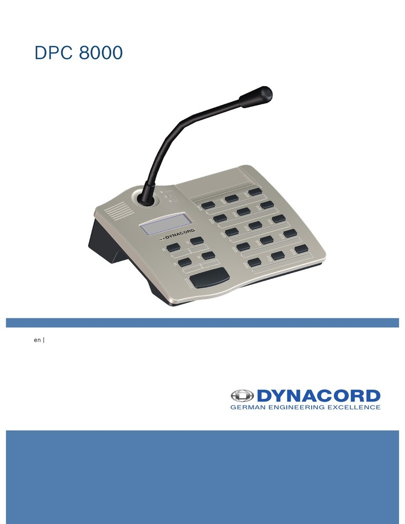
Dynacord PMX-CSK User manual

PMX-CSK
PROMATRIX
8000
CALL STATION KIT
Owner‘s Ma
nual

C
ALL
S
TATION KIT
INTRODUCTION
System
overview
Scope
of Delivery
and
Warranty
DESCRIPTION
Main features
Top view
Connection tables
Selection tables
Default functions & indications
Factory presets
Block diagram
Connections
OPERATION
LC-display
Operation
mode
Call
station kit mode configuration
User menu
Setup menu
APPENDIX
CAN Bus
principles
PMX-CSK interfaces
DPC 8120 CALL STATION EXTENSION
Technical data
Main data
Accessories
Standards

IMPORTANT SAFETY
INSTRUCTIONS
The lightning flash with arrowhead symbol, within an equilateral
triangle is intended to alert the user to the presence of
uninsulated „dangerous voltage“ within the product’s
enclosure that may be of sufficient magnitude to constitute a
risk of electric shock to persons.
The exclamation point within an equilateral triangle is intended
to alert the user to the presence of important operating and
maintenance (servicing) instructions in the literature
accompanying the appliance.
1.
Read these
instructions.
2.
Keep these
instructions.
3.
Heed all
warnings.
4.
Follow all
instructions.
5.
Do not use this apparatus near
water.
6.
Clean only with
a
dry
cloth.
7. Do not cover any
ventilation openings.
Install in
accordance
with the manufactures
instructions.
8. Do not install near heat
sources
such as
radiators,
heat
registers, stoves,
or other
apparatus (including amplifiers) that produce
heat.
9.
Do not defeat the safety purpose of the polarized or the grounding-type plug.
A polarized
plug has two blades with one wider than the other. A grounding type plug has two
blades
and a third
grounding prong.
The
wide blade
or the third
prong
are
provided
for your
safety. I the
provided plug
does not fit into your outlet, consult an
electrician for
replacement of the obsolete
outlet.
10. Protect the power cord from being walked on or pinched
particularly at
plugs,
convenience receptacles, and the point where they exit from the apparatus.
11.
Only use attachments/accessories specified by the
manufacturer.
12. Use only with the cart, tripod, bracket, or table specified by the
manufacturer,
or sold with the
apparatus.
When a cart is used, use
caution when moving the cart/apparatus combination
to
avoid injury
from
tip-over.
13.
Unplug this apparatus during lightning storms
or
when unused
for a long
period of
time.

14. Refer all servicing to qualified service
personnel. Servicing
is required when the
apparatus
has been
damaged
in any way, such as
power-supply
cord or plug is
damaged,
liquid has been spilled or objects have fallen into the
apparatus,
the
apparatus
has been
exposed
to rain or
moisture,
does not
operate normally,
or has
been
dropped.
15.
Do not expose this equipment
to
dripping
or
splashing and ensure that no objects
filled
with liquids, such as vases, are placed on the
equipment.
16. To
completely disconnect
this
equipment
from the AC
Mains, disconnect
the power
supply cord plug from the AC
receptacle.
17.
The mains plug
of
the power supply cord shall remain readily
operable.
IMPORTANT SERVICE
INSTRUCTIONS
CAUTION: These servicing instructions are for use by qualified personnel
only.
To
reduce the risk
of
electric shock, do not perform any servicing
other
than that
contained in
the
Operating Instructions
unless you are
qualified to do so. Refer all servicing to qualified service
personnel.
1.
Security regulations as stated in the EN 60065 (VDE 0860
/
IEC 65) and the CSA E65
-
94 have
to be obeyed when servicing the
appliance.
2. Use of a mains
separator transformer is
mandatory during
maintenance while
the
appliance
is
opened, needs to be operated and
is
connected to the
mains.
3.
Switch
off the
power before retrofitting
any
extensions, changing
the
mains voltage
or
the
output
voltage.
4.
The minimum distance between parts carrying mains voltage and any accessible
metal
piece
(metal enclosure), respectively between
the
mains poles
has to be 3 mm and
needs
to be
minded
at all
times. The minimum distance between parts carrying
mains
voltage and any
switches
or
breakers that are
not
connected
to the
mains (secondary parts) has to be
6
mm
and needs to be minded
at
all
times.
5.
Replacing special components that are marked
in
the circuit diagram using the
security
symbol
(Note)
is
only permissible when using original
parts.
6.
Altering the circuitry without prior consent or advice
is
not
legitimate.
7.
Any work security regulations that are applicable at the locations where the appliance
is
being
serviced have to be strictly obeyed. This applies also to any regulations about
the
work place
itself.
8.
All instructions concerning the handling
of
MOS-circuits have to be
observed.
NOTE: SAFETY COMPONENT (MUST BE REPLACED
BY ORIGINAL PART)
WEEE RECYCLING/DISPOSAL
INSTRUCTIONS
The Wheelie Bin symbol found on the product or in the manual indicates that
this product must not be disposed of with other waste. It is in our category the
manufacturer’s responsibilityto properly dispose of their waste electrical and
electronic equipment (WEEE) at the end of its life. Due to the differences in
each EU country’s management of WEEE, please contact your local
distributor. We are committed to facilitate our own
electronic-waste-
management-system,
for the free of charge return of all EVI Audio GmbH
products: Telex, DYNACORD, Electro-Voice and RTS. Arrangements are
made with the dealer where you purchased the equipment from, for the
returning of all unusable equipment at no cost, to the factory in Straubing, for
environmental protective disposa

1.
Intr
oduction
1.1
Sy
s
t
em
o
v
er
v
i
e
w
The PMX-CSK Call Station Kit contains a printed circuit board (PCB) that can be
used to make custom-made call stations (e.g. a fireman’s panel) and belongs to
the PROMATRIX 8000 product family.
PMX-CSK is the kit version of the DPC 8015 with some small kit spec
differentiations. Eg, the PMX-CSK provides a connection to the
go
o
s
e
neck
microphone as known from the call station DPC 8015 but also provides a
connection to connect to a Dynamic EMERGENCY microphone like the
BOSCH LBB 9081. It provides
15
programmable contact closures
and 5
p
r
ep
ro
gramm
e
d contact closures for eventual menu access
. Up to 3 alarm
keys or key-locked switches can be
connected
.
The PMX-CSK employs a
lighted LC-display (122 x 32
p
i
xel).
The call station includes the
following
f
e
at
ure
s
:
•
condenser or dynamic microphone with pre-amplifier and compressor
/
limiter
circuitry
•
freely programmable k
ey-
as
signment
•
additional alarm keys or key-locked switches can be connected
•
connection of an
external
PTT-microphone or audio so
ur
ce
•
l
o
u
d
s
p
e
a
k
e
r connection
•
high resolution
L
C
-disp
l
a
y
•
user menu allows additional parameter settings at the call
station kit
•
microphone and line sur
ve
i
ll
ance
•
error indication via LED connections, loudspeaker and
text
messages
at
L
C
-d
i
s
play
•
all functions are
pr
ocesso
r
-
con
t
r
o
ll
ed
•
processor surveillance via watchdog
f
u
nc
ti
on
•
configuration data is stored in non-volatile
FLASH
RA
M
The call station kit is
processor-controlled
and extensive
monitoring
functio
n
s are
provided.
The
watchdog function monitors
the processor
system.
T
h
e line surveillance
function
recognizes any
line-interruption
and/or
sh
ort-circuits
in
t
h
e audio and CAN cabling. The
microphone
surveillance and the PTT button surveillance checks
functionality
and
recognizes any
interruption and/or
s
h
ort-
ci
rc
uit.
The
IRISNe
t
software
allows
comfortably configuring
t
h
e call
sta
t
io
ns kit.
Its
graphic,
dialogue-oriented
user
interface
offers
effortless
assign of key
func
tions, priorities, options,
and many other call
station kit
f
u
nc
ti
on
s.

1.2 Scope of
Delivery
and W
a
rr
an
ty
PMX-CSK
1 PMX-CSK CALL STATION KIT main board
1 PMX-CSK CALL STATION KIT display
1 Display connection cable (50 cm
)
1 Owner‘s manual
(this
d
oc
umen
t
)
10 Connector 10 pole
1 Connector 2 pole, additional +24V power input
1 Safety
Instruc
t
i
o
ns
Visit www.dyncord.com for
war
r
an
t
y
in
fo
rmatio
n.
HINT: This equipment has been tested and found to comply with the
li
m-
its for a Class A digital device, pursuant to Part 15 of the FCC
Rules. These limits are designed to provide reasonable
p
r
o
t
ec
tion
against
harmful interference when the equipment is operated in a
commercial environment. This equipment generates, uses, and
can radiate radio frequency energy and, if not installed and
use
d
in accordance with the instruction manual, may cause
harmful
interference to radio communications. Operation of this
eq
uip-
ment in a residential area is likely to cause harmful
int
e
r
f
er
ence
in which case the user will be required to correct the
int
e
r
f
er
ence
at his own
expe
ns
e
.

2.
Descrip
t
ion
2.1 Main Features
Buttons
(Through Screw-terminal
Connectors)
5 Pre-programmed
15 Programmable Zone/Function Keys
3 supervised programmable optional emergency keys
2 connections for each button;
23 buttons share 6 common VCCs (3V3 - DC)
Each button has short circuit protection
LEDs connected to Buttons
(Through Screw-terminal
Connectors)
PMX-CSK support open drain outputs with max. 5mA per
output. Using the internal supply max 100mA can be
sourced for all outputs.
The PMX –CSK also provides an external power supply
for Lighting LEDs of external normal buttons.
2 connections (VCC & open Collector) are available for
each LED connected to a button.
In total 38 LEDs share 10 common MIX_PWR_LED
Using the Internal Power Supply (5VDC) is provided to
those LED.
Using the external power supply, 24VDC is provided to the
connected LED’s
Each LED circuits has short circuit protection.
Power LED
(Through Screw-terminal
Connectors)
Driven by MIX_PWR_LED (5VDC or 24VDC)
2 connections(VCC & open collector)
Fault LED
(Through Screw-terminal
Connectors)
Driven by MIX_PWR_LED (5VDC or 24VDC)
2 connections(VCC & open collector)
Alarm LED
(Through Screw-terminal
Connectors)
Driven by MIX_PWR_LED (5VDC or 24VDC)
2 connections(VCC & open collector)
Included LCD Display kit
A flat ribbon cable with connects the Display to the Call
Station Kit main Board.
Ribbon cable length is +/- 300mm
Others
(Through Screw-terminal
Connectors)
1 Audio Source(Line In)
1 Supervised microphone input (LBB9081/00) capsule and
PTT button connection (Input & VCC) with short circuit
protection.
1 Loudspeaker connection
1 Additional +24VDC Power Supply
External Connectors
1 PCA BUS Connector
(Control Data + Audio + Power Supply, RJ45)
1 EXT Connector(RJ12 for eg Call station extension)

2.2Top view
CN3 – Mic/Line connections
CN1 –
PCA bus
CN200 –
EXT
i
n
t
e
r
f
ace
JP 1-3 – Mic. type setting
S22 – CAN address
S21 – CAN Baud rate
CN103 – Display
connection
CN17 –
Menu keys
Alarm keys
CN5 – LED’s switch 13-15
CN4 – LED’s switch 9-12
CN13 –
Additional
power
CN11 –
LED’s
switch 5-8
CN10 –
LED’s
switch 1-4
CN18 –
Alarm & fault
LED’s
CN12 –
Menu LED’s
Speaker
CN16 –
Switch 9-16
CN15 –
Switch 1-8

2.3 Connection table
Numb
er
E
lem
en
t
Description (default
config
u
ration)
CN 1
PCA
BUS
port
PCA connection for
PROMATRIX
8000
CONTR
OLL
E
R
CN 200
EXT
i
n
t
e
r
f
ace
Interface for
DPC
8120
CALL STATION EXTEN
SION
CN3
Call station Kit Mic/line connection
Audio line input
Press to Talk connection (PTT)
PTT activation (LED connection)
Microphone connection
CN4
LED’s switch 9-12
Connection to Primary and secondary LED
Belonging to switch 9
-12
CN5
LED’s switch 13-15
Connection to Primary and secondary LED
Belonging to switch 13
-15
CN11
LED’s switch 5-8
Connection to Primary and secondary LED
Belonging to switch 5
-8
CN10
LED’s switch
1-4
Connection to Primary and secondary
LED
Belonging to
switch 1-4
CN18
Alarm & Fault LED
Connection to ALARM button Led & Alarm & Fault LED’s
CN12
Menu LED’s + Speaker
Connection to Menu LED’s & CSK speaker
CN15
Switch 1-8
Connection for buttons 1-8
CN16
Switch 9-16
Connection for buttons 9-15 + Menu DEL key (S16)
CN17
Menu & Alarm Keys
Connection for the CSK menu & Alarm buttons
CN13
Additional Power
Puts CSK operation to 24V power instead of 3V.
E.g. Used for connection with industrial LED/blub buttons
CN103
Display connection
Flat cable connection to the CSK Display module
S21
CAN address
Dip switches to set the CSK CAN address
S22
Can Baud rate
Dip switches to set the CSK baud rate & termination
JP1-3
Mic type setting.
Jumper for microphone type selection.
Electret / Dynamic
Table 1.1

2.4 Selection tables
2.4.1. Address setting
The address of the PMX-CSK should be set by DIP switch S22.
Set the address conform table 1.1.
“0” = off “1” = on
S22
Address
DIP Switch
4
3
2
1
0
0
0
0
0
0
0
0
1
1
0
0
1
0
2
0
0
1
1
3
0
1
0
0
4
0
1
0
1
5
0
1
1
0
6
0
1
1
1
7
1
0
0
0
8
1
0
0
1
9
1
0
1
0
10
1
0
1
1
11
1
1
0
0
12
1
1
0
1
13
1
1
1
0
14
1
1
1
1
15
Table 1.2

2.4.2. Baud rate setting
The baud rate of the PMX-CSK should be set by DIP switch S21 and can be set to
10, 20 and/or 62,5 kbps. The baud rate setting can be found in the table 1.3:
“0” = off “1” = on “x” = don’t care
S21
Speed
DIP Switch
3
2
1
kbps
x
0
0
10
x
0
1
20
x
1
x
62,5
Table 1.3
2.4.3. PCA Termination
The termination of the last Call station in the chain should be set.
For the PMX-CSK is this done by DIP switch S21.
S21-4 set to “0” = no termination
S21-4 set to “1” = PMX-CSK terminated
2.4.4. Microphone type setting
The PMX-CSK is able to connect a Dynamic or an Electret Microphone.
This can be selected by setting jumpers 1-3 as shown in the table 1.4.
“0” = open “1” = closed
JP 1-3
Microphone
type
Jumper setting
3
2
1
x
1
1
Dynamic
1
0
0
Electret
Table 1.4

2.5 Default functions & Indications
Functions and indictors for the PMX-CSK are inherited from the Promatrix DPC
8015 CALL STATION.
Table 1.5. gives an overview of the default functions and indications assigned to
switches and LED’s on the DPC 8016.
Table 1.5
E
l
emen
t
Description (default config
u
ration)
Selection
switches
Selecting single zone or group with green/yellow LEDs
Optional
K
e
y-Slo
t
s
For up to 2
covered buttons or key-locked
s
wit
ches
POWER LE
D
Green
if
power supply
ac
tiv
e
FAULT
LED
Yellow
if
a fault
o
ccur
r
ed
ALARM L
E
D
Red
if
alarm is
activ
e
Microphone
Supervised Dynamic
m
i
cr
oph
on
e
S
p
eak
er
Playback of signal
t
one
s
D
i
s
p
l
a
y
Shows information on system state
or
error messages
of
th
e
call station or the PROMATRIX
8000
s
y
st
em
ESC
input
Cancels an acoustic signal,
step
forward
in list of error
me
ss
a
ges
Up input
Switch
on
/
o
ff
the
PROMATRIX
8000
sy
st
em
DEL input
Selects all zones and g
r
oups
Down input
Program assign mode for background
music
Enter input
Activates a message for pre-selected areas or
gr
ou
p
s

2.5.1.
LED in
dic
a
ti
ons
Table 1.6 provides an overview of LED states assigned to the LED’s
on the DPC 8015. The LED functions for the PMX-CSK are
inherited from the DPC 8015
.
LE
D
Sta
t
u
s
Descr
i
ption
Selection
(gr
e
en)
off
No group or area sele
ct
e
d
lights gr
ee
n
Area or group selected
/
special function
activat
e
d
Selection
(yellow)
off
Group or area
a
vailable
f
l
a
s
h
i
ng
Group or area busy (alarm s
i
gna
l
)
on
•
Operation mode: Group or area busy (alarm signal
or
background music is not
indicat
e
d
)
•
Program assign mode: Background music assigned
to
group or
ar
ea
↑
off
System is off (stand-by
mode)
lights gr
ee
n
System is on and ready for
operation
blinks gr
ee
n
System
has been
turned on and is booting
(in
i
t
i
a
l
ization
)
↓
off
Call station is in message mode
or setup
mode
lights gr
ee
n
Call station is in program assign
mode
ESC
off
No signal can be
stopped
lights gr
ee
n
Pressing the ESC
button aborts
a
signal
DE
L
off
No collective call se
lect
e
d
lights gr
ee
n
Collective call
pr
e-select
e
d
↵
off
Selected groups or areas
not busy, clear for
call
on
During own
m
essage
slow blinking, gr
ee
n
Low priority call station launches a call
in
selected ar
eas;
interruption
on
cost
of
the momentary microphone
t
e
r
-
minal is
po
ssi
b
l
e
fast blinking,
green
System is busy
with
a higher
priority
transmis
sion
(message, gong, alarm), interruption
is not
po
ss
i
b
l
e
,
already launched call is interrupted by events with h
i
g
h
e
r
priority
se
tt
in
g
POWER
off
Power supply is
d
eactivat
e
d
/br
o
k
e
n
lights gr
een
Power supply is
act
i
vat
e
d
FAUL
T
off
PROMATRIX
8000 system
ok
lights
y
e
llow
A fault exists in the
PROMATRIX
8000 system, see
L
C
-
d
i
s-
play for
details
blinks yellow
A new fault occured in the
PROMATRIX
8000
system, see
LC-display for
d
e
ta
il
s
Table 1.6

2.6 Factory
Pr
e
s
e
t
s
When
shipped,
the
sel
e
c
t
io
n
keys S1 – S15 are assigned to the
co
rr
esp
on
d
i
n
g areas 1 - 15
offering
real
plug‘n‘play;
The menu, navigation and function keys (CN17 + CN16-S16) are also assigned.
T
he CALL STATION KIT is ready for
o
p
e
r
a
t
i
on
di
rect
after installation
.
CAUTION: When connecting several call stations and/or call station
kits to one DPM 8016, every single CALL STATION (KIT)
connection needs it’s individual, exclusive
addre
ss
(1...16).
The CALL STATION KIT
provides the following
char
ac
t
eri
s
t
ics:
Parameter
Setting
/
Description
CAN a
ddr
ess
0
(disconnected)
Priority
5 (priority for
mes
s
ages)
N
a
m
e
PMX-CSK
Pass
w
ord
Setup menu password protected,
Default pa
ss
wo
r
d
:
2222
Pre-gong s
i
gnal
Off
Buzzer
On
(acoustic alert
signal)
C
o
m
p
r
esso
r
O
ff
Opti
on
s
Alarm
b
u
tt
on
Not
programmed
Key-lock
switch
Not
programmed
PTT
micropho
ne
Not
p
r
o
g
r
a
mm
e
d
Button
a
ssignm
e
nt
Selection buttons
1-n
(s1-s15 –
CN15 & CN16)
Selecting areas
1...n
(button
1 =
area
1,
button
2 =
area
2,...)
↵
(Return - CN17)
Call
in pre-selected
areas, priority
5
↑
(Up - CN17)
Switching the system on
/
off, priority
5
↓
(Down - CN17)
Assigns a
program to pre-selected ar
eas
ESC
(Esc - CN17)
Terminates any locally launched signal (gong,
t
e
xt
,
alarm)
D
E
L (s16 – CN16)
Selecting collective call
/
deselecting selected
a
r
eas
Microphone selection
Dynamic
Special
functions
Not
p
r
o
g
ram
m
e
d
Table 1.7

2.7 Bock Diagram

2.8 Connections
This chapter provides the way of wiring the contacts and LED’s
The CALL STATION KIT inputs and outputs provide default functions as shown in
table 1.7.
2.8.1. LED connection
The CALL STATION KIT provides LED connections without any additional
resistors etc.
LEDs should be connected as shown in figure 1.1
Figure 1.1
The mix_pwr_LED connections on both ends are similar.
Both can be used to drive the LED’s.
The additional mix_pwr_LED is provided to enable multiple wire connections.
Note:
The Mix_pwr_LED can either be 3V3 or 24Volt, depending the
connected power on CN13.
If the CALL STATION KIT is not provided with an extra 24V power
connection, the CALL STATION KIT is powered via the DPM 8016
with limited current.
In case larger industrial buttons and /or bubs are used, the CALL
STATION KIT can provide 24 Volt with extended current to the bulbs.

2.8.2. Connecting a switch
The CALL STATION KIT provides Switch connections without any additional resistors etc.
LED’s should be connected as shown in picture 1.2
The +3V3_K connections on both ends are similar.
Both can be used to drive the Switches.
The additional +3V3_K is provided to enable multiple wire connections.

3.
Operation
3.1
LC-display
Depending on the actual
operational
status of the
PROMATRIX
8000 sys
t
em
,
the LC-display shows
information
on
time, op
era
t
io
n
mode, user
no
t
es,
se
t
-
ting
up,
fault
messages
including
precise device
/
module
specification,
e
t
c.
STATUS
ME
SSAGES
During error free
operation
of the
PROMATRIX
8000 system the LC-
d
i
s
p
l
ay
shows
t
h
e name
/
description
of
t
h
e call
station kit in
line 1 and the
current
da
te
and
time
in line
2.
ERROR
ME
SSAGES
An error
within
the
PROMATRIX
8000 system is
indicated
by
the call
statio
n kit
in
following
wa
y:
•
The FAULT LED output is toggling on/off and a warning signal i s activated via
the lou
d
s
p
e
a
k
e
r.
•
The
description of the error is indicated via the
L
C
-disp
l
a
y
.
•
By activating the ESC
input, the
acoustic warning output signal stops and the FAULT LED output
ch
anges is set
permanently on.
If another error occurs in the system, the
ESC
input has
to be activated again.
•
The FAULT LED
is activated
as long as the error in the
PROMATRIX
8000 system
ex
ists.
The error
indication
and the warning signal must be
configured
in the IRIS-
Ne
t
sof
t
war
e
.

3.2
Operation mode
After power on the call station kit is in operation mode. For
configuring
t
h
e
ca
ll
station kit the setup mode is used. Several key
functions
differ
between
setup
mode and
o
p
e
r
a
t
i
on
mode, see
following
t
a
b
l
e.
Operation mode
(default
configuration)
Setup mode
Up_K
( ↑ Up key )
The UP
input
turns
the system‘s power
on or off.
Turning the power on can take several seconds.
The
LED output toggles on and off while the system boots.
The UP
LED output
is
steadily when
the
system
is
operational. To
p
r
e
ven
t
inadvertent erroneous
operating closing the up input
for at
least
3
seconds
is
necessary when turning the
power off.
It
is also
possible
to
prohibit the
o
p
eratio
n
of the up
input during
the configuration
procedure.
In
setup mode
this
input
is
used
to
select
the
previous
par
a
me
t
e
r/
menu
it
e
m
.
ESC_K
( ESC key )
Closing the
ESC input
confirms an
error in
th
e
PROMATRIX
8000 system and cancels an
output
a
l
arm
output signal.
This input is used
to
cancel
the
editing
of
a
parameter
or to
move
upwards
in the
menu
tr
ee
.
Down_K
(↓ Down key )
Closing the Down input stops a currently running
a
u
d
i
o
signal (chime, alarm, text). Use the
IR
IS-Ne
t
sof
t
w
a
r
e
for configuring the input functionality in
detail.
In
setup mode
this
input
is
used
to
select
the
next param
e
t
e
r/
menu
item.
DE
L_K
( DEL key )
The DEL
input allows the selection of all
pr
og
r
a
mm
e
d
areas
at
once
for
transmitting messages, chime
or
alarm signals, vocal messages, or
to
assign
p
r
o
g
ra
ms.
On time pressing selects all areas. The
corr
espon
d
ing
selection
LEDs
and the DEL LED outputs are set
.
Subsequent closing cancels (clears) the
sele
ction
.
Following modes are available in the
IRIS-
Ne
t
sof
t
w
a
r
e
for this input
:
•
Toggle
between all and clear
•
Select
A
ll
•
Deselect
A
ll
De
le
t
es
the c
u
rr
entl
y
selected parame
t
e
r
.
Return_K
(↵ Enter Key)
The enter input activates
a message for pre-selected
ar
e
a
s or groups. The
LED output toggles on and off when
one or several
ar
e
a
s
are busy or when an event with
higher priority
se
tt
ing
interrupts the output message.
The optional toggle
mode of
the key
is
configured
via
IRIS-
Ne
t
.
Confirms the
p
a
rame
t
e
r
change
or
selects
the
highlighted menu
item.

Operation mode (default
configuration)
Setup mode
Sx_K
Selection
inputs
The
15
switch inputs with corresponding (green
/
yellow) LED outputs are used
to pre-select areas or
groups
for
the reproduction of
messages, chime or
alarm signals, vocal messages, or
to
assign programs
(close this input once
=
on, subsequently closing again
= off).
The Sx_LED outputs
ind
i
c
a
t
e
the
momentary
selection status. It is also possible to
assign special
functions
or no function at all
(no
function
a
ssigne
d
)
to
those inputs.
Assigning functions is performed
d
u
ring
the configuration procedure via
IR
IS-Ne
t
..
Enter the
co
rr
es
pondin
g
number of the input
.
SELECTIVE C AL
L
The user can launch calls or
announcements
into freely selectable areas
or
gro
u
ps.
Activating a single or several
selection
inputs
defines areas or groups
wh
er
e
a call is launched
into
–
corresponding
green LEDs outputs will be set
.
By
activating
t
h
e key input of an already
pre
-
se
lec
t
ed
line once again
deactivates
that line and
the
corresponding
green LED output goes off. If
the Sx_LED (yellow LED) output belonging to a Sx_K input (se
lec
t
ion)
contact is activated, the corresponding area or group is busy.
After making a
selection,
activating the enter input ignites the call. Prior
hereto
,
the corresponding LED output allows checking
wh
e
t
he
r
all
lines and the call
station kit input
ar
e actually free. If single lines or the
terminal
input are busy with lower
prio
ri
ty
transmissions,
t
h
e enter (return)
LED will be toggle slowly. Whilst making an
a
nno
uncem
e
nt
is possible, this
will interrupt
any
other transmitted
event. If single lines
or
t
h
e
terminal
input
are busy
with
higher
priority
signals, the enter LED output will toggle
f
ast
and
t
h
e calling
attempt
is ignored
.
The enter LED output is stable on during the
transmission
of an
announcement.
The enter input has to be closed during the whole
announcement.
The enter
LED
output starts toggling during an announcement when one or several
areas are busy and / or when an eve
n
t
wi
th a higher priority interrupts
the announcement.
In those cases it is necessary to repeat the
announcement..
Until the user makes any changes, the defined selection
stays
mem
o
ri
zed,
even after deactivating the enter connection.
Closing the DEL
button
two
times des
elects the
entire selection.
COLLECTIVE CALL
The
announcement
is launched into all areas of the entire installation
.
The
procedure
is similar to
making a se
lec
t
ive
call. First, all areas of the
i
n
stallation
are selected by activating the DEL
input.
Activating the enter
input
activates the
collective
call.
During
t
h
e
transmission
of a call, all area an
d/
or
group LED outputs as well as
the DEL LED output will
be activated
. The enter input has to be activated until
the end of the
announcement.
Busy LED output a
ctivation
is
equivalent
to the
selective call
.
This manual suits for next models
1
Table of contents
Other Dynacord Conference System manuals
Popular Conference System manuals by other brands

Rath
Rath JANUS SmartView Installation & operation manual

Polycom
Polycom AFCCD V.35 quick start

Devine
Devine WMD-168MKII-B user manual

Polycom
Polycom CX5500 Administrator's guide

Polycom
Polycom Real-Time Media Conferencing Platform RMX... Getting started guide

VADDIO
VADDIO ConferenceSHOT AV Complete manual