INIM Electronics Air2 Series Assembly instructions

1
Installation and programming manual
Hedera
Wireless sounder/flasher for outdoor use
Installation and programming manual
EN 50131-1
EN 50131-5-3
EN 50131-4
EN 50130-4
EN 50130-5
INCERT
CEB T031

2
Hedera Wireless sounder/flasher
Table of
contents
Chapter 1 General information. . . . . . . . . . . . . . . . . . . . . . . . . . . . . 3
1-1 About this manual . . . . . . . . . . . . . . . . . . . . . . . . . . . . . . . . . . . . . . .3
1-2 Manufacturer's details. . . . . . . . . . . . . . . . . . . . . . . . . . . . . . . . . . . . .3
1-3 Air2 System Description . . . . . . . . . . . . . . . . . . . . . . . . . . . . . . . . . . .3
Chapter 2 Description of the sounder/flasher. . . . . . . . . . . . . . . . . . . 4
Chapter 3 Sounder/flasher functions. . . . . . . . . . . . . . . . . . . . . . . . . 7
3-1 Types of signalling . . . . . . . . . . . . . . . . . . . . . . . . . . . . . . . . . . . . . . .7
3-2 Sounderflasher activations . . . . . . . . . . . . . . . . . . . . . . . . . . . . . . . . .7
3-3 Faults and tampers. . . . . . . . . . . . . . . . . . . . . . . . . . . . . . . . . . . . . . .8
Chapter 4 Installation and programming . . . . . . . . . . . . . . . . . . . . . . 9
4-1 Wall-mounting . . . . . . . . . . . . . . . . . . . . . . . . . . . . . . . . . . . . . . . . . .9
4-2 Enrolling Hedera sounder/flashers . . . . . . . . . . . . . . . . . . . . . . . . . . . .9
4-3 Programming. . . . . . . . . . . . . . . . . . . . . . . . . . . . . . . . . . . . . . . . . . .10
Appendix A Declaration of conformity . . . . . . . . . . . . . . . . . . . . . . . . . 12
Appendix B Information about disposal of batteries and accumulators . . 13
General information 3
Installation and programming manual
Chapter 1
GENERAL INFORMATION
1-1About this manual
MANUAL CODE
DCMIINE0A2HEDERAV8
VERSION
1.10
COPYRIGHT
The information contained in this document is the sole property of INIM
Electronics s.r.l. No part may be copied without written authorization from INIM
Electronics s.r.l.
All rights reserved.
1-2Manufacturer's details
Manufacturer: INIM Electronics s.r.l.
Production plant: Centobuchi, via Dei Lavoratori 10
63076 Monteprandone (AP) - Italy
Tel: +39 0735 705007
Fax: +39 0735 704912
e-mail: [email protected]
Web: www.inim.biz
The persons authorized by the manufacturer to repair or replace the parts of this
system have authorization to work on INIM Electronics brand devices only.
1-3Air2 System Description
The advanced Air2 two-way wireless intrusion protection system (868MHz
frequency) integrates directly with all models in INIM intrusion control panel
range.
Note
In order to comply with the EN 50131-1 standards the alarm system supervision time
must be below 120 minutes.
For secure deployment and operations of the Air2 wireless intrusion protection
system, it is necessary to refer to the Installation and programming guide of the
hardwired intrusion control panel in use.
Table 1: Technical specifications of Air2 system
Operating frequency range
868.0 - 868.6MHz
selectable channels
868.1, 868.3, 868.5MHz
Communication type
Two-way
Modulation
GFSK
Device supervision
from 12 to 250 minutes

4Description of the sounder/flasher
Hedera Wireless sounder/flasher
Chapter 2
DESCRIPTION OF THE
SOUNDER/FLASHER
The Hedera outdoor wireless sounder/flasher interfaces with the SmartLiving
system via an Air2-BS200 transceiver, which allows the control panel to supervise
and control it.
The Hedera sounder/flasher can be programmed from the control panel via software
which permits the configuration of the various parameters (sound, maximum alarm
time, flash rate, signalling activation mode, etc.) and the activation of diverse signals
for different events. Through the Air2 system, the control panel is capable of
supervising tamper signals, low battery, fault and the battery level.
The Hedera provides self-diagnostic functions for prompt identification of faults
and, during installation, allows the operator to choose the type of signal for
wireless signal loss.
It has two LEDs for ancillary signalling and a super-bright flasher which utilizes
high-efficiency LEDs for low-consumption and extended autonomy.
The Hedera sounderflasher is protected against dislodgement, forced opening and
foam injection, the latter protection is located inside and consists of an infrared
barrier with a dual detector that provides high immunity to false alarms.
MODELS
•
Air2-Hedera-F
, wireless sounder/flasher with foam-tamper protection for outdoor
installation
•
Air2-Hedera-FM
, wireless sounder/flasher with foam-tamper protection in metal-
look (chrome) casing.
FUNCTIONS
• Communicates with Air2-BS200 transceiver @ 868MHz
• 2 piezoelectric horns
• Super bright LED-technology flasher
• Houses two 3.6V 13Ah batteries
• Battery with test circuit
•IP34Rated
• Foam protection
• Dislodgement and open-casing protection
• Metal guard inside
• 3 tone sounder
• Programmable sound-output time
• 2 programmable volume levels
• Programmable flasher sequence
• Programmable flasher time
• Direct control via SmartLiving control panel
• STATUS and PRG LEDs activation via SmartLiving control panel
BATTERIES
The sounder/flasher is powered by a 3.6V 13Ah (ER34615M) battery to be located
in its housing inside the casing and connected up during the installation phase.
The battery may not be capable of meeting the declared duration as this depends
on how the sounder/flasher is employed and the number and length of activations.
The sounder/flasher is equipped with an extra connector for a second battery
(optional) which must have the same features as the primary one. Addition of a
second battery will increase the autonomy of the sounder/flasher and also provide
greater stability.
Used batteries must be disposed in accordance with the indications in Appendix B,
Information about disposal of batteries and accumulators.

Description of the sounder/flasher 5
Installation and programming manual
PACKAGE
CONTENTS
Inside the box you will find:
• Hedera sounder/flasher
• 2 securing screws for the metal guard
• 2 securing screws for the casing
• 5 wall plugs for mounting the backplate and tamper bracket
• Drilling pattern
• Installation and Programming manual
• 1 battery to be connected
Table 2: Description of parts
A
Piezoelectric
horns
B
Anti-foam
protection
C
Anti-opening
and anti-
dislodgement
protection
D
Primary battery
connector
E
Optional battery
connector
F
ENROLL button
G
LED flasher
H
STATUS LED -
Red
I
PRG LED -
Green
J
Back
K
Metal guard
inside
L
External-casing
M
Casing hinges
N
Wall-mount
screw locations
O
Tamper screw
hole
P
Metal guard
screw locations
Q
Casing screw
locations
R
Battery housing
A
D
C
Hedera -
PCB
Hedera -
inside
I
HG
B
E
F
J
G
MM
C
NN
NN
RR
O
Q
P
Q
P
A
M
L
M
Hedera - open
J
K
G
QQ
Q
P
Q
P

6Description of the sounder/flasher
Hedera Wireless sounder/flasher
Table 3: Technical specifications
Warning device type
For outdoor use, self-powered, type W
Battery type
ER34615M 3,6V 13Ah
estimated life
3 years (depending on activations)
“Low battery” fault voltage
Less than 3V
Current draw during standby
60μA
maximum
600mA
Acoustic output type
tones
Sound pressure at 1m.
103dB(A)
Carrier frequency
1148 Hz
Flash rate per minute (programmable)
36 -56
Maximum alarm-time (programmable)
4 min
Operating environmen-
tal conditions temperature
from -25°C to +60°C
relative humidity
93% without condensation
Dimensions (W x H x D)
288 x 207 x 106mm
Weight
1350g
Protection class
IP34
Security rating
2
Environmental class
IV
Number of Hedera sounder/flashers supported
by Air2-BS200
Maximum 4

Sounder/flasher functions 7
Installation and programming manual
Chapter 3
SOUNDER/FLASHER
FUNCTIONS
The Hedera sounder/flasher provides various audible and visual signals.
The signals will activate or deactivate in accordance with the programmed settings
of the Hedera sounder/flasher or the connected control panel (refer to Chapter 3 -
Sounderflasher activations).
The parameters of each signal can be programmed individually, combined with
other signals, or deactivated.
3-1Types of signalling
FLASHER
The super-bright flasher uses new-generation Light Emitting Diode technology
which provides maximum visual-signal clarity with extra-low power consumption
(table 2, G).
STATUS LED
PRG LED
The two ancillary LEDs, reveal the device status and guide you through the
installation operations (red STATUS LED table 2, H
, green PRG LED table 2, I).
These two LEDs, if suitably programmed, will signal device faults and tamper
events. Refer to paragraph 3-3 Faults and tampers.
AUDIBLE
SIGNALLING
The two horns (table 2, A) emit an audible signal which can be programmed for
tone (3 tones available), duration, volume and associated event.
3-2Sounderflasher activations
The Hedera unit can be triggered by signals from the intrusion control-panel and
also by events generated by the Hedera unit itself.
CONTROL-PANEL
EVENT
ACTIVATIONS
The occurrence of control-panel events (activations or resets) can activate a
sounder/flasher and generate signalling.
Each event can be associated with one or more sounder/flashers, configured as
“Outputs” or “Other outputs” during the event programming phase. Each event
can be associated with one of the 8 tone types (patterns) available.
The sounder/flashers can be deactivated from the control panel in the following
ways:
• by the “Stop alarms” shortcut
• by accessing maintenance mode
• by pre-set disarm scenarios
• by events associated with the 5 “Cause of deactivation of sounder and flasher”
options available
SOUNDER/
FLASHER EVENTS
The Hedera unit processes the signals it picks up and then generates the
respective events (which can be associated with one or more signals).
The Ivy unit can generate the following events:
• Low battery
• Open casing
• Device dislodgement
• Foam tamper (or similar)
• Loss of wireless communication with the control panel
• Wireless noise

8Sounder/flasher functions
Hedera Wireless sounder/flasher
Note
The event "Open casing" of a Hedera unit does not trigger audible signalling when
the connected anti-intrusion control panel is in "Programming" mode.
DEACTIVATIONS
Signalling will cease when one of the following conditions occurs:
• the control panel deactivates it (see above)
• the alarm condition clears
• the maximum alarm time expires
If an alarm condition exceeds the maximum sounder signalling time, the signalling
will be interrupted.
3-3Faults and tampers
The STATUS and PRG LEDs will signal fault or tamper conditions on the sounder/
flasher only when set up to do so during the programming phase.
Note
This type of activation prevents the control panel from activating the LEDs.
This signalling consists of a series of flashes.
If several conditions are detected simultaneously, both LEDs are capable of
signalling the events consecutively.
Fault signalling will stop automatically when the cause of the fault clears.
Table 4: Fault and tamper signalling
LED Number of
blinks Event
STATUS
1
Fault
Low battery
2Loss of communication
with the control panel
PRG
1Tam pe r
Open casing tamper
Dislodgement tamper
2 Foam tamper

Installation and programming 9
Installation and programming manual
Chapter 4
INSTALLATION AND
PROGRAMMING
The Ivy unit should be mounted high up on a smooth surface, in such way that it
is out of reach but on view and, therefore, may serve as a visible deterrent
against break-in.
4-1Wall-mounting
1. Choose a suitable mounting placement.
2. Open the sounderflasher by pulling the casing downwards (table 2, M).
3. Remove the metal guard (table 2, K).
4. Using the wall plugs, attach the plastic backplate to the wall (table 2, N).
The wall plug locations are clearly marked on the drilling-template
(included).
5. Insert the tamper-protection screw into its location (table 2, O).
6. Connect the primary battery to its connector (table 2, D) and place it in its
housing (table 2, R).
7. The STATUS LED (table 2, H) will alternate 5 flashes and 5 second pauses
(waiting to be enrolled).
8. Enrolling the sounder/flasher (see paragraph 4-2 Enrolling Hedera sounder/
flashers).
9. The STATUS LED will alternate 3 flashes and 3 second pauses (waiting for
the dislodgement/ Open tamper device to close).
10. If required, connect the secondary battery (optional) to the connector
(table 2, E) then fit it into the battery compartment inside the casing (table
2, R).
11. Replace the metal guard and the plastic casing. Fastening the casing screws
(table 2, Q) ensures closure of the dislodgement/open tamper protection
mechanism (table 2, C).
12. The STATUS LED will flash with a frequency of one flash per second for 15
seconds.
If the plastic casing is removed during this phase the procedure will go back
to step 9.
13. The STATUS LED will stop flashing and the sounder/flasher will be ready to
operate.
4-2Enrolling Hedera
sounder/flashers
The SmartLiving control panel can manage up to 4 Hedera sounder/flashers for
each Air2-BS200 installed. However, each control panel model supports a
maximum number of sounderflashers.
Via Keypad:
14. Access the Installer menu, select “Sounders” then “ChoosePeripheral”.
15. From the list that appears select the sounder/flasher that is to have the
wireless attribute.
16. Select the “Wireless” option.
17. From the list select the wireless reader simulated by the Air2-BS200 trans-
ceiver the Hedera sounder/flasher is to be associated with.
18. Access the “Enroll device” section, then select “WirelessSiren”.
19. Click on the “Enroll” button (table 2, F) of the Hedera sounder/flasher.
20. Once the device is enrolled, the PRG LED will blink one time and the keypad
that generated the enrollment process will emit a confirmation beep.

10 Installation and programming
Hedera Wireless sounder/flasher
Via SmartLeague:
21. Select a sounder/flasher from the those configured in the system tree
menu.
22. Access the sounder/flasher “Programming” section then click on the “Wire-
less” option check box.
23. Click on the “Enroll” button. The enrollment process window will open.
24. From the list select the wireless reader simulated by the Air2-BS200 trans-
ceiver the Hedera sounder/flasher is to be associated with.
25. Click on the “Enroll” button.
26. Click on the “Enroll” button (table 2, R) of the Hedera sounder/flasher.
27. Once the device has been enrolled, the PRG LED on the sounder/flasher will
flash and the window in the software programme will show a confirmation
message.
4-3Programming
The Hedera sounder/flasher can be programmed only via the SmartLeague
software. Therefore, the installation project must provide for the addition of
wireless sounder/flasher.
If you are working on a new installation or creating a new solution (configuring a
real installation in the system software programme), it is necessary to access the
section on the right side of the window in the SmartLeague software. Select a
sounder/flasher from the “Project” template and drag and drop it to the respective
part on the tree structure on the left. Alternatively, double-click on the sounder/
flasher icon to add it to the configuration.
If you are using an already programmed solution, check that the system includes
a sounderflasher.
At this point it is possible to proceed with the programming of the sounder/flasher.
PATTERN
The “Sounderflashers” option, from the system tree on the left, allows you to
program the patterns in the “Programming” section.
Note
Tone “1” is EN50131-4 certified.
Table 5: Patterns - parameters
Option Value
Description Description/Name of the sounder/flasher (customizable
by the installer). Not editable
Activate sounder Enable/Disable sounder activation
Sounder duration Sounder activation time from 1 to 127 seconds or from 1 to 4
minutes
Tone Sound of the audible signal 3 tones available
Volume Sound level of the sounder high, low
Activate flasher Enable/Disable flasher activation
Flasher duration Flasher activation time from 1 to 127 seconds or from 1 to 4
minutes
Flash type Flashes per minute 36, 56
Activate STATUS/PRG LED Enable/Disable activation of the STATUS/PRG LED
Installation and programming 11
Installation and programming manual
8 modifiable patterns are available:
SOUNDER/
FLASHER
PARAMETERS
Clicking on the node corresponding to the “Sounder” option provides a list of all
the sounder/flashers connected to the control panel. Selection of one of the
sounderflashers will allow you to set its parameters.
For a detailed description of the software and an explanation of the programming
parameters of the sounder/flashers refer to the SmartLeague software manual.
Note
Once the programming has been completed and the parameter have been
“written” on the control panel, it will take at least 30 seconds for the device to
become operative.
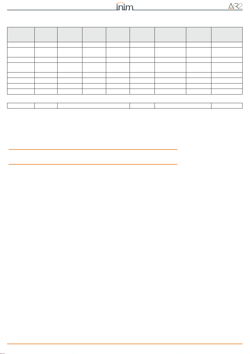
Table 6: Pattern - default
Description
of pattern Activate
sounder Sounder
duration Tone Volume Activate
flasher Flasher dura-
tion Flash type Activate
STATUS LED
PRG LED
Burglary ON 3 minutes Tone 1 High ON 3 minutes 56 OFF
Burglary low
volume ON 4 minutes Tone 1 Low ON 4 minutes 56 OFF
Fire ON 3 minutes Tone 3 High ON 3 minutes 56 OFF
Tam pe r ON 127
seconds Tone 1 High ON 127 seconds 36 OFF
Pre-alarm ON 30 seconds Tone 1 Low ON 30 seconds 36 OFF
Automation ON 3 seconds Tone 1 Low OFF OFF
Signalling ON 1 second Tone 3 Low ON 3 seconds 56 OFF
Chime ON 3 seconds Tone 3 Low ON 3 seconds 56 OFF
A Cut-off pattern can be:
Total cut off OFF ininfluent OFF ininfluent OFF

12 Declaration of conformity
Hedera Wireless sounder/flasher
Appendix A
DECLARATION OF
CONFORMITY
Hereby, INIM Electronics s.r.l. declares that this Air2-Hedera is in compliance with the
essential requirements and other relevant provisions of Directive 1999/5/EC.
Declarations of Performance, Declarations of Conformity and Certificates
concerning to INIM Electronics S.r.l. products may be downloaded free of charge
from the web address www.inim.biz, getting access to Extended Access and then
selecting "Certifications" or requested to the e-mail address info@inim.biz or
requested by ordinary mail.

Information about disposal of batteries and accumulators 13
Installation and programming manual
Appendix B
INFORMATION ABOUT DISPOSAL OF
BATTERIES AND ACCUMULATORS
(Applicable in Countries with separate collection systems)
This marking on batteries and/or their manual and/or their packaging, indicates
that batteries of these products, at the end of their working life, should not be
disposed of as unsorted municipal waste, but must be object of a separate
collection. Where marked, the chemical symbols Hg, Cd o Pb indicate that the
battery contains mercury, cadmium or lead above the reference levels of the
directive 2006/66/EC. If batteries are not properly disposed of, these substances,
together with other ones contained, can cause harm to human health and to the
environment.
To protect human health and the environment, to facilitate treatment and
recycling of materials, separate batteries from other kind of waste and use the
collection scheme stated in your area, in accordance to current laws.
Before disposing of the above, it's appropriate to remove them from their holders
avoiding to damage them or causing short circuits.
DCMIINE0A2HEDERAV8-R110-20170302

14 Information about disposal of batteries and accumulators
Hedera Wireless sounder/flasher
15
Installation and programming manual
Notes

16
Hedera Wireless sounder/flasher
Centobuchi, via Dei Lavoratori 10
63076 Monteprandone (AP) Italy
Tel. +39 0735 705007 _ Fax +39 0735 704912
ISO 9001 Quality Management
certified by BSI with certificate number FM530352
Other manuals for Air2 Series
3
This manual suits for next models
2
Table of contents
Other INIM Electronics Marine Equipment manuals

INIM Electronics
INIM Electronics Air2 Series Assembly instructions

INIM Electronics
INIM Electronics enea ES2050 User manual

INIM Electronics
INIM Electronics enea ESB1050 User manual

INIM Electronics
INIM Electronics FireVibes WSB1010 User manual

INIM Electronics
INIM Electronics IVY series Assembly instructions

INIM Electronics
INIM Electronics iris ISB1050 User manual


