iXBlue GAPS User manual

GAPS
Positioning System
User Guide


GAPS -User Guide
Revision History
Edition Date Comments
F 5/2016 Pack Soft 6
G 3/2018 Pack Soft 7
H 11/2019 Pack Soft 8
MU-GAPS-AN-005-H - November 2019 3

GAPS -User Guide
Copyright
All rights reserved. No part of this manual may be reproduced or transmitted, in any form or by
any means, whether electronic, printed manual or otherwise, including but not limited to
photocopying, recording or information storage and retrieval systems, for any purpose without
prior written permission of iXblue.
Disclaimer
iXblue specifically disclaims all warranties, either expressed or implied, included but not
limited to implied warranties of merchantability and fitness for a particular purpose with
respect to this product and documentation. iXblue reserves the right to revise or make
changes or improvement to this product or documentation at any time without notify any
person of such revision or improvements.
In no event shall iXblue be liable for any consequential or incidental damages, including but not
limited to loss of business profits or any commercial damages, arising out of the use of this
product.
4MU-GAPS-AN-005-H - November 2019

GAPS -User Guide
Warranty
iXblue provides a standard warranty of one (1) year covering this product against any defect in
materials or manufacture. The warranty starts from the date of shipment of the product from
iXblue’s manufacturing premises to customer’s location and its duration is indicated in the
certificate of warranty delivered with the product. In the event that a defect in materials or
manufacture becomes obvious during the stipulated warranty period, iXblue will undertake, at
its sole discretion, either to repair the defective product, bearing the cost of all parts and labor,
or to replace it with an identical product.
In order to avail itself of this warranty, Customer must notify iXblue of the defect before expiry
of the warranty period and take all steps necessary to enable iXblue to proceed. Customer
shall be responsible for the packaging and the shipment of the defective product to the repair
center notified by iXblue, the cost of such shipment being borne by Customer. iXblue agrees
to bear the cost of return freight, based on CPT (Cost Paid To) Customer’s airport location,
import tax-free.
This warranty shall not be construed as covering defects, malfunctions or damages caused by
improper use or inadequate maintenance of the product. Under no circumstances shall iXblue
be due to provide repair or replacement under this warranty in order a) to repair damage caused
by work done by any person not representing iXblue for the installation, repair or maintenance
of the product ; b) to repair damage caused by improper use or connection to incompatible
equipment, and specifically, the opening of the housing of the equipment under warranty shall
cause the warranty to be automatically canceled ; c) to maintain any product that has been
modified or integrated into a larger configuration, if such modification or integration increases
the duration or difficulty of the maintenance of said product.
This warranty covers the product hereunder and is provided by iXblue in place of all and any
other warranty whether expressed or implied. iXblue does not guarantee the suitability of the
product under warranty for sale or any specific use. iXblue’s liability is limited to the repair or
replacement of defective products, this being the sole remedy open to Customer in the event
the warranty becomes applicable. iXblue cannot be held liable for indirect, special, subsequent
or consequential damage, irrespective of whether iXblue has or has not received prior
notification of the risk of occurrence of such damage.
MU-GAPS-AN-005-H - November 2019 5

GAPS -User Guide
Export Regulation
iXblue products and services shall not be exported or re-exported in the following countries
(including their territorial waters): Cuba, Iraq, Iran, North Korea, Sudan and Syria.
The following export control guidelines shall apply as related to French rules and regulations.
Dual-use goods This product or service belongs to the dual-use goods category, it has not been specifically
developed for military applications but may be used in the scope of either civilian or military
applications. It is then concerned by the dispositions of Regulation (EC) N° 428/2009 of the
Council of 5th May 2009 as modified, directly applicable in French law.
As a consequence, this product or service is subject to the following dual-use goods export
control procedures from France:
●It can be freely delivered to France or any country within EU.
●It can be exported under iXblue’s Union General Export Authorization n° EU001 to the
following countries (so called “bona fide”): Australia, Canada, USA, Japan, New-
Zealand, Norway and Switzerland / Liechtenstein.
●It can be exported to other countries but only through the preliminary issuance of an
individual export license by the French authorities.
If an individual export license has to be issued by the French authorities, it is required that you
provide a description of your usual activity (and the one of the end-user if different) and that the
end-user fills in an end-user certificate (using a predefined format). This certificate includes the
description and location of the intended application for the product or service as well as a
commitment not to re-export the said product or service without the preliminary agreement of
the French authorities.
Once the product or service has been delivered to its first destination, the following rules
apply:
●From an EU country member, the good is free of movement as long as it remains within
EU.
●From an EU country member, the good can only be re-exported to a non EU country
member under the dual-use goods export control procedures set forth by the local national
authorities.
●From a “bona fide” country, the good can only be re-exported under the dual-use goods
export control procedures set forth by the local national authorities.
●From another country, the good can only be re-exported under both the conditions of the
original export license from France (depending on its type and content) and the dual-use
goods export control procedures set forth by the local national authorities.
6MU-GAPS-AN-005-H - November 2019

GAPS -User Guide
Guide Overview
This document is the User Guide for GAPS. It must be read and understood prior to using the
GAPS system. The manufacturer shall in no case be held liable for any application or use that
does not comply with the stipulations in this guide. GAPS User Guide is divided into the
following parts:
●Introduction - This section contains a general and technical description of GAPS.
●Conventions and Specifications - This section gathers all important information about
reference center, reference axes, signs of attitude angles etc.
●Installing GAPS - In this section, you find the procedure to install the GAPS system, to
assess its geometrical configuration parameters, and to plan all connections to external
systems.
●Configuring GAPS - In this section, you find the procedure for configuring GAPS with
the help of the Web-based User interface. It describes all required parameters before
operating the system.
●Setting GAPS to Work - This section gathers all tasks that have to be gone through
before the start of the survey.
●Visualizing GAPS Data with DELPH RoadMap - This section describes how to use
DELPH RoadMap software in order to visualize USBL data coming out of GAPS.
●Coupling GAPS and Subsea INS - This section describes the connection between
GAPSand a subsea INS installed on an ROV.
●Dynamic Positioning Modes - This section details the operation of GAPS in conjunction
with a dynamic positioning system.
●Operating GAPS - This section provides the full description of operation of GAPS.
●Maintenance - This section provides the preventative and corrective maintenance for
GAPS.
MU-GAPS-AN-005-H - November 2019 7
GAPS -User Guide
Abbreviations and Acronyms
AHRS Attitude and Heading Reference System
AUV Autonomous Unmanned Vehicle
CAF Common Acknowledgment Frequency
CIF Common Interrogation Frequency
CRF Common Reply Frequency
CRP Central Reference Point
DVL Doppler Velocity Log
IIF Individual Interrogation Frequency
INS Inertial Navigation System
IRF Individual Response Frequency
GPS Global Positioning System
HRP Heading Roll Pitch
LBL Long Base Line
LED Light Emitting Diode
MFSK Multiple Frequency Shift Keying
MMI Man Machine Interface
PHINS PHotonic Inertial Navigation System
ROV Remote Operated Vehicle
RT Release Transponder
RTK Real Time Kinematic
SIN Spectral Isotropic Noise
SLAM Simultaneous Localization And Mapping
USBL Ultra Short Base Line
UTC Universal Time Coordinated
8MU-GAPS-AN-005-H - November 2019
GAPS -User Guide
Text Usage
Bold Bold text is used for items you must select or click in the software. It is
also used for the field names used into the dialog box
Courier
Text in this font denotes text or characters that you should enter from the
keyboard, the proper names of disk drives, paths, directories, programs,
functions, filenames and extensions
Italic Italic text is the result of an action in the procedures. It is also used for ref-
erencing to other document titles
Icons
The Note icon indicates that the following information is of particular interest
and should be read with care.
Important
The Important mention indicates that the following information should be read
to forbid or prevent a product dysfunction or a faulty operation of the equip-
ment.
The Caution icon indicates that the following information should be read to for-
bid or prevent product damage.
The Warning icon indicates that possible injury or death could result from fail-
ure to follow the provided recommendation.
MU-GAPS-AN-005-H - November 2019 9

GAPS -User Guide
Table of Contents
1 INTRODUCTION 16
1.1 PRINCIPLE 16
1.2 EQUIPMENT DESCRIPTION 17
1.2.1 Overview 17
1.2.2 GAPSHead 18
1.2.3 GAPSBOX 19
1.2.4 Web-Based UserInterface 19
1.2.5 Acoustic Transponders 20
1.2.6 Optional Integrated DGPS 21
1.2.7 USBL Telemetry 21
1.2.8 Ping Stacking 21
1.2.9 Optional HiSys Hoisting System 21
2 CONVENTIONS AND SPECIFICATIONS 23
2.1 CONVENTIONS 23
2.1.1 Center of Measurements, Acoustic Center and Reference Axes 23
2.1.2 Hydrophones and Reference Frame 23
2.1.3 Attitude 24
2.2 SPECIFICATIONS OF GAPSACOUSTIC ANTENNA 25
2.2.1 General Characteristics 25
2.2.1.1 Positioning 25
2.2.1.2 Operating /Environment 25
2.2.2 Mechanical Specifications 25
2.2.3 Electrical Specifications 26
2.2.3.1 Main Cable 26
2.2.3.2 Optional Repeater Box for the Main Cable 28
2.2.3.3 Optional GAPS GPS Cable 30
2.2.3.4 Optional GAPSY Cable 30
2.2.3.5 GAPSBox 32
2.2.3.6 Power Supply 34
2.2.3.7 Synchronization Signals 35
2.2.3.8 Serial Link Wirings 35
3 INSTALLING GAPS 36
3.1 CHECKING THE DELIVERY 36
3.2 INSTALLING THE ACOUSTIC ANTENNA 37
3.2.1 Recommendations 37
3.2.1.1 Cable Curvature 37
3.2.1.2 Environmental Noise 37
3.2.1.3 Reflective Surfaces 37
3.2.1.4 Corrosion 38
3.2.2 Principles 38
3.3 INSTALLING THE GAPS BOX 40
3.3.1 Electromagnetic Compatibility Recommendations 40
3.3.2 Cable Curvature 40
3.3.3 Connecting the Box 41
10 MU-GAPS-AN-005-H - November 2019
GAPS -User Guide
3.4 INSTALLING THE GPS ANTENNA 42
3.4.1 Installing an External GPS 42
3.4.2 Installing the Optional iXblue DGPS 43
3.4.3 Identifying the GPS Lever Arms 44
3.4.3.1 GPS Antenna above GAPS 44
3.4.3.2 GPS Antenna not above GAPS 45
3.4.4 GPS Time 46
3.5 INSTALLING THE TRANSPONDERS 46
4 CONFIGURING GAPS 47
4.1 WEB-BASED USER INTERFACE GENERAL OVERVIEW 47
4.1.1 Main Window 48
4.1.2 Windows and Menus Handling 49
4.1.3 Logo Handling 49
4.1.4 Color Code 50
4.1.5 General Rules for Using Command Windows 51
4.1.6 Web-Based User Interface Options 52
4.1.7 Saving and Restoring the Settings and Options 54
4.1.7.1 Saving the Settings 54
4.1.7.2 Restoring the Settings or Loading Options 55
4.2 CONFIGURING THE NETWORK 56
4.2.1 Connecting the System Directly to a Computer 56
4.2.1.1 Default IP Address 56
4.2.1.2 Configuring the Computer 57
4.2.2 Connecting GAPS to a Local Network 59
4.2.2.1 Configuring GAPS Network Interface 60
4.2.2.2 Connection Procedure 61
4.3 CONFIGURING THE ACOUSTIC ANTENNA 62
4.4 CONFIGURING THE INPUT AND OUTPUT PARAMETERS 64
4.4.1 Configuring the Inputs 64
4.4.1.1 Input Stream Parameters 64
4.4.1.2 Configuring the Position Input 65
4.4.1.3 Configuring the UTC Input 67
4.4.1.4 Configuring the Pressure Input 68
4.4.1.5 Configuring the Telemetry 69
4.4.1.6 Configuring the Hoisting System 70
4.4.2 Configuring the Outputs 71
4.4.2.1 Output Stream Parameters 71
4.4.2.2 Configuration Procedure 72
4.5 CONFIGURING THE INTERNAL INSOF GAPS 73
5 SETTING GAPS TO WORK 74
5.1 DEFINING THE TRACKING PARAMETERS 74
5.1.1 Synchronization Modes 74
5.1.2 Recurrence and Blanking Time 75
5.1.3 Internal Synchronization 76
5.1.4 External Synchronization 77
5.1.5 Ping Stacking 78
MU-GAPS-AN-005-H - November 2019 11

GAPS -User Guide
5.1.5.1 Description 78
5.1.5.2 Procedure 79
5.1.5.3 Ping Stacking Limitations 79
5.2 ENTERING A SOUND VELOCITY PROFILE 80
5.2.1 Loading a Profile from a Data File 80
5.2.2 Entering Manually a Profile 81
5.3 SETTING UP THE TRANSPONDERS 83
5.3.1 Adding a Transponder 86
5.3.2 Configuring a Transponder 87
5.3.2.1 Parameters 87
5.3.2.2 Procedure 89
5.3.3 Activating a Transponder 91
5.3.4 Deleting a Transponder 91
6 VISUALIZING GAPS DATA IN DELPH ROADMAP 92
6.1 INTRODUCTION 92
6.2 DELPH ROADMAP FEATURES 93
6.2.1 Navigation Menu 93
6.2.2 Toolbars and Panels 93
6.2.2.1 Equipment Toolbar 94
6.2.2.2 Panels 94
6.2.2.3 Mobile Toolbar 96
6.3 REAL-TIME MODE 97
6.3.1 Defining an Equipment 97
6.3.2 Configuring the Connection 98
6.3.3 Configuring the Logging 100
6.3.4 Connecting Equipment and Logging Data 101
6.3.5 Editing the Display 103
6.4 REPLAY MODE 105
6.4.1 Importing a Navigation Data File 105
6.4.2 Replaying a Dataset 106
6.5 VISUALIZATION TOOLS 107
6.5.1 Mobile Immersion 107
6.5.2 Vertical Axis 108
6.5.3 Range Circle 109
6.5.4 Uncertainty Ellipse 110
6.5.5 LBL Range 111
6.5.6 North Oriented View 113
6.5.7 Heading Oriented View 114
6.5.8 Mobile Information 115
6.5.9 Relative Positioning 116
6.5.10 Event Marks 117
6.5.10.1 Creating an Event Mark 117
6.5.10.2 Managing Event Marks 119
6.5.11 Waypoints 120
6.5.11.1 Creating a Waypoint 120
6.5.11.2 Managing Waypoints 122
12 MU-GAPS-AN-005-H - November 2019

GAPS -User Guide
6.5.12 Measurements 123
6.5.12.1 Creating a Measurement 123
6.5.12.2 Managing the Measurements 125
6.5.13 Exporting a Trajectory 126
7 COUPLING GAPS AND SUBSEA INS 128
7.1 LIST OF IXBLUE SUBSEA INS 128
7.2 COUPLING PRINCIPLE 129
7.3 PROCEDURES 131
7.3.1 Output Configuration in GAPS Web-based User Interface 131
7.3.2 Input Configuration in the Subsea INSWeb-based User Interface 132
7.4 COUPLING USING MTBX2 ACOUSTIC COMMUNICATION 134
8 DYNAMIC POSITIONING MODES 135
8.1 DEFINITION 135
8.2 L-USBL MODE 136
8.3 L-USBL-INS MODE 137
8.4 PROCEDURE 139
9 OPERATING GAPS 141
9.1 DEPLOYING THE TRANSPONDERS 141
9.2 LAUNCHING THE SURVEY 141
9.2.1 Initializing the INS 141
9.2.2 Initializing GAPS 143
9.3 CONTROLLING THE DATA 144
9.3.1 Data Control Windows 144
9.3.1.1 CONTROL Window 145
9.3.1.2 NAVIGATION Window 146
9.3.2 Checking the Current Voltage of a ZTA02C Transponder 147
9.3.3 Deselecting a Channel for a USBL Computation 148
9.3.4 List and Meanings of Status, Warning and Errors 149
9.3.5 Frequency Spectrum of the Hydrophones 151
9.3.6 Controlling Data Acquisition using iXblue Multilogger 152
9.4 RECOVERING THE EQUIPMENT 154
9.4.1 Recovering GAPS 154
9.4.2 Recovering Transponders with the Telecommand 154
10 MAINTENANCE 156
10.1 PREVENTIVE MAINTENANCE 156
10.1.1 General Recommendations 156
10.1.2 Checking the Electrical Ground 158
10.1.3 Connecting a new GAPS BOX to GAPS 159
10.1.4 Maintaining SUBCONN Connectors 160
10.2 MAINTENANCE FROM THE WEB-BASED USER INTERFACE 161
10.2.1 Calibrating the GAPS Acoustic Antenna 161
10.2.2 Updating the System 161
10.2.3 Checking the Currently Installed Options 162
10.2.4 Resetting the System to Factory Settings 162
10.2.5 Contacting iXblue Technical Support 163
MU-GAPS-AN-005-H - November 2019 13

GAPS -User Guide
IXBLUE CONTACT - SUPPORT 164
IXBLUE CONTACT - SALES 164
APPENDICES 165
A PREVENTING JAVA SECURITY WARNING DIALOG BOX 165
B RESTRICTIONS ON IP, GATEWAY AND MASK 167
C THIRD PARTY TRANSPONDER CODES 168
D SONARDYNE WIDEBAND® 1 TRANSPONDERS 170
E SETTINGS EXAMPLES 171
E.1 ONE TRANSPONDER 171
E.2 TWO TRANSPONDERS - SAME INTERROGATION CODE 171
E.3 TWO TRANSPONDERS - TWO INTERROGATION CODES 172
E.4 FOUR TRANSPONDERS - THREE INTERROGATION CODES 173
E.5 FOUR TRANSPONDERS - FOUR INTERROGATION CODES - TWO REPETITION FACTORS 174
F CONFIGURING QINSY CONNECTED TO GAPS 175
G NMEA CHECKSUM DEFINITION 176
H INPUT PROTOCOLS 177
H.1 GPS 177
H.2 PRESSURE DATAGRAM PMEVL 179
H.3 ITSTELEMETRY 180
H.4 HOISTING SYSTEM 181
I OUTPUT PROTOCOLS WITH TRANSPONDER(S) POSITION 182
I.1 MINIMUM OUTPUT RECURRENCE VS. BAUD RATE 182
I.2 BLANKING TIME AND RECURRENCE EXAMPLES 183
I.3 CONTENTS OF VARIOUS DATAGRAMS 184
I.4 DATASTANDARD 186
I.4.1 PTSAG 186
I.4.2 PTSAX 187
I.4.3 PTSAY 188
I.4.4 PTSAZ 189
I.4.5 PTSAH 189
I.4.6 PIXOG 190
I.4.7 PTSAQ 190
I.4.8 PIXSE,LABEL 191
I.5 DATA LEGACY 192
I.6 DATA PTSAG 192
I.7 GAPS STANDARD 193
I.8 GAPS STANDARD ALTITUDE 197
I.9 GAPS STANDARD TRANSPONDER 200
I.10 DATA LIGHT 200
I.11 HIPAP HPR 400 201
I.12 HIPAP HPR 418 (FIX AND MOBILE) 202
I.13 HPR BCD 205
I.14 IXSEA USBL INS 1 211
I.15 IXSEA USBL INS 2 213
14 MU-GAPS-AN-005-H - November 2019

GAPS -User Guide
I.16 NAUTRONIX ATS II 215
I.17 POSIDONIA 6000 216
I.18 USBL_POSTPRO 217
I.19 PIFM-POPSN 226
J GAPS PHINS LEVER ARM 226
K OUTPUT PROTOCOLS WITH INS POSITION 227
L GAPS ANTENNA MECHANICAL DRAWING 229
M MAIN CABLE REPEATER BOX MECHANICAL DRAWING 230
N GAPS BOX MECHANICAL DRAWING 231
O RACKABLE GAPS BOX MECHANICAL DRAWING 232
MU-GAPS-AN-005-H - November 2019 15

GAPS -User Guide
1 Introduction
1.1 Principle
The Global Acoustic Positioning System GAPS is a portable Ultra Short Base Line (USBL)
with integrated Inertial Navigation System (INS) and Global Navigation Satellite System
(GNSS).
Plug and Play The GAPS system is recommended for mobile or fixed installations. It can be combined with
an additional hoisting system. It is a plug & play installation. No calibration is required before
using GAPS.
Accuracy The GAPS system is used to deliver:
●The position of one or more underwater objects or vehicles, which can maneuver at depth
up to 3,000 meters. Deeper is possible depending on the type of beacon used.
●The accuracy is up to 0.06 % accuracy of the slant range depending on environmental and
operational conditions.
●The heading, attitude, motion and position of the support vessel or buoy.
Operation
Principles The underwater objects or vehicles are tracked using acoustic transponders. The GAPS
antenna is deployed underwater and is usually mounted below the ship hull.
Figure 1 - GAPS typical mounting
16 MU-GAPS-AN-005-H - November 2019

GAPS -User Guide
1.2 Equipment Description
1.2.1 OVERVIEW
Figure 2 - Two possible architectures
Elements The GAPS system consists of the following elements:
●GAPS head, 1.2.2
●GAPS BOX connects GAPS and the other system elements, 1.2.3
●Web-based User Interface is used to configure (mandatory) and to monitor (optional) the
real time data, 1.2.4
●Up to 40 moored or mobile acoustic transponders, 1.2.5
●Optional integrated DGPS antenna provides absolute positions of the ship to GAPS
Cables Three cables are used in the GAPS system:
●Main cable links GAPS to the BOX
●Optional Y cable connects the GPS and the BOX directly to the GAPS.
●Optional GPS cable links the Y cable to the GPS antenna.
User GPS If the expected accuracy of an external GPS is better than the GAPS integrated DGPS, it is
possible to connect it to the BOX (through the External GPS RS 232 serial link) and to use its
positioning data. In that case, the “Y” cable is not used.
MU-GAPS-AN-005-H - November 2019 17

GAPS -User Guide
1.2.2 GAPSHEAD
Figure 3 - GAPS Head
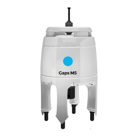
Description The GAPS head is equipped with carbon housing. It is composed of:
●An upper flange for handling and fastening
●A central transmission transducer
●Four reception hydrophones of different lengths to take 3D measurements
●The four hydrophones are protected by plastic caps
●A SUBCONN connection plug
Contents The GAPS head contains:
●The acoustic electronics for reception based on the MSFK Chirp modulation technique
●An Inertial Navigation System (INS)
●The acoustic transmitter electronics
GAPS Head The GAPS head ensures
●The acoustic transmission or electrical triggering signals to the Transponders
●The reception of the replies
●The processing taking into account the attitude provided by the fiber-optic sensor
●The transmission of the results
Maximum speed with deployed GAPS antenna: 12 knots.
18 MU-GAPS-AN-005-H - November 2019

GAPS -User Guide
1.2.3 GAPSBOX
The GAPS BOX connects together all the different elements of the system. The GAPS head
and the external sensors (GPS, Synchronization) are directly connected to the BOX. The ship
power supply is provided to the BOX. Ethernet and serial links connectors are available for
data output. The GAPS BOX is necessary to the operation of GAPS.
Figure 4 - GAPS BOX
Connectors Below are listed the connectors of the GAPS BOX:
●Ethernet: control / command and four input and output links
●Four input and output serial links
●Two synchronization outputs and one synchronization input
●One PPS link
●Power supply VDC / AC
Rack option On customer request, the GAPS BOX can be rackable (19''rack). See appendix O.
1.2.4 WEB-BASED USERINTERFACE
The Web-based user interface is a web application enabling configuration of the system (lever
arms, management of connections, celerity profile, configuration and management of
transponders) before each mission and checking the data input during the mission. This
application also enables recording of data and the sending of signals for the remote control.
4.1.
Figure 5 - Main window of the Web-based user interface
MU-GAPS-AN-005-H - November 2019 19

GAPS -User Guide
1.2.5 ACOUSTIC TRANSPONDERS
The transponders compatible with GAPS are listed below. Please report to specific User
guides of the transponder. Contact iXblue to know if compatibility exists with other models.
Table 1 - GAPS compatible transponders
iXblue MT8
iXblue MT9
iXblue ET / RTAx2
iXblue ZTA02C
iXblue RAMSES
iXblue CANOPUS
iXblue STAx2
iXblue MTBx2
Applied 1019 software permitting *
Sonardyne Mini beacon 5 & 6 Sonardyne
Wideband® 1 compatible
Sonardyne Compatt 5 & 6 Sonardyne
Wideband® 1 compatible
* Only the “software permitting”. Make sure your Applied beacon has the iXblue codes
compatibility before operating.
20 MU-GAPS-AN-005-H - November 2019
Other manuals for GAPS
3
Table of contents
Other iXBlue Marine Equipment manuals
Popular Marine Equipment manuals by other brands

Humphree
Humphree LIGHTNING L300 installation manual

MOFLASH SIGNALLING
MOFLASH SIGNALLING SB150-1 Series INSTALLATION & TECHNICAL INFORMATION

Risco
Risco WL S52 Installation and programming instructions

Roca
Roca W12 Mounting instructions

Simrad
Simrad ES80 Reference manual

Furuno
Furuno FCV-30 installation manual

Furuno
Furuno FELCOM18 installation manual

Raymarine
Raymarine St290 Owner's handbook

Eaton
Eaton X 10 DC Quick install guide

Furuno
Furuno Multi Instrument FI-504 Operator's manual

Parker
Parker Sea Recovery ULTROClear Series Installation operation & maintenance

NKE
NKE CARBOWIND HR USER GUIDE and INSTALLATION GUIDE