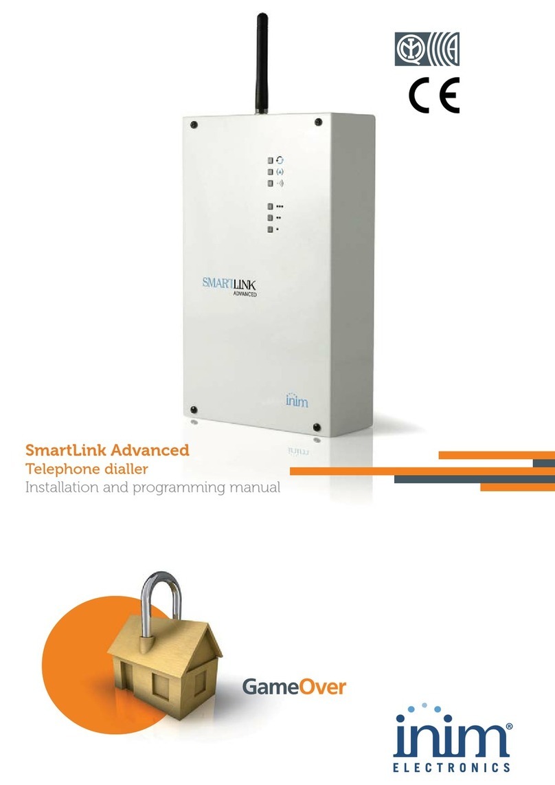
INIM Electronics SmartLink Advanced Series Assembly instructions

1
Installation and programming manual
SmartLink Advanced
Telephone dialler
Installation and programming manual
EN 50131-1
EN 50131-10
EN 50136-1
EN 50136-2
EN 50130-4
EN 50130-5
CEB T014

2
Telephone dialler
Warranty
INIM Electronics s.r.l. (Seller, Our, Us) warrants the original
purchaser that this product shall be free from defects in materials
and workmanship under normal use for a period of 24 months. As
INIM Electronics s.r.l. does not install this product directly, and due
to the possibility that it may be used with other equipment not
approved by Us; INIM Electronics s.r.l. does not warrant against loss
of quality, degradation of performance of this product or actual
damage that results from the use of products, parts or other
replaceable items (such as consumables) that are neither made nor
recommended by INIM Electronics. Seller obligation and liability
under this warranty is expressly limited to repairing or replacing, at
Seller's option, any product not meeting the specifications. In no
event shall INIM Electronics s.r.l. be liable to the purchaser or any
other person for any loss or damage whether direct or indirect or
consequential or incidental, including without limitation, any
damages for lost profits, stolen goods, or claims by any other party
caused by defective products or otherwise arising from the incorrect
or otherwise improper installation or use of this product.
This warranty applies only to defects in parts and workmanship
relating to normal use. It does not cover:
• damage arising from improper maintenance or negligence
• damage caused by fire, flood, wind or lightning
• vandalism
• fair wear and tear
INIM Electronics s.r.l. shall, at its option, repair or replace any
defective products. Improper use, that is, use for purposes other
than those mentioned in this manual will void the warranty. Contact
Our authorized dealer, or visit our website for further information
regarding this warranty.
Limited
warranty
INIM Electronics s.r.l. shall not be liable to the purchaser or any
other person for damage arising from improper storage, handling or
use of this product.
Installation of this Product must be carried out by qualified persons
appointed by INIM Electronics. Installation of this Product must be
carried out in accordance with Our instructions in the product
manual.
Copyright
The information contained in this document is the sole property of
INIM Electronics s.r.l. No part may be copied without written
authorization from INIM Electronics s.r.l.
All rights reserved.
Directive
1999/5/CE
(R&TTE)
compliance
Hereby INIM Electronics s.r.l. declares that the SmartLinkAdv/P,
SmartLinkAdv/G and SmartLinkAdv/GP are in compliance with the
essential requirements and other relevant provisions of Directive
1999/5/CE.
The full declarations of conformity of the above-mentioned devices
are available at URL:
www.inim.biz/certifications

3
Installation and programming manual
Table of
contents
Warranty . . . . . . . . . . . . . . . . . . . . . . . . . . . . . 2
Limited warranty . . . . . . . . . . . . . . . . . . . . . . . . 2
Copyright . . . . . . . . . . . . . . . . . . . . . . . . . . . . . 2
Directive 1999/5/CE (R&TTE) compliance . . . . . . . 2
Table of contents. . . . . . . . . . . . . . . . . . . . . . . . 3
About this manual . . . . . . . . . . . . . . . . . . . . . 5
0-1 Terminology . . . . . . . . . . . . . . . . . . . . . . . . . . . . . . . 5
0-2 Graphic conventions . . . . . . . . . . . . . . . . . . . . . . . . . 5
Chapter 1 General information . . . . . . . . . . . . . . . . . . . . 6
1-1 Manufacturer's details . . . . . . . . . . . . . . . . . . . . . . . . 6
1-2 Description of the product and various models . . . . . . . 6
1-3 Supplied documentation. . . . . . . . . . . . . . . . . . . . . . . 8
Chapter 2 Device description . . . . . . . . . . . . . . . . . . . . . 9
2-1 Unpacking the device. . . . . . . . . . . . . . . . . . . . . . . . . 9
2-2 Accessory items . . . . . . . . . . . . . . . . . . . . . . . . . . . . 9
2-3 Technical description . . . . . . . . . . . . . . . . . . . . . . . . . 9
2-4 Signalling from device . . . . . . . . . . . . . . . . . . . . . . . . 11
Chapter 3 SmartLinkAdv functions . . . . . . . . . . . . . . . . . 13
3-1 Telephone line down management . . . . . . . . . . . . . . . 13
3-2 Input/Output terminals . . . . . . . . . . . . . . . . . . . . . . . 13
3-3 Event activations. . . . . . . . . . . . . . . . . . . . . . . . . . . . 14
3-4 Dialler function . . . . . . . . . . . . . . . . . . . . . . . . . . . . . 14
3-5 Command and Shortcuts . . . . . . . . . . . . . . . . . . . . . . 15
3-6 Remote activation . . . . . . . . . . . . . . . . . . . . . . . . . . . 15
3-7 Easyscan . . . . . . . . . . . . . . . . . . . . . . . . . . . . . . . . . 17
3-8 Jamming detector . . . . . . . . . . . . . . . . . . . . . . . . . . . 17
Chapter 4 Installation . . . . . . . . . . . . . . . . . . . . . . . . . . 18
4-1 Wall-mounting . . . . . . . . . . . . . . . . . . . . . . . . . . . . . 18
4-2 Connecting to the mains power supply. . . . . . . . . . . . . 18
4-3 Mounting the antenna . . . . . . . . . . . . . . . . . . . . . . . . 19
4-4 Telephone connections. . . . . . . . . . . . . . . . . . . . . . . . 20

4
Telephone dialler
4-5 Earth connection. . . . . . . . . . . . . . . . . . . . . . . . . . . . 20
4-6 Inserting the SIM card. . . . . . . . . . . . . . . . . . . . . . . . 20
4-7 PC Connection . . . . . . . . . . . . . . . . . . . . . . . . . . . . . 21
4-8 Wiring and balancing alarm detectors . . . . . . . . . . . . . 22
4-9 Connecting the outputs . . . . . . . . . . . . . . . . . . . . . . . 25
Chapter 5 First power up . . . . . . . . . . . . . . . . . . . . . . . . 26
5-1 Initializing phase. . . . . . . . . . . . . . . . . . . . . . . . . . . . 26
5-2 Easyscan procedure. . . . . . . . . . . . . . . . . . . . . . . . . . 26
Chapter 6 Project development and programming. . . . . . . 28
6-1 Using the SmartLeague software program . . . . . . . . . . 28
6-2 Using the software program . . . . . . . . . . . . . . . . . . . . 29
6-3 Programming via the software . . . . . . . . . . . . . . . . . . 30
6-4 Reset default settings . . . . . . . . . . . . . . . . . . . . . . . . 31
6-5 Maintenance and monitoring. . . . . . . . . . . . . . . . . . . . 31
Chapter 7 EN50136 Compliance . . . . . . . . . . . . . . . . . . . 33
7-1 ATS Categories . . . . . . . . . . . . . . . . . . . . . . . . . . . . . 33
7-2 Access Levels . . . . . . . . . . . . . . . . . . . . . . . . . . . . . . 34
7-3 Connection with alarm control panel (Control and Indicating Equipment) 34
Appendix A Events . . . . . . . . . . . . . . . . . . . . . . . . . . . . . 36
Appendix B Declaration of conformity . . . . . . . . . . . . . . . . 38
Notes . . . . . . . . . . . . . . . . . . . . . . . . . . . . . . . . 39

About this manual 5
Installation and programming manual
ABOUT THIS MANUAL
MANUAL CODE
DCMIINE0SLINKA
VERSION
1.70
0-1Terminology
DIALER
A device which sends voice calls or digital reports to programmed
contact numbers in the event of an alarm.
DEVICE
If not otherwise specified, refers to the SmartLinkAdv.
QUALIFIED
PERSONNEL
Persons whose training, expertise and knowledge of the products and
laws regarding security systems, are able to create, in accordance with
the requirements of the purchaser, the most suitable solution for the
protected premises.
LEFT, RIGHT, BEHIND,
ABOVE, BELOW
Directions as seen by the operator when directly in front of the
mounted device.
SELECT
Click on a specific item on the interface (drop-down menu, options
box, graphic object, etc.).
PRESS
Click on a video button, or push a key on the control-panel keypad.
0-2Graphic conventions
Following are the graphic conventions used in this manual.
Note
The “Note” sections contain important information relating to the text.
ATTENTION!
The “Attention” prompts indicate that total or partial disregard of
the procedure could damage the device or its peripherals.
Conventions Example Description
Text in italics Refer to paragraph 0-2 Graphic
conventions Indicates the title of a chapter, section,
paragraph, table or figure in this manual
or other published reference.
Text in boldface
menu ?
,
Information
Indicates the title of a section, key or
software item
<text> #<AccountCode> Editable field

6General information
Telephone dialler
Chapter 1
GENERAL INFORMATION
1-1Manufacturer's details
Manufacturer: INIM Electronics s.r.l.
Production plant: Centobuchi, via Dei Lavoratori 10
63076 Monteprandone (AP), Italy
Tel: +39 0735 705007
Fax: +39 0735 704912
e-mail: [email protected]z
Web: www.inim.biz
The persons authorized by the manufacturer to repair or replace the
parts of this system, hold authorization to work on INIM Electronics
brand devices only.
1-2Description of the product
and various models
DESCRIPTION
The SmartLink device described in this manual is a reserve
telephone line generator and telephone dialler.
RESERVE TELEPHONE
LINE
If problems occur on the PSTN (linedown conditions, etc.), the
SmartLinkAdv will guarantee communications by switching to a GSM
provider and allowing any connected devices to operate normally.
When the SmartLinkAdv operates as a simulated line, it tests the PSTN
line periodically to check if the communication problems have cleared.
If the PSTN line is found to be operating normally and there are no
ongoing telephone calls passing through the interface, the system will
switch back to the main PSTN line. Otherwise, it will switch back to the
PSTN only when all the necessary outgoing calls have been forwarded.
TELEPHONE DIALLER
SmartLinkAdv generates a series of operations (e.g. calls, output
commands) in relation to internal events (e.g. low battery) or
external events (e.g. input status changes, received call, received
SMS commands).
OTHER FUNCTIONS
• Status control and output actions via SMS messages
• Output control and output actions via calls using the voice menu
• Output actions via Caller ID recognition
• Digital dialler (Ademco 10bps, Ademco 14bps, Franklin 20bps,
Radionics 40bps, Scantronic 10bps, Contact-ID, SIA-IP)
• SMS dialler
• Voice dialler
• Open tamper protection
• Jamming detector
• Easyscan (automatic search for the best GSM provider)

General information 7
Installation and programming manual
MODELS
SmartLinkAdv/GP - GSM and PSTN reserve line generator and
telephone dialler
SmartLinkAdv/G - GSM reserve line generator and telephone
dialler
SmartLinkAdv/P - PSTN telephone dialler
STANDARDS APPLIED
EN 50131-1:2006 + A1:2009,
EN 50131-10:2014,
EN 50136-1:2012,
EN 50136-2:2013,
EN 50130-4:2011 + A1:2014,
EN 50130-5:2011,
CEB T014:2013-04 (ed.3)
SECURITY RATING
Security rating 3 for SmartLinkAdv/G and SmartLinkAdv/GP models
and security rating 2 for SmartLinkAdv/P.
Table 1-1: Applications
Models
SmartLinkAdv
/P SmartLinkAdv
/G SmartLinkAdv
/GP
Reserve telephone line generator • •
On-board voice module with 15 minutes • •
Anti-intrusion function • •
Dialler over GSM network and PSTN landline and
GPRS modem ••
Dialler over PSTN landline • •
SMS dialler over GSM network • •
Manages DTMF commands over GSM network • •
Manages DTMF commands over PSTN landline • •
Priority channel choice between SM network and
PSTN landline ••
Fault signalling • • •
Incoming SMS divert • •
Actions using Caller ID • •
Manages commands via SMS with code or identifier
of the sender ••
Ring or SMS confirmation for commands receiving
via SMS ••
Warning calls for each event over GSM network and
PSTN landline ••
Manages GPRS for remote programming/monitoring • •
Manages supervision over GPRS • •
Periodic supervision between 2 SmartLinkAdv
devices ••
Manages SIA-IP and transmits information to alarm
receiving centres via the most widely used protocols ••
Answerphone with voice menu • •
Manages and signals "Roaming" status • •
EasyScan function • •
Jamming detector function • •
SIM card credit enquiry • •

8General information
Telephone dialler
1-3Supplied documentation
• Installation manual (this manual)
• SmartLeague software programming manual
The manuals are regularly supplied with the apparatus and can be
downloaded from the “Download” section of our website:
www.inim.biz.
The installation manual is included in the package. To order further
copies contact the offices at INIM Electronics.

Device description 9
Installation and programming manual
Chapter 2
DEVICE DESCRIPTION
2-1Unpacking the device
The device is packed inside a cardboard box containing:
• The SmartLinkAdv comprises a PCB mounted inside a metal box
• A bag containing the installation kit comprising:
•• Antenna
•• 10 x 3k9 Ohm 1/4W resistors
•• 10 x 6k8 Ohm 1/4W resistors
•• 4 screws to secure the cover to the metal backbox
• Installation manual (this manual)
The installation kit does not include:
• 1.2 A/h battery
• Switching power supply/battery charger
•SIMcard
Note
These items must be purchased before beginning the installation phase.
2-2Accessory items
The following accessory devices are individually packed and must be
ordered separately:
• IPS12015 Switching power supply/battery charger
• TamperNO dislodgement tamper protection
• Remote antenna for indoor use
• High-performance GSM antenna
• High-performance GSM antenna with 3m of cable for indoor use
2-3Technical description
The data label is located inside the metal box.
Following are the technical features of the devices and the
description of their components:

10 Device description
Telephone dialler
Table 2-1: Description of parts
A
Terminal board
K
Battery housing
B
Open-tamper microswitch
L
Wall-mount screw locations
C
Battery connector
M
Screw holes
D
USB connector
N
Cable entries
E
SIM card connector
O
Dislodgement-tamper microswitch location
F
Antenna connector
P
Antenna placement hole
G
Default-data reset button
H
Buzzer
I
Activity LED
J
GSM signal reception LED
A
B
C
E
F
H
D
PCB board Metal backbox
A
G
J
I
K
L
L L
L
M
M M
M
N N
P
O
Table 2-2: Terminals on the terminal board
n. icon/identifier function
1+14V
Positive power terminal
2 - 14V
Negative power terminal
3+AUX
12V Ancillary power supply
4
Power supply negative (earth or GND)
5-6-7-8-9 T1-T2-T3-T4-T5
Control panel input terminals: T1, T2, T3, T4 and T5
14
Earth connection
15-16
Internal telephone-line connection
17-18 PSTN
Landline connection

Device description 11
Installation and programming manual
2-4Signalling from device
The SmartLinkAdv also manages signalling on the LEDs and buzzer
as well as signalling events executed over-the-phone, via SMS
message, or triggered by output activations.
LEDS
The SmartLinkAdv is equipped with six signalling LEDs, the
activation of which, thanks to light guides, can be seen on the
outside of the metal box.
The table shows the meanings of the LEDs when activated:
Table 2-3: Technical specifications
Models SmartLinkAdv/P SmartLinkAdv/G SmartLinkAdv/GP
Voltage Nominal output
voltage
13.8 V ±10%
Functioning range
11 - 16 V
PCBcurrent-draw
during
standby status
40 mA 100 mA
during transmission
-300mA
maximum
70 mA 600 mA
Maximum current draw of +AUX
terminals
400 mA
Switching power supply
14V 1.05A
Backup battery
12V, 1.2Ah lead battery
with UL94HB flame class or higher
Inputs
5
Outputs total
5
Type
150 mA open-collector output
GSM frequency band
- 850, 900, 1800 and 1900 Mhz (Quad band)
Number of events recorded
1000
Operating temperature
from -10°C to + 40°C
Ambient Class
II
Dimensions (W x H x D) excluding
antenna
134 x 220 x 53 mm
Dimensions (W x H x D) including
antenna
- 134 x 300 x 53 mm
Weight
890g
Table 2-4: Technical specifications of the reserve line
Voltage
40Vdc
Loop current
25mA
Dialling tone
425Hz continuous
Engaged tone
200ms 425Hz / 200ms silent
Recognized dialling tone
DTMF
Ring voltage
90Vpp
Ring frequency
25 - 50 Hz (selectable)

12 Device description
Telephone dialler
In the event of the presence of more than one fault, LED 2 will
indicate all the faults one at a time.
ATTENTION!
Some operations (for example, calls to alarm receiving centres
using Contact-ID, SIA-IP, 10 and 20bps protocols) require that at
least two light-blue LEDs are ON solid.
The SmartLinkAdv provides further LED signalling, in addition to the
above-mentioned cases, indicated by the simultaneous lighting of
several LEDs:
• During the programming and initializing phases all six LEDs must
flash simultaneously.
• SmartLinkAdv is predisposed for the “Easyscan” function and
“Easyscan” active function (refer to paragraph 3-7 Easyscan):
successive activation in cyclic mode of all the LEDs starting from
LED 6 to LED 1.
• Incoming SMS:
successive activation in non-cyclic mode of one LED at a time
starting from LED 1 to LED 6.
BUZZER
The buzzer provides the end-user with audible signalling.
The buzzer provides entry time, exit time and command
confirmation signals (if programmed). Activation of these signals
can be configured during the programming phase.
Table 2-5: LED signalling
LED Status
Num. Colour Signalling ON OFF Slow flashing Fast flashing
1 Green Operating
status Device
operating Device initializing
2Red Fault No faults
present
Flash cycle followed by pause:
• 1 flash: general battery fault
• 2 flashes: telephone line fault
• 3 flashes: GSM network trouble
• 4 flashes: low credit warning
3Yellow
SmartLinkAdv
operating status
Communication
status
SmartLinkAdv
armed
SmartLinkAdv
disarmed and
there are no
ongoing calls
SmartLinkAdv
disarmed and one
call is ongoing
SmartLinkAdv
armed and there is
one ongoing call
4 Light blue
GSM reception
status
GSM signal quality:
•OneLEDOn:poorsignal
reception
• Two LEDs On: average signal
reception
• Three LEDs On: optimum
signal reception
One LED flashing: average signal reception
between two of the three predefined levels.
All three LEDs flashing: no GSM reception
5 Light blue
6 Light blue
Table 2-6: Signalling and signal type
Signalling Signal type
Entry time running Short pulse cycles
Entry time running Long pulse cycles
Command carried out 3 short pulses
Command not carried out 5 long pulses

SmartLinkAdv functions 13
Installation and programming manual
Chapter 3
SMARTLINKADV
FUNCTIONS
3-1Telephone line down
management
The devices that are to use the reserve line during PSTN line-down
conditions must be connected to terminals 15 and 16.
When the PSTN line is operating properly, terminals 15 and 16 are
connected internally to 17 and 18.
If, on the latter, the voltage drops below 3Vdc for 10 seconds,
SmartLinkAdv will disconnect from the PSTN line and switch to the
auxiliary line. The status of the PSTN line will be checked for restoral
every 3 minutes.
The absence of the PSTN line is signalled on the fault LED (red LED)
by 2 flashes. The signalling will activate only after the PSTN line has
been down for the programmed time.
3-2Input/Output terminals
The five terminals 5-9 can be configured individually as:
• Input zone terminal
• Double zone terminal (ZONE DOUBLING)
•Outputterminal
• Controlled output terminal (I/O)
• Unused terminal
INPUT/ZONE
An electrical input point used for the management/supervision of
signals coming from a device. The activation of the signal may cause
the SmartLinkAdv to carry out one of the following actions:
• Send an SMS message
• Send a digital protocol message
• Send a voice message
• Command an output
• Change the operating status of the SmartLinkAdv
OUTPUT
The outputs are open-collector outputs and allow the transmission of
commands to external devices (e.g. switch on lights, open gate, etc.).
The outputs can be activated by the SmartLinkAdv in response to
local and remote events (SMS message, DTMF call and Caller ID).
The standby condition of each output can be:
•Open
•Closed

14 SmartLinkAdv functions
Telephone dialler
The outputs can be configured as:
•Bistable
•Pulse
CONTROLLED OUTPUT
This is an output whose status can be controlled (activated/
deactivated) and used for other activations.
DOUBLE ZONE
An electrical input point used for the management/control of signals
coming from two devices.
The terminal the zone is connected to must be configured as a
“double input zone”. Terminals with this configuration allow the
system to distinguish between two distinct alarms coming from the
two different zones it is connected to.
3-3Event activations
The SmartLinkAdv is capable of recognizing specific external signals
coming from the PSTN or GSM network or via input terminals T1, T5
or internal signals such as “events”.
When such events occur or when they clear (reset/return to default
status), the SmartLinkAdv can implement the following activations:
•activateoutputs
• generate voice calls
• send digital protocol messages
• send SMS messages
In Appendix A, Events you can find the complete list of events
generated by the SmartLinkAdv.
3-4Dialler function
DIGITAL
The digital dialler function generates digital-protocol calls directly to
alarm receiving centres.
The available protocols are: Ademco 10bps, Ademco 14bps, Franklin
20bps, Radionics 40bps, Scantronic 10bps, Contact-ID, SIA-IP
SMS FUNCTION
The SMS dialler function generates outgoing SMS messages. The
outgoing SMS messages are sent in response to an event.
During the programming phase you can select the SMS message
type, which can be automatic, predefined by the SmartLinkAdv or
customized by the installer.
VOICE
The voice-dialler function activates outgoing calls containing
recorded voice messages.
During the programming phase you can select the voice messages,
which can be either predefined by the SmartLinkAdv or customized
by the installer.
ATTENTION!
INIM does not guarantee the total availability of all the GSM
functions described in this manual, due to the various combinations
of GSM service providers, SIM types and telephone models that may
be in use.

SmartLinkAdv functions 15
Installation and programming manual
3-5Command and Shortcuts
A command is a request from the end-user or a device to the
SmartLinkAdv to carry out one or more of its functions.
SHORTCUTS
During the programming phase of the SmartLinkAdv you can
arrange the commands into shortcuts. A shortcut is a single request
that activates a series of successive functions. If necessary, you can
define the shortcut parameter, in other words, the object of the
shortcut (e.g. define a specific output for functions such as “activate
output” shortcuts).
3-6Remote activation
All the functions of the SmartLinkAdv device can be activated from
remote locations.
Therefore, it is possible to send commands to the SmartLinkAdv by
means of:
• SMS messages
• telephone calls using Caller ID
• telephone calls assisted by a voice guide (“Answerphone”
function)
After receiving one of the above-mentioned commands, the
SmartLinkAdv will activate the associated actions.
Both commands and their associated actions can be configured
through the SmartLeague software program, in the sections relative
to the GSM network commands and user codes.
Table 3-1: Available shortcuts
description function parameter note
Arm/Disarm
Applies a preset scenario which scenario Shortcuts are available only
when the SmartLinkAdv is
programmed as an intrusion
control panel
Stop alarms
Deactivates instantly the outputs activated
by alarm and tamper events
Delete memory
Carries out a “Stop alarms” operation and,
at the same time, deletes alarm and
tamper memories.
Clear call queue
Cancels the call queue and stops ongoing
calls (if any).
Output activation
Activates one of the programmed outputs which output
Output
deactivation
Deactivates one of the programmed
outputs which output
Voice info
Starts playback of the audible message
playback that informs the user of the
device status Shortcuts available for codes
only
Status enquiry
Activates a device status enquiry; the user
will receive one or more SMS messages
containing a list of the parameter values
relating to the status. Refer to the default
commands described in
paragraph 3-6 Remote
activation
Credit enquiry
Activates balance enquiries relating to the
SIM card of the device; the user will receive
an SMS text indicating the remaining
credit.
GPRS Client
Activates the GPRS connection with the
SmartLeague software program via SMS

16 SmartLinkAdv functions
Telephone dialler
3-6-1
Commands over the
GSM network
Up to 200 actions can be programmed to activate in response to
remote GSM commands.
Each of the actions can be triggered by either an SMS command or a
Caller ID command or both.
COMMAND VIA SMS
MESSAGE
Users who wish to activate a command via SMS text must enter the
command details as follows:
<xxxxxx> <SMS Text>
where:
• <xxxxxx> stands for the user PIN
• a blank space must be keyed in after PIN entry
• <SMS text> is the identification of the command, as
programmed via software
DEFAULT COMMANDS
The following commands are predefined at default:
•“CODE” for the change of the user PIN code via SMS message;
the message text format must be:
<old PIN code> CODE <new PIN code>
•“CREDIT” for balance enquiries relating to the SIM card of the
device; the user will receive an SMS text indicating the
remaining credit.
•“STATUS” for enquiries relating to the status of the
SmartLinkAdv; the user will receive an SMS text indicating:
•• device name and firmware revision
•• GSM network provider
•• GSM signal reception level
•• Presence of the PSTN line
•• list of faults present
•• device tamper status
•• power supply of the circuit
•• armed/disarmed status of the SmartLinkAdv
•• list of zones in alarm status
•• list of terminals in tamper status
•• status of outputs
•• remaining credit as last read
•“CONNECT” for the maintenance request; the message text
format must be:
<xxxxxx> CONNECT <Connection Name> <URL>:<Port>
where:
•• <xxxxxx> is the installer code PIN, followed by a blank space
•• “CONNECT” is the connection command, followed by a space
•• <Connection Name> is the description of the connection
followed by a space
•• <URL>: is the IP address of the server you wish to connect
to, followed by “:”
•• <Port> is the connection port
The latter two parameters can be omitted if they have
already been included in the GPRS section programming
fields of the SmartLinkAdv.

SmartLinkAdv functions 17
Installation and programming manual
INCOMING CALLER ID
COMMANDS
A Caller ID command is a command requested over-the-phone by
an end-user whose telephone number is present in the configuration
of the actions to be carried out following the command. This type of
telephone number must be associated with a user code.
The SmartLinkAdv recognizes the Caller ID and activates the
programmed actions.
Note
The remaining credit control feature is subject to temporary or even
permanent unavailability caused by changes in the implementation of the
methods used by the GSM/GPRS service provider.
INIM provides device programming functions which may be capable of
restoring this feature, by means of manual changes to the respective
parameter settings.
3-6-2
Answerphone
The “answerphone” function, if enabled by the installer on the PSTN
or GSM network line, allows the SmartLinkAdv to answer incoming
phone calls. Following is the procedure which activates the
programmed action:
1. Call the number of the SIM Card inserted in the SmartLinkAdv or
the telephone number of the PSTN line connected to the device.
2. After a programmed number of rings, the SmartLinkAdv will
engage the line and play the voice message:
Type-in code followed by “#”
3. Enter a valid user-code then press “#” on the telephone key-
pad.
4. The SmartLinkAdv will start a voice message listing the short-
cuts associated with the entered code and the corresponding
keys on the telephone keypad (voice menu).
5. Activate the required commands by pressing the correspond-
ing keys on the telephone keypad.
3-7Easyscan
The “Easyscan” function of the SmartLinkAdv allows the installer to
select the best GSM network provider for the SmartLinkAdv
installation, in accordance with the signal reception.
This function can be activated exclusively via the SmartLeague
software program and does not require a SIM card to be inserted in
the SmartLinkAdv.
Once initialized, the SmartLinkAdv scans the GSM signals in the
installation zone. When the scan is complete the software will show
a list of the operators detected in the area and the reception quality
of their signals. This data can be used by the installer to optimize
the installation.
3-8Jamming detector
The “jamming detector” function allows the SmartLinkAdv to check
for the presence of radio frequency and generate the “Jamming”
event should the any eventual source detected inhibit the proper
operating capacity of the device over the GSM network.

18 Installation
Telephone dialler
Chapter 4
INSTALLATION
4-1Wall-mounting
The SmartLinkAdv should be located in a place that is not on view or
easily accessible to outsiders.
ATTENTION!
Verify that the GSM network signal of the selected provider is
adequate.
Do not install the device near metal objects.
Ensure that there are at least two metres between the device and
other electrical devices.
1. Using the metal backbox (table 2-1, L), mark the anchor screw
locations on the wall. Be sure not to drill in the vicinity of elec-
trical wiring or plumbing/gas pipes, etc.
2. Insert the screw anchors (recommended size 6mm).
3. Pull the wires through the wire entry.
4. Using the screws, attach the backbox to the wall.
5. Fit the anti-dislodgement bracket (optional):
5.1. Fit the anti-dislodgement bracket into its housing on the
back of the control panel (table 2-1, O).
5.2. Using screw location, screw the bracket to the wall where
the box is mounted.
5.3. Cut off the connector of the anti-dislodgement device and
strip the two wires.
5.4. Connect one of the wire to a “T” terminal (table 2-2, 5-6-
7-8-9, configured as a normally-closed) and the other to
the ground terminal ( , table 2-2, 4).
Note
The cable gland must be flame class rating V-1 or higher.
4-2Connecting to the mains
power supply
The SmartLinkAdv must be powered from the mains and connected
to a backup battery.
MAINS POWER
SUPPLY 230VAC 50HZ
The mains supply requires the use of a power supply (Appendix A,
Events) and therefore a separate line from the mains box. The line
must be protected by a safety-standards compliant circuit breaker
(trip switch).
The protective earthing system must be compliant with all safety
standards and laws in force.

Installation 19
Installation and programming manual
ATTENTION!
Ensure that the Mains is switched Off during the mains connection
phase. Danger of electric shock.
Connect the power supply (already connected to the mains) to
terminals “+ 14 -” of the PCB (Table 2-2 "Terminals on the terminal
board"), taking care to respect the polarity of the electrical wires.
The power supply will provide power to the SmartLinkAdv, to the
devices connected to its outputs and to the backup battery.
BACKUP BATTERY
The backup-battery connection must be achieved through the
connector on the PCB (table 2-1, C) and the specific wire (included)
which has a faston terminal at each end.
ATTENTION!
Ensure that battery polarity is correct:
- black wire = negative
- red wire = positive
The lead battery is the secondary power source that provides power
to SmartLinkAdv and the devices connected to its outputs when the
primary power source fails (mains blackout).
4-3Mounting the antenna
STANDARD ANTENNA
1. Remove the antenna from the bag.
2. Remove the nut and washer that are screwed onto the
antenna.
3. Pass the antenna cable through the cable entry on the top of
the enclosure into its housing (table 2-1, P).
4. Using the nut and washer, secure the antenna in place.
5. Connect the antenna wire to the respective connector on the
PCB (table 2-1, F).
REMOTE ANTENNA
If it necessary to mount the SmartLinkAdv in a part of a building
where the GSM reception is weak, it is possible to request an M-ANT
remote antenna (Appendix A, Events) in replacement of the one
regularly supplied.
The remote antenna is equipped with a long cable, a magnetic base
for installation in a place inside the building where the GSM network
signal is strong, and an ancillary wire for the connection to the PCB
board.
1. Remove the antenna and wire from the bag.
2. Remove the nut and washer that are screwed onto the
antenna.
3. Pass the antenna cable through the cable entry on the top of
the enclosure into its housing (table 2-1, P).
4. Screw the cable nut onto the antenna.
5. Mount the magnetic base of the antenna in a place where the
GSM network reception is good.
6. Using the ancillary wire, connect the antenna wire to the
respective connector on the PCB (table 2-1, F).

20 Installation
Telephone dialler
4-4Telephone connections
Connect the PSTN line to terminals 17 and 18 (Table 2-2 "Terminals
on the terminal board").
Note
SmartLinkAdv is protected against eventual lightning strikes.
Connect the telephone equipment (or other device/apparatus that
requires a reserve telephone line) to terminals 15 and 16.
Up to 4 devices can be connected in parallel.
ATTENTION!
A voltage of up to 100Vdc may be present on terminals 15 and 16
during the ring phase.
Note
In the presence of an ADSL, it is necessary to connect the SmartLinkAdv
downstream of the ADSL filter, on the line where the telephone devices are
connected (this line is clearly indicated on the filters).
4-5Earth connection
Terminal 14 must be connected to earth and connected
equipotentially to terminal 2 (Table 2-2 "Terminals on the terminal
board").
ATTENTION!
This operation is necessary in order to comply with the security
requirements of the telecommunications network, and also to
protect the device against overload and/or electrical discharge
coming from the external telephone line.
4-6Inserting the SIM card
Deactivate the PIN code of the SIM card and insert it into its housing
(table 2-1, E).
The SIM card must be inserted when the system is Off (not
powered).
ATTENTION!
There is a risk that phone numbers and/or SMS messages contained
in the SIM card may be lost when it is inserted into the
SmartLinkAdv.
Before choosing the GSM network provider and inserting the SIM
card (refer to paragraph 5-2 Easyscan procedure), it is advisable to
use the Easyscan function from the SmartLeague software program
in order to identify the best GSM network signal.
This manual suits for next models
1
Table of contents
Other INIM Electronics Telephone System manuals
Popular Telephone System manuals by other brands
Panasonic
Panasonic S-ICX Technical manual
Multimessage Systems
Multimessage Systems Multi 4 Installation and user guide
Jandy
Jandy AQUALINK RS485 installation instructions
Samsung
Samsung DCS 400SI user guide
Axema Access Control AB
Axema Access Control AB Gigaset N510 IP Pro manual

Callware Technologies
Callware Technologies UC Guide
