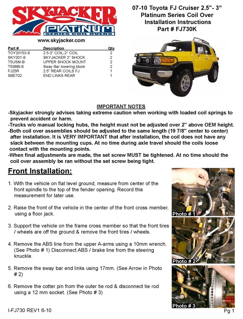
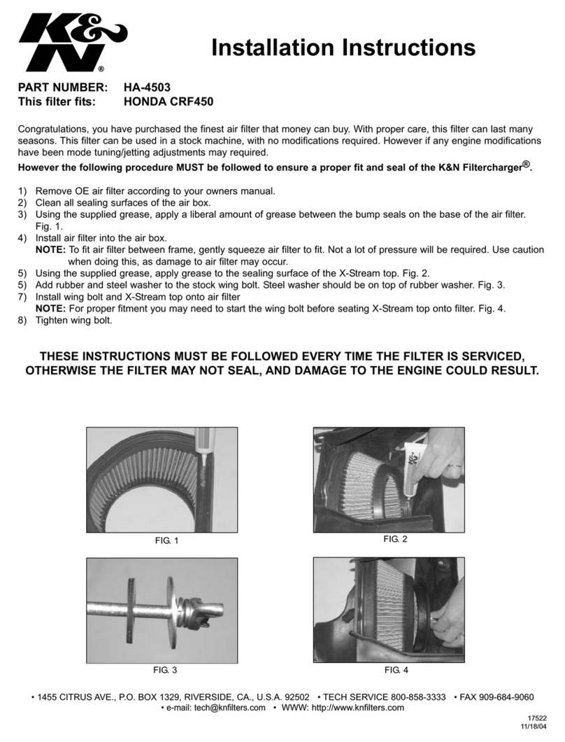
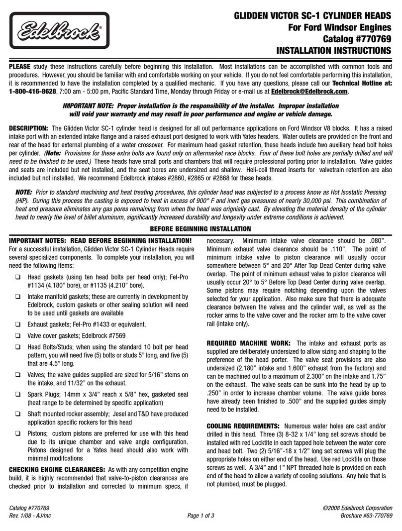
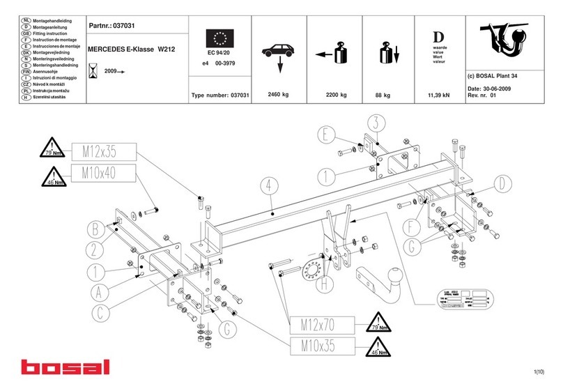
injen technology SP1126 User manual

Part Number SP1126
2011 BMW E82 135i E90 335i
(N55) L6 3.0L (turbo)
1- 2 piece TUNED air intake system
1- 3-1/2” web dry Nanofiber filter (#1021)
1- 3/16” ID x 1/2” long aluminum spacer (#10016)
2- 3” straight hose (#3044)
4- #048 clamps (#4004)
1- Power steering cup w/ bracket (#20088)
4- M4 button head screws (#6072)
3- M6 flange nuts (#6002)
(3 used on 135i)
(2 used on 335i)
1- M6 x 35mm stainless button head (#6007)
1- Fender washer (#6010)
1- Grommet (#8026)
1- Front mount air scoop (#6082)
4- M6 x 10mm stainless button head (#6083)
(4 used on 135i for scoops)
(4 used on 335i, 2 scoop & 2 Air scoop bracket)
1- Air scoop support bracket (335i only) (#20096)
1- Instruction (10 Pages)
Note: The C.A.R.B. Exempt sticker must be
attached under the hood in a manner that is
easily viewed by an emissions inspector.
Congratulations! You have just purchased the best engineered,
dyno-proven air intake system available.
Please check the contents of this box immediately.
Report any defective or missing parts to the Authorized Injen
Technology dealer you purchased this product from.
Before installing any parts of this system, please read the instructions
thoroughly. If you have any questions regarding installation please
contact the dealer you purchased this product from.
Installation DOES require some mechanical skills. A qualified
mechanic is always recommended.
*Do not attempt to install the intake system while the engine is hot.
The installation may require removal of radiator fluid line that may
be hot.
Injen Technology offers a limited lifetime warranty to the original
purchaser against defects in materials and workmanship. Warranty
claims must be handled through the dealer from which the item was
purchased.
Note: The installation of this air intake does require mechanical skills. Removal of the front bumper requires
loosening and removing several plastic plugs and screws that may be difficult. In addition to removing the
bumper, you may also have to remove the air resonator box, battery and tray when beginning this installation.
Injen strongly recommends that this system be installed by a professional mechanic.
MR Technology, “The World’s First Tuned air Intake System!”
Factory safe air/fuel ratio’s for Optimum performance Patent# 7,359,795
Figure 1 Figure 2
Note: The C.A.R.B Exempt sticker must be attached under the hood in a manner such that it is easily viewed by an emissions inspector.
This kit is equipped with the
Injen Ea nanofiber dry
filters, Ea nanofiber filters
do not require oil.
335i only

Pull back the 3 harness lines attached to the lower air
box assembly.
Lift and pull up the lower air box assembly from the 3
grommets attached to the engine and remove.
The air scoops removed as shown above.
Un-clip the 4 tabs holding in the upper half of airbox. Lift and remove the upper half of air box out of
vehicle.
Stock box shown in this picture Disconnect the MAF sensor.
Carefully pull up and remove the engine cover.
Loosen the clamp on intake tube using 7mm nut
driver.
For the 335i loosen and remove the 2 bolts and 2
plastic push clips holding in the primary 1 piece air
scoop using t25 torx bit.
Lift up and pull back the the lower primary air scoop
assembly.
Figure 3 Figure 4 Figure 5
Figure 6 Figure 7 Figure 8
Figure 9 Figure 10
Figure 12 Figure 13 Figure 14
Page 2 of Part# SP1126
For the 135i only loosen and remove the four bolts
holding the primary air scoops in place using t25 torx
bit.
135i 335i
Figure 11

Loosen the 2 remaining nuts holding in the bottom of
the bracket to the frame of vehicle. Pull harness away
from bracket.
Once removed, you should have completly removed
the power steering reservoir bracket and clamp from
vehicle.
Remove the reservoir clamp from vehicle.
With T30 torx bit, loosen the screw holding in intake
tube @ turbo housing.
Loosen the 2 nuts holding in the power steering
reservoir. Also, loosen the 10mm screw holding in
the bracket.
With 10mm socket and ratchet, loosen the bolt holding
in the intake tube on engine and remove.
Carefully pull back the crank case fitting from the
engine using a small flat head screwdriver.
Disconnect the crank case line harness.
Carefully lift intake tube and slide back towards fire-
wall and remove. Make sure you remove the rubber
gasket on turbo housing.
Carefully pull the clamp apart, and silde making the 2
lines pass the clamp.
Carefully lift and remove the bracket from the vehicle.
Figure 15 Figure 16 Figure 17
Figure 18 Figure 19 Figure 20
Figure 21 Figure 22 Figure 23
Figure 24 Figure 25 Figure 26
Page 3 of Part# SP1126
With 10mm ratchet and extension, loosen the screw
holding in the reservoir clamp.
135i

Page 4 of Part# SP1126
The Power steering reservoir bottle cup bracket and Injen power-scoop installed in the BMW 135i
Secure the passenger factory side scoop using the M6
button head screws and 2 flange nuts behind the core
support.
Tighten the 2 screws using allen key and secure.
Note: This does not require the use of the air scoop
bracket only, for the 335i.
Drill all the 4 holes out to 1/4” on the factory scoops
to make the M6 screws able to pass through.
The 3/16” aluminum spacer is slipped over the m6 x
35mm bolt used to secure the reservoir bracket.
The m6 flange nut is used to tighten the reservoir
bracket in place. Note: The 3/16” spacer between
the bracket and cross member, used to support the
bracket to keep it from distorting.
The stock m6 bolt is used to fasten the extended
bracket located on the new power steering cup.
Insert the m6 x 35mm bolt through the composite
cross member and through the 3/8” aluminum coupler
as shown in figure 26.
Applicable to the 135i only: Use a 1/4” drill bit to drill
a hole through the composite cross member, the
short bracket on the cup is used as a pattern.
The m6 x 35mm hex bolt is inserted through the
cross member, and into the 3/8” aluminum coupler.
The aluminum coupler is used as a back support for
the reservoir bracket as shown in figure 28.
Install the resovoir into the cup and secure. Note:
Make sure the resovoir bottle sits all the way down
and tight.
Install the driver side factory scoop, position the injen
power-scoop to the back of the core support, locate
the 2 inserts though the scoop. Secure the power-
scoop using the 2 remaining M6 button head screws.
Figure 27 Figure 28 Figure 29
Figure 30 Figure 31 Figure 32
Figure 33 Figure 34
Figure 36 Figure 37 Figure 38
A 10mm socket and ratchet is used to fasten the
flange nut to the m6 bolt.
Figure 35
Drilling required on the 135i Drilling required on the 135i

Page 5 of Part# SP1126
The Power steering reservoir bottle cup bracket and Injen power-scoop installed in the BMW 335i
Position the injen power-scoop to the back of the core
support, locate the 1 insert though the scoop. Secure
the power-scoop using the M6 button head screw.
Secure the plastic push clips to the factory scoop.
Position the bracket to the power steering resovoir
bracket thredded insert. Secure using the remaining
M6 button head screw and tighten. This will allow for
support of the power-scoop. (NOTE: you should
have 1 remaining flange nut, please discard)
Install the factory scoop, secure the passenger side
using the M6 button head screw and flange nut
behind the core support.
Make sure the spacer is used to preventing the brack-
et to distort. Tighten using allen key till bottoms out.
Install the resovoir into the cup and secure. Note:
Make sure the resovoir bottle sits all the way down
and tight.
The stock m6 bolt is used to fasten the extended
bracket located on the new power steering cup.
Install the M6x35mm bolt through bracket, now install
the spacer to the bolt. Position the bolt to the back
side of the thredded insert from previous step.
A) Loosen the bolt on left side of core support hold-
ing in headlight using T30 torx bit. B) Remove the
bolt from vehicle.
Use provided flange nut and secure the bolt. Tighten
using 10mm socket and ratchet.
Drill both holes out to 1/4” on the factory scoop to
make the M6 screws able to pass through.
Install the Air scoop bracket to the power-scoop.
secure using M6 button head screw.
Figure 39 Figure 40 Figure 41
Figure 42 Figure 43 Figure 44
Figure 45 Figure 46
Figure 48 Figure 49 Figure 50
Install the injen power-scoop only to see how you
will only be able to line up the 1 hole closes to the
power steering resovoir bracket.
Remove the screw.
Figure 47
A
B

Page 6 of Part# SP1126
135i power-scoop and resovoir bracket shown above.
With clamps provided, install the 3” straight hose to the turbo housing. Secure the clamp on the turbo housing only using 8mm nut driver.
335i power-scoop and resovoir/air scoop bracket shown above. Note:
Remaining steps will be the same for both the 135i and 335i.
With t30 torx bit, loosen the 2 screws holding in the crank case line.
Carefully pull out and remove.
Install into the new lower assembly intake tube. Secure using the M4 but-
ton head screws provided.
Position the lower intake tube assembly into vehicle. Note: Very tight fit,
position from firewall forward to the hose from step 56.
Position the tube and make sure it fits secure. Do not tighten.
Figure 51 Figure 52
Figure 53 Figure 54
Figure 55 Figure 56
Figure 57 Figure 58
135i
335i

Connect the crank case line on the engine side. From step 15, use the factory bolt and provided fender washer to secure
the bracket on engine. Note: Make sure you use the fender washer.
Connect the Crank case line harness.
A) With t30 torx bit, loosen the 2 screws holding in the MAF sensor.
B) Remove the MAF sensor.
Install the 3” straight hose with clamps provided and attach to the end of
the intake tube. Tighten on the tube only.
A) Install the MAF sensor into the new intake tube. B) Secure the MAF
sensor using the provided M4 button head screws.
A) Attach the grommet to the hole on the bracket. B) Install the upper
intake tube assembly into the vehicle and position to the tube and factory
airbox engine fitting.
Figure 59 Figure 60
Figure 63
Figure 62
Figure 61
Figure 64
Secure the bracket and slide the slot on bracket forward so it stops and
tighten using 10mm socket and ratchet.
335i
Figure 65 Figure 66
Page 7 of Part# SP1126
(B)
(A)
(A)
(B)
(B)
(A)

Make sure that the grommet is installed and seated properly as shown in
above photo.
Install air filter to the tube and tighten and secure.
Figure 67 Figure 68
Position for BEST POSSIBLE FIT. Note: This may need a lot of
adjustment with both tubes. Make sure that the hood has clearance
and the tube is not touching the fuel line below.
Tighten all clamps using 8mm nut driver.
Re-install the engine cover.
135i install shown above. Adjust if necessary to have clearance.
Page 8 of Part# SP1126
335i install shown above. Adjust if necessary to have clearance.
Figure 71
Figure 70
Figure 69
Figure 72
1. Upon completion of the installation, reconnect the negative battery terminal before you start the engine.
2. Align the entire intake system for the best possible fit. Once the intake has been properly fitted continue
to tighten all nuts, bolts and clamps.
3. Periodically, recheck the alignment of the intake system and make sure there is proper clearance around
and along the length of the intake. Failure to follow proper maintenance procedures may cause
damage to the intake and will void the warranty.
4. Start the engine and listen carefully for any odd noises, rattles and/or air leaks prior to taking it for a test
drive. If any problems arise go back and check the vacuum lines, hoses and clamps that maybe causing
leaks or rattles and correct the problem.
5.
Check the filter for excessive dirt build up.
Congratulations! You have just completed the installation of the best intake system sold on the market.
Enjoy the added power and performance of your new intake system.
Other injen technology Automobile Part manuals
injen technology
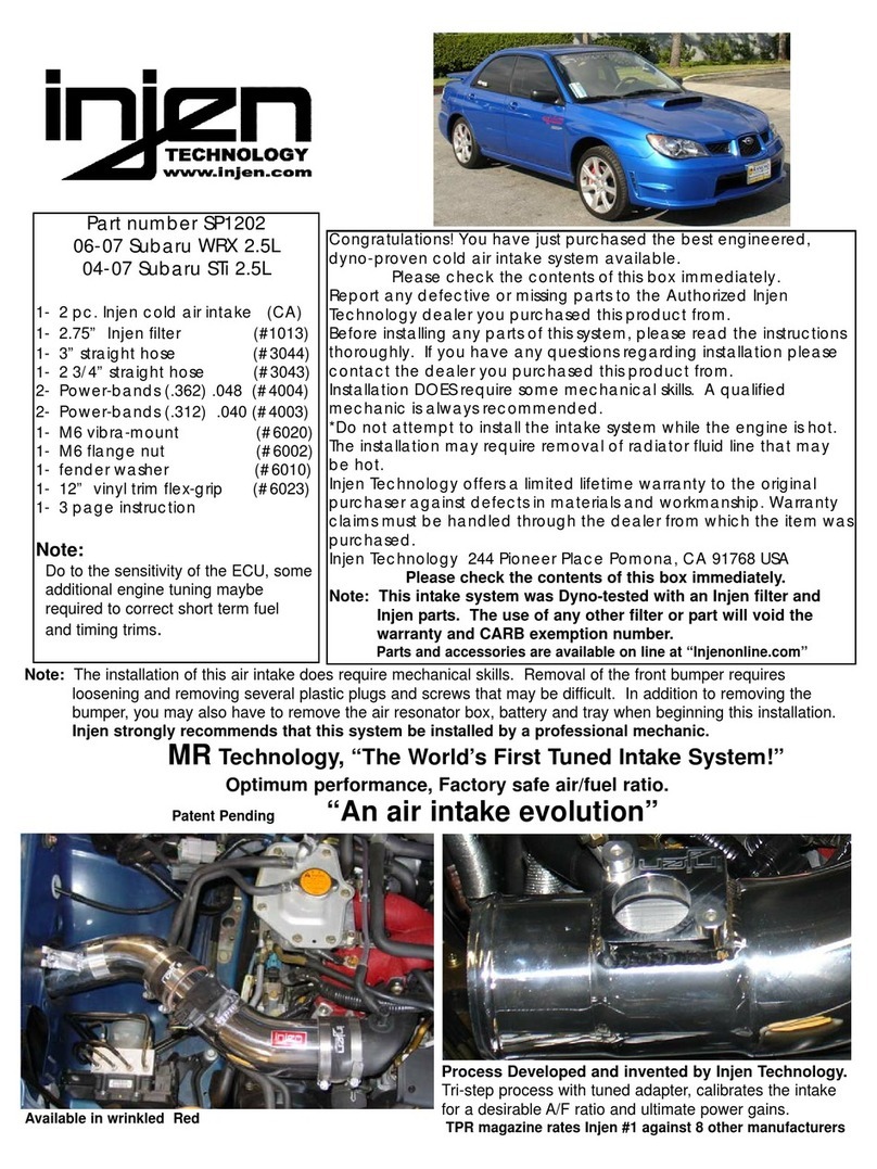
injen technology SP1202 User manual

injen technology
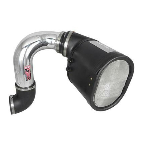
injen technology SP1360 User manual

injen technology
injen technology SP2106 User manual

injen technology
injen technology RD6061 User manual
injen technology
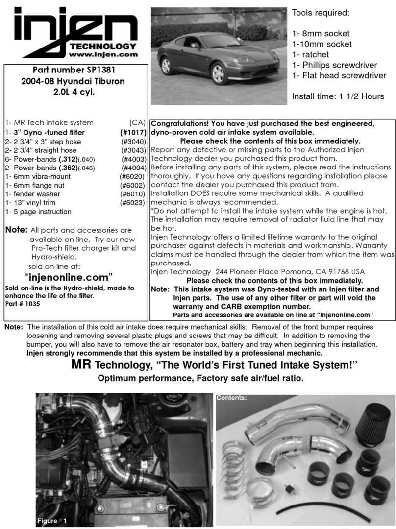
injen technology SP1381 User manual

injen technology
injen technology PF8075 User manual
injen technology
injen technology SP1567 User manual