manuals.online logo
Brands
  1. Home
  2. •
  3. Brands
  4. •
  5. injen technology
  6. •
  7. Automobile Part
  8. •
  9. injen technology SP1360 User manual

injen technology SP1360 User manual

Part number SP1360
2012 Hyundai Elantra
1.8L 4cyl.
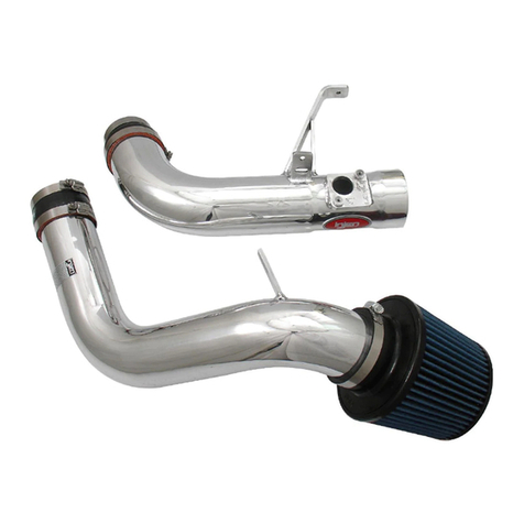
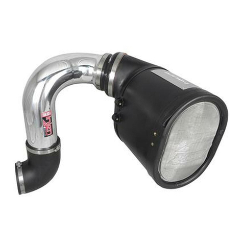
1- 2 piece SP™ Intake system
1- 3” Web/Nano Fiber dry filter (#1020)
1- 3” straight hose (#3044)
1- 2-3/4”straight hose (#3043)
2- Power-Band .048 (#4004)
2- Power-Band .040 (#4003)
1- M6 vibra-mount (#6020)
1- M6 flange nut (#6002)
1- Fender washer (#6010)
1- 4 page instruction
Note: All parts and accessories are sold
on-line a “injenonline.com”
Note: The C.A.R.B. Exempt sticker must be attached
under the hood in a manner such that it is easily viewed by
an emissions inspector.
Congratulations! You have just purchased the best engineered,
dyno-proven air intake system available.
Please check the contents of this box immediately.
Report any defective or missing parts to the Authorized Injen
Technology dealer you purchased this product from.
Before installing any parts of this system, please read the instructions
thoroughly. If you have any questions regarding installation please
contact the dealer you purchased this product from.
Installation DOES require some mechanical skills. A qualified
mechanic is always recommended.
*Do not attempt to install the intake system while the engine is hot.
The installation may require removal of radiator fluid line that may
be hot.
Injen Technology offers a limited lifetime warranty to the original
purchaser against defects in materials and workmanship. Warranty
claims must be handled through the dealer from which the item was
purchased.
Injen Technology 244 Pioneer Place Pomona, CA 91768 USA
Please check the contents of this box immediately.
Note: This intake system was Dyno-tested with an Injen filter and
Injen parts the use of any other filter or part will void the
warranty and CARB exemption number.
Parts and accessories are available on line at “Injenonline.com”
Note: The installation of this cold air intake does require mechanical skills. Removal of the front bumper requires
loosening and removing several plastic plugs and screws that may be difficult. It is recommended that this
system be installed by a professional mechanic. Be sure to disconnect the negative terminal before proceeding.
Congratulations! You have just purchased the worlds first tuned intake system.
MR Technology, Leading the way!
“The Worlds First Tuned Air Intake System”™
Figure 1 Figure 2
With 10mm socket and ratchet loosen the 3 screws
holding in the air box assembly.
Now lift up and remove the stock intake assembly
from the vehicle.
Stock OEM intake system. Now with a 10mm nut driver loosen the clamp on the
throttle body.
Now with pliers, loosen the clamp holding in crank
case line and pull back.
Now carefully pull back the intake hose from the
throttle body.
Remove the 2 push clips from the front of the radiator
support holding in the ram scoop and remove.
Carefully remove the front bumper cover, using flat
head screwdriver and 8mm socket, carefully pull from
corners out. Disconnect fog light harness. Search web
for more info on removal of front bumper cover.
A)With 10mm wrench, loosen the screw holding in the
stock airbox resonator inside the engine compartment.
B)Loosen the 2 screws on the other side holding in
the resonator and remove.
Pull any lines that are attached or on the resonator
and remove from the vehicle.
Install the vibra mount to thredded insert closes to the
headlight. Secure the vibra mount and tighten.
Install the 2-3/4” straight hose to the throttle body and
secure using clamps provided and tighten on the
throttle body only.
Figure 4
Figure 3 Figure 5
Figure 6 Figure 7 Figure 8
Figure 9 Figure 10 Figure 11
Figure 12 Figure 13 Figure 14
Page 2 of Part# SP1360
A
B
Now tighten the nut using 10mm socket and
extension. Secure using the factory clamp. Re-install bumper
cover and connect battery terminals.
Using long flathead or 8mm nut driver, tighten the
clamp and secure.
Install the lower intake assembly and position to the
vibra mount and to the straight hose. Do Not Tighten. Install the filter to the intake tube.
Install the upper intake tube assembly into the vehicle
and position. Do Not Tighten.
Tighten the clamp only on the intake tube side using
8mm nut driver.
Install the 3” straight hose to the upper intake
assembly.
Now secure the bracket using provided M6 washer
and nut.
Position for best fit and tighten the remaining clamp
using 8mm nut driver.
Position for best fit and tighten the remaining clamp
on the throttle body using 8mm nut driver.
Now secure the crank case line to the fitting on the
intake tube.
Figure 15 Figure 16 Figure 17
Figure 19
Figure 18 Figure 20
Figure 23
Figure 22
Figure 21
Figure 26
Figure 25Figure 24
Page 3 of Part# SP1360
Check the entire air intake system for best possible fit, once proper clearance
has been made through out the length of the intake, continue to tighten all
nuts, bolts and clamps. Short Ram image shown above.
Congratulations! You have just completed the installation of the World’s first
tuned intake system, the Power-Flow intake, featuring MR Technology.
Periodically, check the system for fitment, this will enhance the life of your
Power-Flow system, failure to do so will void the warranty.
Page 4 of Part# SP1360
1. Upon completion of the installation, reconnect the negative battery terminal before you start the engine.
2. Align the entire intake system for the best possible fit. Once the intake has been properly fitted continue
to tighten all nuts, bolts and clamps.
3. Periodically, recheck the alignment of the intake system and make sure there is proper clearance around
and along the length of the intake. Failure to follow proper maintenance procedures may cause
damage to the intake and will void the warranty.
4. Start the engine and listen carefully for any odd noises, rattles and/or air leaks prior to taking it for a test
drive. If any problems arise go back and check the vacuum lines, hoses and clamps that maybe causing
leaks or rattles and correct the problem.
5. Check the filter for excessive dirt build up. Clean or replace the filter with an original Injen filter (can be
bought on-line at “injenonline.com”). Congratulations! You have just completed the installation of the
best intake system sold on the market. Enjoy the added power and performance of your new intake
system.

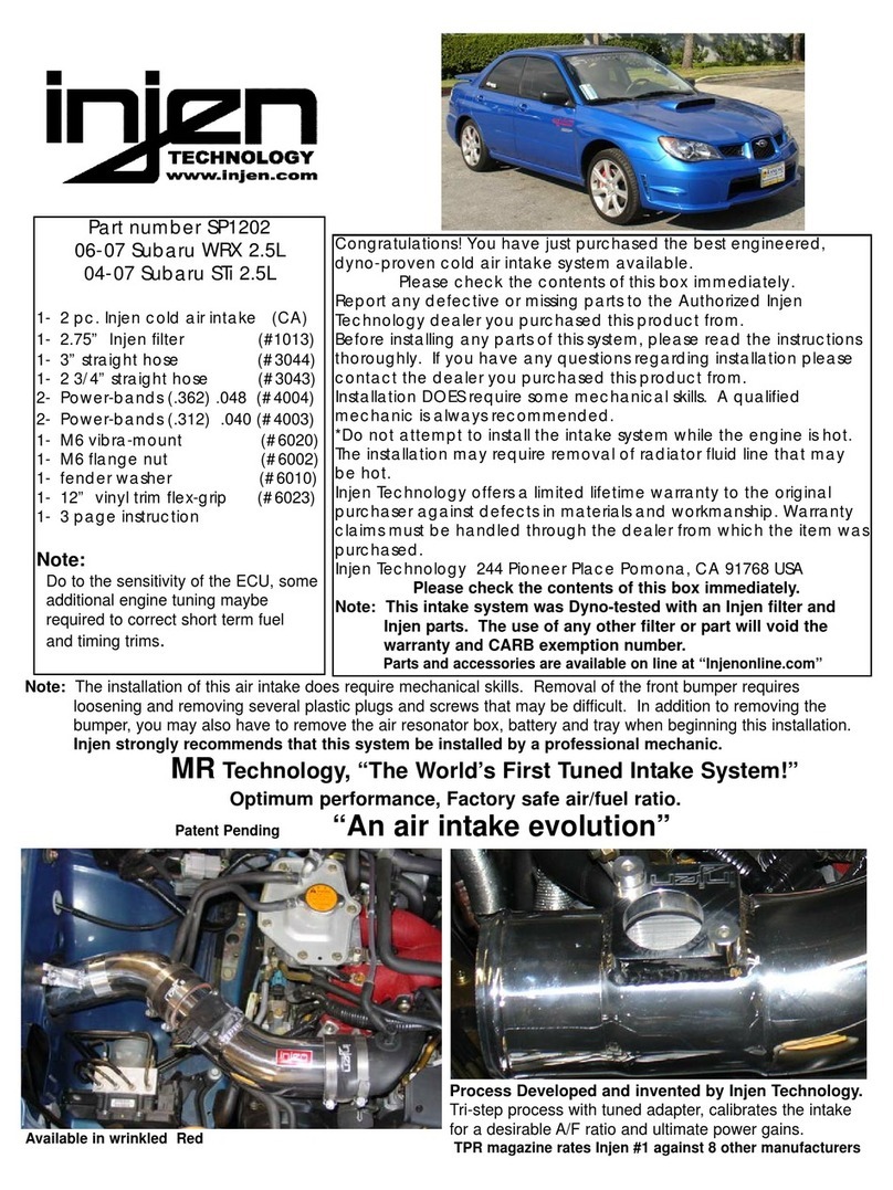
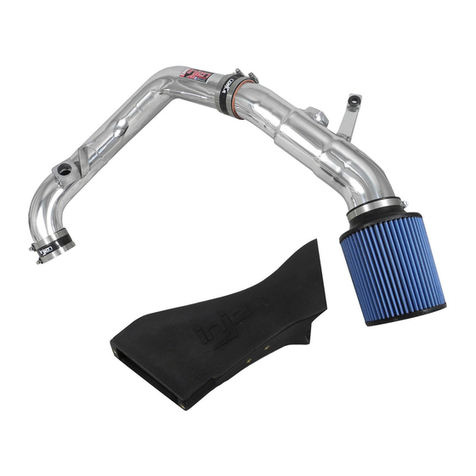
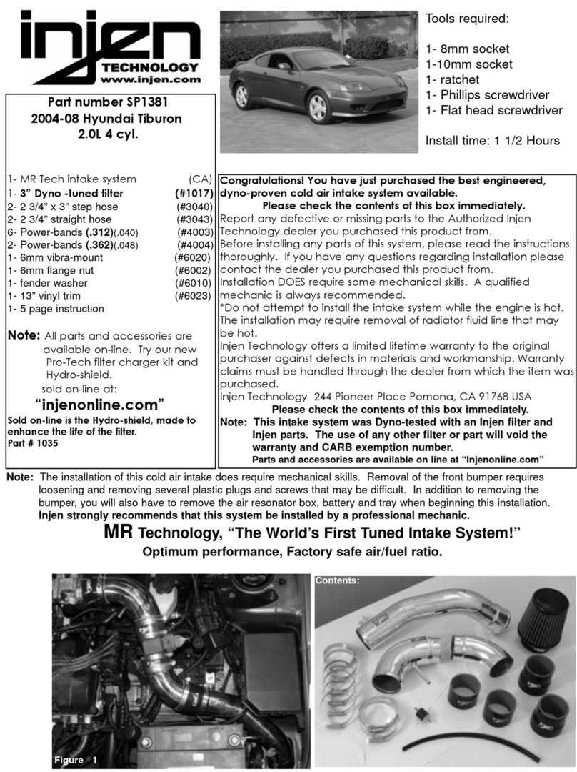
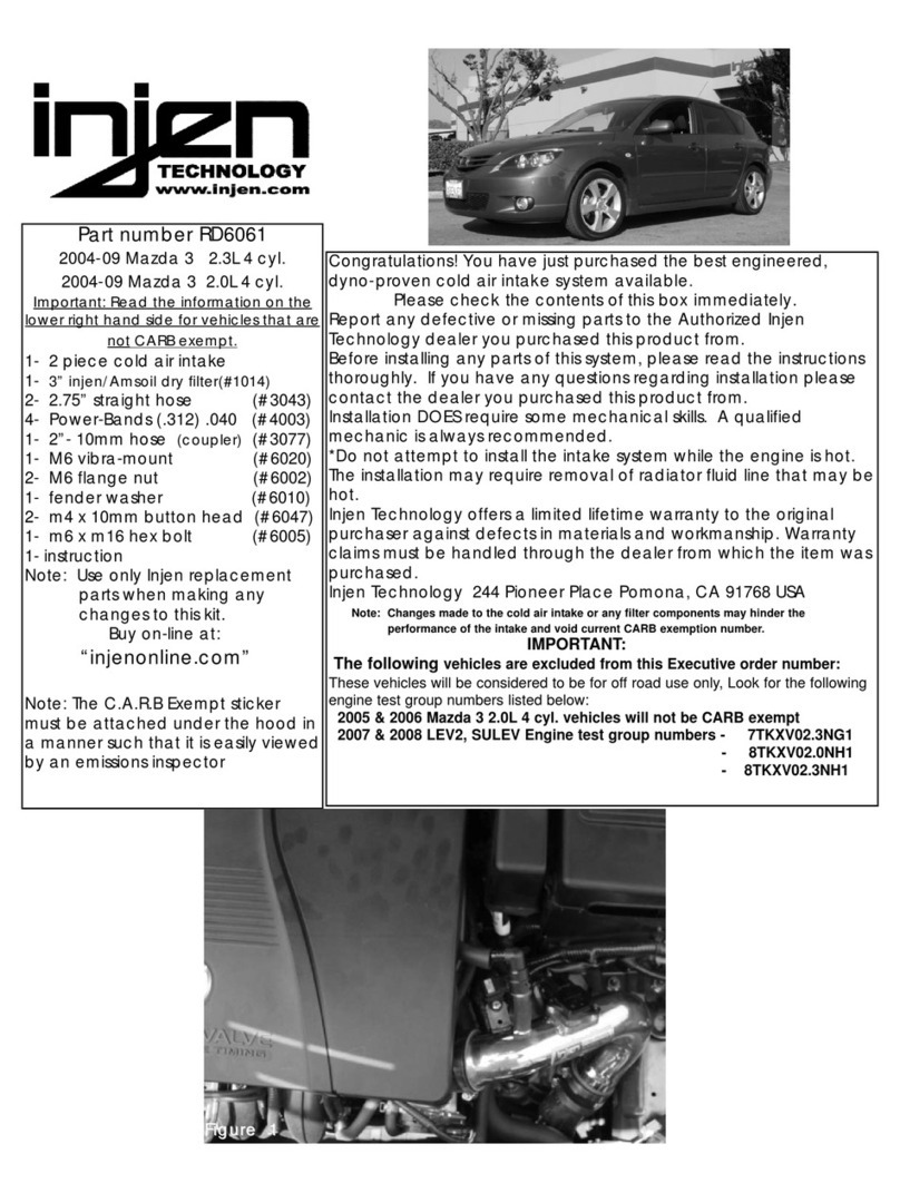
Other injen technology Automobile Part manuals

injen technology PF8075 User manual

injen technology

injen technology PF8075 User manual

injen technology SP1202 User manual

injen technology

injen technology SP1202 User manual

injen technology SP1126 User manual

injen technology

injen technology SP1126 User manual

injen technology SP1381 User manual

injen technology

injen technology SP1381 User manual

injen technology RD6061 User manual

injen technology

injen technology RD6061 User manual

injen technology SP2106 User manual

injen technology

injen technology SP2106 User manual

injen technology SP1567 User manual

injen technology

injen technology SP1567 User manual

Popular Automobile Part manuals by other brands

Parker VO40 technical information

Parker

Parker VO40 technical information

Edelbrock 2281 Specifications

Edelbrock

Edelbrock 2281 Specifications

Skyjacker FJ730K installation instructions

Skyjacker

Skyjacker FJ730K installation instructions

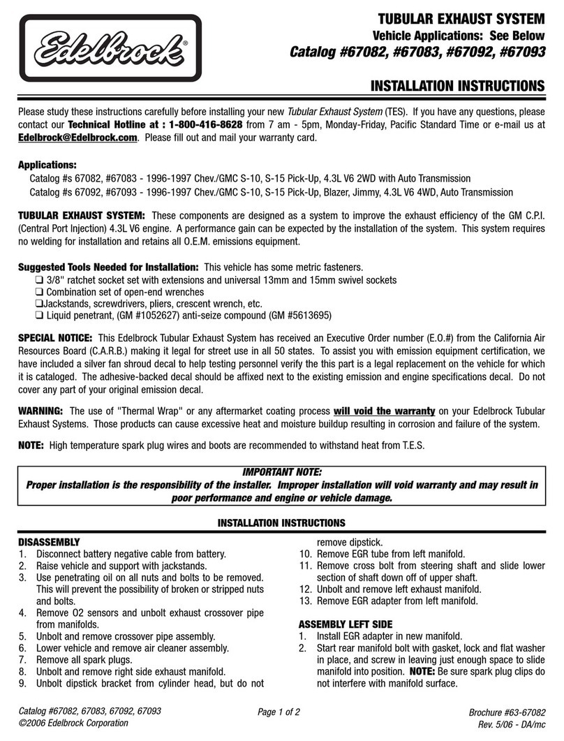
Edelbrock 67082 installation instructions

Edelbrock

Edelbrock 67082 installation instructions

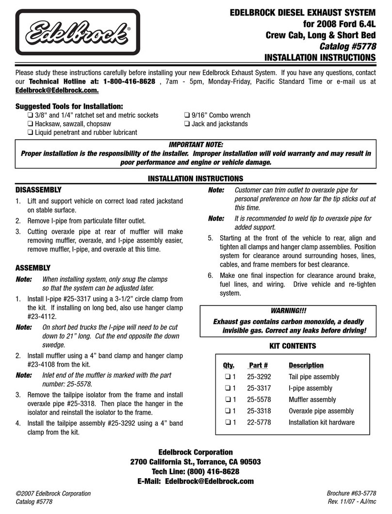
Edelbrock 5778 installation instructions

Edelbrock

Edelbrock 5778 installation instructions

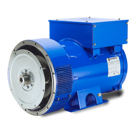
MarelliMotori MJB 250 Operation and maintenance manual

MarelliMotori

MarelliMotori MJB 250 Operation and maintenance manual

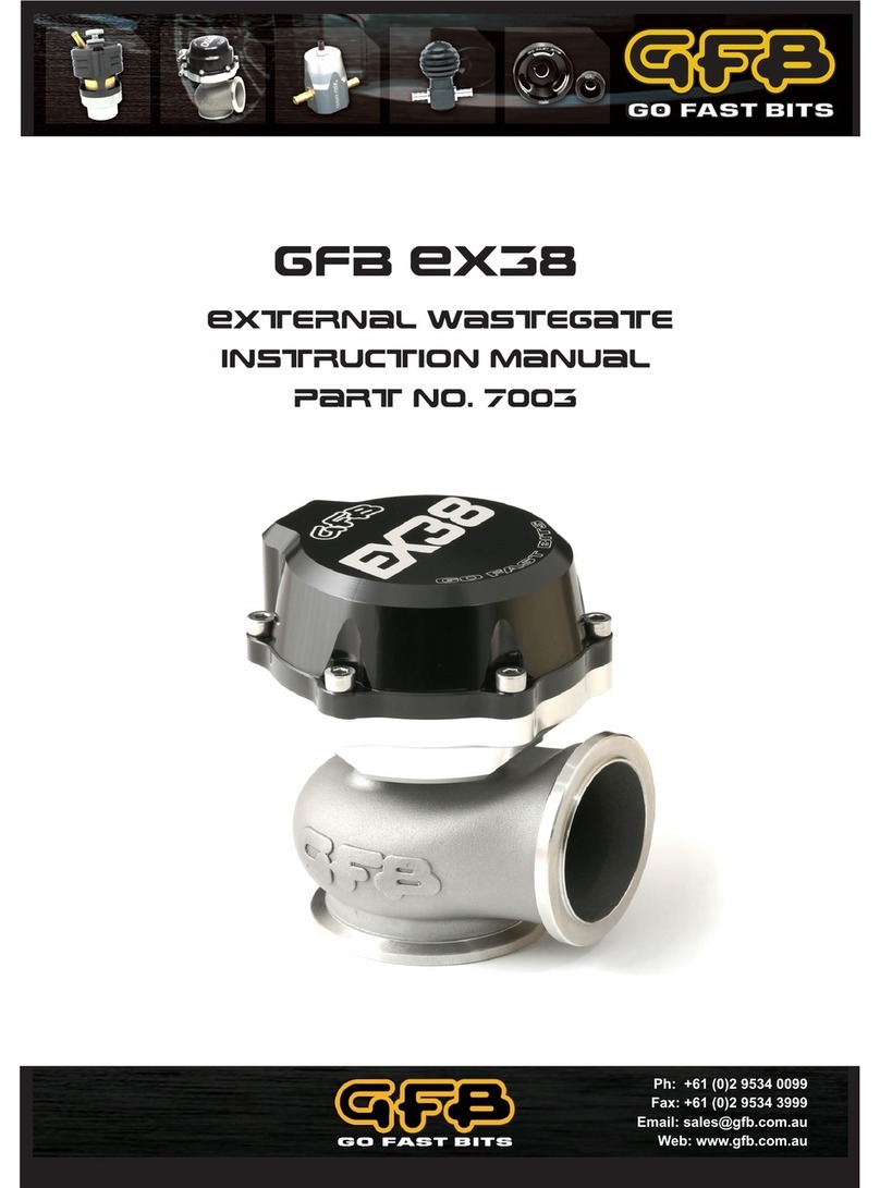
GFB EX38 instruction manual

GFB

GFB EX38 instruction manual

Edelbrock 72700 installation instructions

Edelbrock

Edelbrock 72700 installation instructions

Edelbrock 90 V6 200 installation instructions

Edelbrock

Edelbrock 90 V6 200 installation instructions

Munters MWI Series Quick assembly guide

Munters

Munters MWI Series Quick assembly guide

Edelbrock 70024 installation instructions

Edelbrock

Edelbrock 70024 installation instructions

Edelbrock 1727 installation instructions

Edelbrock

Edelbrock 1727 installation instructions

ATS OPL028 user manual

ATS

ATS OPL028 user manual

Edelbrock 2166 installation instructions

Edelbrock

Edelbrock 2166 installation instructions

Mitsubishi F5MR1 Workshop manual

Mitsubishi

Mitsubishi F5MR1 Workshop manual

Johnson Controls VA-8051 specification

Johnson Controls

Johnson Controls VA-8051 specification

Edelbrock 1565 installation instructions

Edelbrock

Edelbrock 1565 installation instructions

DYNATEK DP4000-HD2 User instructions

DYNATEK

DYNATEK DP4000-HD2 User instructions

manuals.online logo
manuals.online logoBrands
  • About & Mission
  • Contact us
  • Privacy Policy
  • Terms and Conditions

Copyright 2025 Manuals.Online. All Rights Reserved.