manuals.online logo
Brands
  1. Home
  2. •
  3. Brands
  4. •
  5. injen technology
  6. •
  7. Automobile Part
  8. •
  9. injen technology SP1381 User manual

injen technology SP1381 User manual

!"#$%&'()*#%+!,-.,
/00120.%34'&5"6%76)'#8&%%%%%%%%%%
/90:%1%;4<9
!"#$%#&'()#*+,-.'#/0/,'1################2345
!"#-=%>4&8%2$'&*5%?6<$*#%%%%%%%%%%%%%%%%@A,0,BC
2- 2 3/4” x 3” step hose (#3040)
2- 2 3/4” straight hose (#3043)
6- Power-bands (.312)(.040) (#4003)
2- Power-bands (.362)(.048) (#4004)
1- 6mm vibra-mount (#6020)
1- 6mm flange nut (#6002)
1- fender washer (#6010)
1- 13” vinyl trim (#6023)
1- 5 page instruction
D8$*E 466#7-8,/#-+9#-(('//:8*'/#-8'
-;-*6-<6'#:+"6*+'=##&80#:>8#+'?
@8:"&'()#A*6,'8#()-8B'8#.*,#-+9
C098:"/)*'69=
/:69#:+"6*+'#-,D
F6&G*&8&<6&*9;8(=
+8<5%8&2<6&*%6H%$I*%345#82HI6*<5J%("5*%$8%
*&I"&;*%$I*%<6?*%8?%$I*%?6<$*#9
!"#$%A%,0-K
L8&M#"$'<"$68&HN%O8'%I"P*%G'H$%Q'#;I"H*5%$I*%)*H$%*&M6&**#*5J
54&82Q#8P*&%;8<5%"6#%6&$"R*%H4H$*(%"P"6<")<*9
!<*"H*%;I*;R%$I*%;8&$*&$H%8?%$I6H%)8S%6((*56"$*<49
%'7:8,#-+0#9'A'(,*;'#:8#1*//*+B#7-8,/#,:#,)'#4>,):8*E'9#F+G'+#
&'()+:6:B0#9'-6'8#0:>#7>8()-/'9#,)*/#78:9>(,#A8:1=
H'A:8'#*+/,-66*+B#-+0#7-8,/#:A#,)*/#/0/,'1I#76'-/'#8'-9#,)'#*+/,8>(,*:+/
,):8:>B)60=##FA#0:>#)-;'#-+0#J>'/,*:+/#8'B-89*+B#*+/,-66-,*:+#76'-/'
(:+,-(,#,)'#9'-6'8#0:>#7>8()-/'9#,)*/#78:9>(,#A8:1=
F+/,-66-,*:+#KLMN#8'J>*8'#/:1'#1'()-+*(-6#/.*66/=##4#J>-6*A*'9
1'()-+*(#*/#-6?-0/#8'(:11'+9'9=
OK:#+:,#-,,'17,#,:#*+/,-66#,)'#*+,-.'#/0/,'1#?)*6'#,)'#'+B*+'#*/#):,=
&)'#*+/,-66-,*:+#1-0#8'J>*8'#8'1:;-6#:A#8-9*-,:8#A6>*9#6*+'#,)-,#1-0
<'#):,=
F+G'+#&'()+:6:B0#:AA'8/#-#6*1*,'9#6*A',*1'#?-88-+,0#,:#,)'#:8*B*+-6
7>8()-/'8#-B-*+/,#9'A'(,/#*+#1-,'8*-6/#-+9#?:8.1-+/)*7=#P-88-+,0
(6-*1/#1>/,#<'#)-+96'9#,)8:>B)#,)'#9'-6'8#A8:1#?)*()#,)'#*,'1#?-/
7>8()-/'9=##
F+G'+#&'()+:6:B0##QRR#@*:+''8#@6-('#@:1:+-I#34#S!TUV#WN4
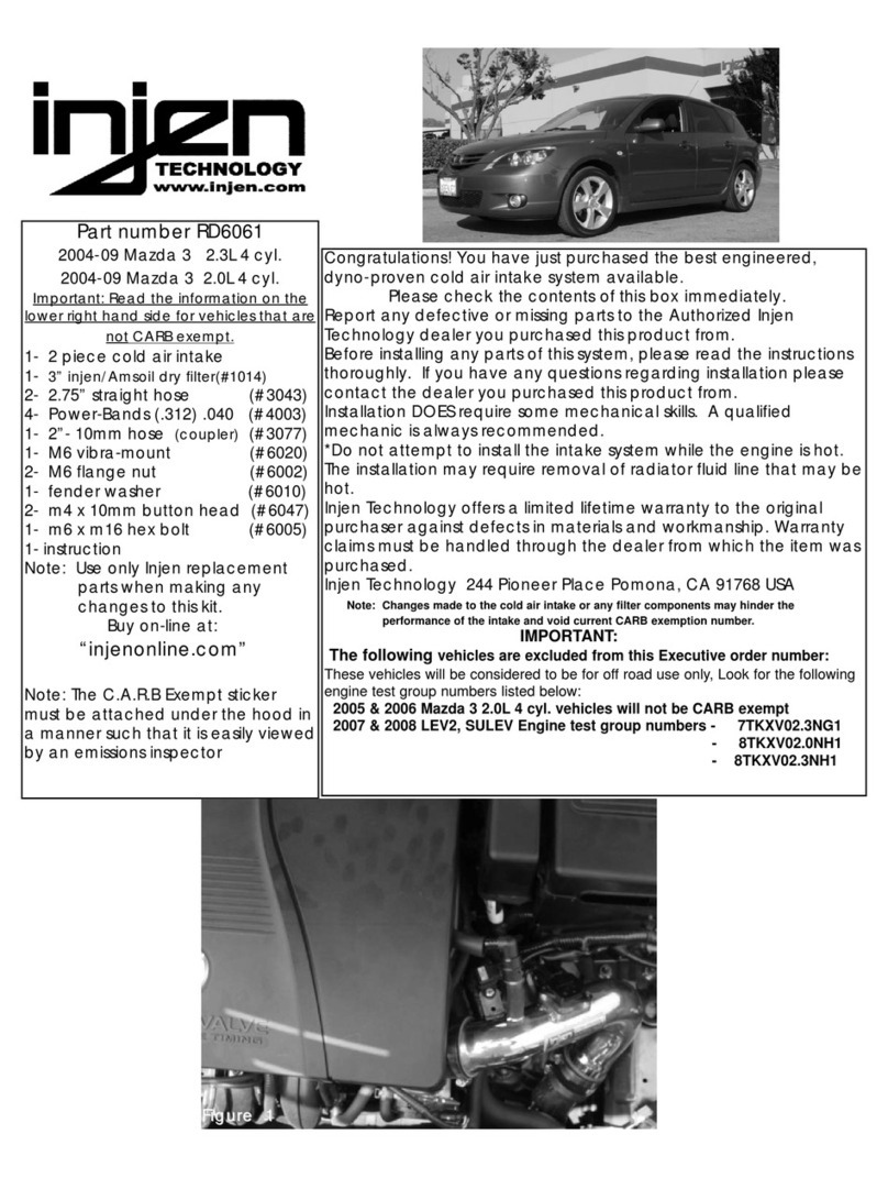
Please check the contents of this box immediately.
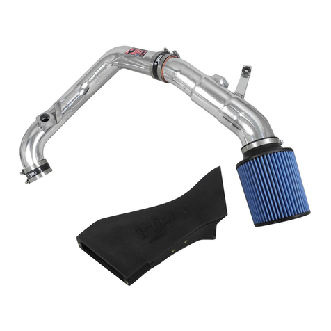
Note: This intake system was Dyno-tested with an Injen filter and
Injen parts. The use of any other filter or part will void the
warranty and CARB exemption number.
Parts and accessories are available on line at “Injenonline.com”
Note: The installation of this cold air intake does require mechanical skills. Removal of the front bumper requires
loosening and removing several plastic plugs and screws that may be difficult. In addition to removing the
bumper, you will also have to remove the air resonator box, battery and tray when beginning this installation.
Injen strongly recommends that this system be installed by a professional mechanic.
MR Technology, “The World’s First Tuned Intake System!”
Optimum performance, Factory safe air/fuel ratio.
Tools required:
1- 8mm socket
1-10mm socket
1- ratchet
1- Phillips screwdriver
1- Flat head screwdriver
Install time: 1 1/2 Hours
Figure 1
Contents:
Remove the battery cables from the battery post and
remove the battery the from the engine compartment.
Disconnect air box cleaner from the air intake duct
and lift the air box out of the engine compartment.
Depress end clips on the electrical harness clip and
pull the clip away from the mass air flow sensor.
Press the step hose over the throttle body and use two
power bands on the hose, tighten the band on the
throttle body side for now.
Loosen clamps that secures the air intake duct to the
throttle body (A) and the air box cleaner to the lower
air intake duct (B).
Loosen clamp that secures the air duct over the mass
air flow sensor. Disconnect and remove the mass air
flow sensor from the air duct as shown above.
The tabs with the holes are used to hook into the
notch located in the resonator box as shown above.
The head lamp is now pulled out of the frame and the
harness clip is disconnected from the rear of the head
lamp.
Remove top clips from lower air box (A) Once clips
have been removed, lift the top cover and remove the
inside panel filter. Loosen and remove the three bolts
on the lower air box fastened to the motor mount (B).
Once the air box has been removed, continue to
remove the air intake duct from the throttle body.
Remove the m6 bolt located on the corner battery
tray. Once you have removed the bolt, gently pry the
top resonator box loose.
Remove the two bolts from the tabs on the head
lamp. Once bolts have been removed, continue to
pull the head lamp out of the frame.
Page 2 of Part# SP1381
Figure 2 Figure 3 Figure 4
Figure 5 Figure 6 Figure 7
Figure 8 Figure 9 Figure 10
Figure 11Figure 12 Figure 13
(A)
(A)
(A)
(B)
>>>
>>>
(A)
(B)
>>>
>>>
>>>
>>>
The plastic plug is removed from the upper tab, then
the resonator is gently pulled out of the resonator
opening.
The vibra-mount is screwed into the pre-tapped brace
on the engine mount.
Screw the vibra-mount into the brace until it sits flush
over the engine mount.
The driver side bumper is pulled away and the res-
onator box is removed from the inside corner.
The air resonator box is now removed from the lower
corner.
The primary intake is now pressed into the step hose
located on the throttle body.
The primary intake is aligned for a perfect fit. The straight hose is placed over the mass air flow sen-
sor. Two power bands are placed over the hose on the
mass air plow sensor and the power bands to the inside
of the mass air flow sensor are tightened.
The resonator elbow is pulled out and no longer
used for this installation.
Disconnect and remove the top plastic clips located
on the top bumper end. Peel the driver side bumper
bumper away and remove the air box cleaner.
The 13” vinyls trim is pressed over the resonator
opening s shown above.
The vacuum line is now placed over the intake port.
Page 3 of Part# SP1381
Figure 14 Figure 15 Figure 16
Figure 17 Figure 18 Figure 19
Figure 20 Figure 21 Figure 22
Figure 23 Figure 24 Figure 25
>>>
>>>
>>>
>>>
>>>
>>>
Insert directional mass air flow sensor over the
primary intake until they both have butted up against
each other.
The intake is aligned to the vibra-mount stud located
on the engine mount.
Peel the driver side bumper back and insert the top
section of the third intake into the resonator opening
as shown above.
The intake is inserted into the resonator opening and slipped into the engine
compartment with the intake bracket facing up.
The 3' step hose is pressed over the secondary
intake and two power bands are used, tighten the
power band on the intake side for now.
Align the mass air flow sensor so that the harness
connection is facing the driver side firewall. Do not
over tighten the power bands at this point.
The intake is now fully inserted into the engine compartment by way of the res-
onator opening.
The third intake is aligned and pressed into the end of the step hose. While
pressing the intake into the hose, adjust and align the intake bracket to the vibra-
mount stud.
The intake bracket is aligned to the vibra-mount stud and the m6 flange nut and
fender washer are used to fasten the intakes together.
Page 4 of Part# SP1381
Figure 26 Figure 27 Figure 28
Figure 29 Figure 30
Figure 31 Figure 32
Figure 34 Figure 35
>>>
>>>
>>>
>>>
>>>
The secondary intake is now pressed into the hose
located on the mass air flow sensor as shown above.
Figure 33
>>>
>>>
>>>
,9 W7:+#(:176',*:+#:A#,)'#*+/,-66-,*:+I#8'(:++'(,#,)'#+'B-,*;'#<-,,'80#,'81*+-6#<'A:8'#0:>#/,-8,#,)'#'+B*+'=##
/9 46*B+#,)'#'+,*8'#*+,-.'#/0/,'1#A:8#,)'#<'/,#7://*<6'#A*,=##L+('#,)'#*+,-.'#)-/#<''+#78:7'860#A*,,'9#(:+,*+>'
,:#,*B),'+#-66#+>,/I#<:6,/#-+9#(6-17/=
-9 @'8*:9*(-660I#8'()'(.#,)'#-6*B+1'+,#:A#,)'#*+,-.'#/0/,'1#-+9#1-.'#/>8'#,)'8'#*/#78:7'8#(6'-8-+('#-8:>+9
-+9#-6:+B#,)'#6'+B,)#:A#,)'#*+,-.'=##X-*6>8'#,:#A:66:?#78:7'8#1-*+,'+-+('#78:('9>8'/#1-0#(->/'
9-1-B'#,:#,)'#*+,-.'#-+9#?*66#;:*9#,)'#?-88-+,0=
19 N,-8,#,)'#'+B*+'#-+9#6*/,'+#(-8'A>660#A:8#-+0#:99#+:*/'/I#8-,,6'/#-+9Y:8#-*8#6'-./#78*:8#,:#,-.*+B#*,#A:8#-#,'/,
98*;'=##FA#-+0#78:<6'1/#-8*/'#B:#<-(.#-+9#()'(.#,)'#;-(>>1#6*+'/I#):/'/#-+9#(6-17/#,)-,#1-0<'#(->/*+B
6'-./#:8#8-,,6'/#-+9#(:88'(,#,)'#78:<6'1=
K9 3)'(.#,)'#A*6,'8#A:8#'Z('//*;'#9*8,#<>*69#>7=##36'-+#:8#8'76-('#,)'#A*6,'8#?*,)#-+#:8*B*+-6#F+G'+#A*6,'8#2(-+#<'#
<:>B),#:+"6*+'#-,#[*+G'+:+6*+'=(:1\5=##3:+B8-,>6-,*:+/]##^:>#)-;'#G>/,#(:176','9#,)'#*+/,-66-,*:+#:A#,)'#<'/,##
*+,-.'#/0/,'1#/:69#:+#,)'#1-8.',=####M+G:0#,)'#-99'9#7:?'8#-+9#7'8A:81-+('#:A#0:>8#+'?#*+,-.'#/0/,'1=
Here is a top shot of the secondary and third intakes butted together and the
intake bracket is aligned to the vibra-mount stud.
The electrical harness clip is pressed over the mass air flow sensor until you
have heard the two snap in together.
The bumper corner is peeled back once again and the filter is pressed over the
intake end. Once the intake end has butted up against the filter stops, continue
to fasten the filter neck clamp.
The battery is now placed back into its original location as shown above.
The head light is now inserted into the lamp frame and fastened with the two
stock screws. The bumper plugs and clips are reused to secure the entire
bumper to the frame.
Congratulations! You have now completed the installation of this intake system.
Periodically, we urge you to check the fitment of this intake system to prevent
any damage because of possible shifting of the intake system.
Page 5 of Part# SP1381
Figure 36 Figure 37
Figure 38 Figure 39
Figure 40 Figure 41

Other injen technology Automobile Part manuals

injen technology SP2106 User manual

injen technology

injen technology SP2106 User manual

injen technology SP1360 User manual

injen technology

injen technology SP1360 User manual

injen technology SP1126 User manual

injen technology

injen technology SP1126 User manual

injen technology PF8075 User manual

injen technology

injen technology PF8075 User manual

injen technology RD6061 User manual

injen technology

injen technology RD6061 User manual

injen technology SP1567 User manual

injen technology

injen technology SP1567 User manual

injen technology SP1202 User manual

injen technology

injen technology SP1202 User manual

Popular Automobile Part manuals by other brands

Active E36 installation instructions

Active

Active E36 installation instructions

Edelbrock 5266 installation instructions

Edelbrock

Edelbrock 5266 installation instructions

Alphasonik PCP15LDE owner's manual

Alphasonik

Alphasonik PCP15LDE owner's manual

HWH 210 SERIES Operator's manual

HWH

HWH 210 SERIES Operator's manual

Edelbrock CHEVROLET V8 302-400 C.I.D. installation instructions

Edelbrock

Edelbrock CHEVROLET V8 302-400 C.I.D. installation instructions

Metra Electronics 99-8212 installation instructions

Metra Electronics

Metra Electronics 99-8212 installation instructions

Blue Ox BX2198 installation instructions

Blue Ox

Blue Ox BX2198 installation instructions

Edelbrock 73802 installation instructions

Edelbrock

Edelbrock 73802 installation instructions

Edelbrock 5786 installation instructions

Edelbrock

Edelbrock 5786 installation instructions

Fass ADJ FUEL PUMP Series installation manual

Fass

Fass ADJ FUEL PUMP Series installation manual

Edelbrock 71001 installation manual

Edelbrock

Edelbrock 71001 installation manual

Harrop Bendix DB439 installation guide

Harrop

Harrop Bendix DB439 installation guide

DANA 250-4204 user manual

DANA

DANA 250-4204 user manual

Tomei ARMS MX7760 installation manual

Tomei

Tomei ARMS MX7760 installation manual

ECM Thunder-Max 309-365 Installation

ECM

ECM Thunder-Max 309-365 Installation

Edelbrock 6883 instructions

Edelbrock

Edelbrock 6883 instructions

Edelbrock 396-502 installation instructions

Edelbrock

Edelbrock 396-502 installation instructions

Murphy MLA20 installation instructions

Murphy

Murphy MLA20 installation instructions

manuals.online logo
manuals.online logoBrands
  • About & Mission
  • Contact us
  • Privacy Policy
  • Terms and Conditions

Copyright 2025 Manuals.Online. All Rights Reserved.