1
© 1997 - INLINE, INC. IN3252HR OPERATION MANUAL - REV. 1 12/01/98
DESCRIPTION
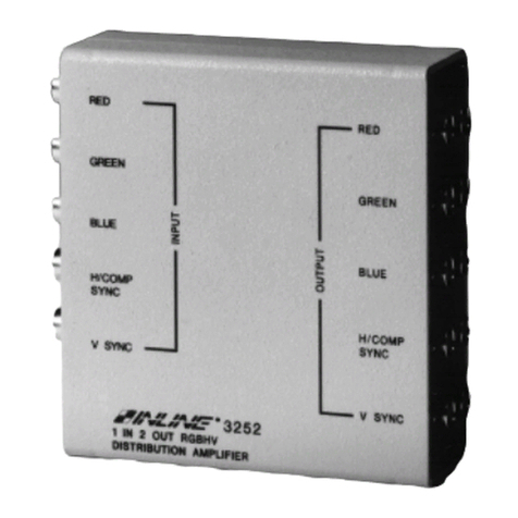
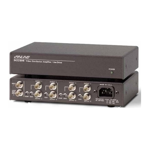
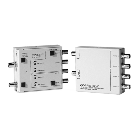
The IN3252HR is a one input, two output distribution amplifier / line driver designed to split a single
RGBHV signal to two data monitors, data projectors, or other RGBHV compatible output devices.
Capable of increasing signal voltage by up to 40%, the IN3252HR also functions as a line driver,
allowing video signals to be sent down longer cables that would be possible without a line driver. Actual
maximum drive distance depends on the resolution of the video signal and is largely determined by the
bandwidth of the cable used for input and output connections.
PRODUCT FEATURES
•Two Buffered Outputs – Allows the signal from one RGBHV source to drive two displays.
•600 MHz Video Bandwidth – Provides superb video performance and compatibility with ultra-high
resolution video signals from graphic workstations.
•External Gain Controls – Individual gain controls for Red, Green and Blue Signals. Permits
accurate adjustment of gray scale and increases signal voltage to drive long cable runs.
•Sharpness Control -- Enhances high resoution video signals. Provides improved image clarity and
boosts visibility of fine details.
•BNC input and output connectors
•Wide Compatibility – Compatible with RGBHV, RGBS, RGsB, RsGsBs, Component, Y/C, High
Resolution Monochrome Video and Composite Video Baseband Signals.
•Loop Output – Provides passive loop-through signal which can drive additional amplifiers to create
a larger DA system or drive a local monitor.
•Metal case enclosure
•Optional Mounting Brackets
COMPATIBILITY
The IN3252HR will operate with RGBHV, RGBS, RGsB, and RsGsBs analog video input signals. When
amplifying RGsB signals (sync on green) and RsGsBs signals (sync on all) only use the red, green, and
blue channels (i.e.: leave the sync channels open.) The red, green, and blue channels may also be used to
amplify or split composite NTSC video signals.
INSTALLATION
1. If operating the IN3252HR without loop output (factory default,) begin with step 2. If operating the
IN3252HR with the loop output connector, please refer to INTERNAL CONTROLS section on
page 3 and set jumpers as appropriate.
2. Connect the red, green, blue, and sync signals from the source to the input of the IN3252HR (see the
Compatibility section for details on Sync on Green and Sync on All signals.)
3. Connect output red, green, blue and sync signals to the display devices or other equipment.
When distributing higher scan rate signals over long cable lengths, cable choice is very critical to
overall system performance. The IN7000-5 / IN7100-5 / IN7200-5 Series High Resolution
RGBHV cables are available in a variety of lengths and are well suited for this purpose.
4. Connect power by plugging in the power supply.
5. Adjust gain and sharpness controls if required (see OPERATION section for details.)

