Inline IN1401 User manual

IN1401 RGB VIDEO SCALER
IN1401
OPERAT ION MANUAL

1
© 2002 - INLINE, Inc. IN1401 Operation Manual - v1.5 7/12/02 11:18 AM
Table of Contents
Product Overview ....................................................................................................... 2
Description............................................................................................................... 2
Compatibility............................................................................................................... 3
Input......................................................................................................................... 3
Output ...................................................................................................................... 3
Installation................................................................................................................... 3
IN1401 Application Diagram .................................................................................. 4
Operation..................................................................................................................... 5
On Screen Menu ...................................................................................................... 5
IN1401 On Screen Display Menu System............................................................... 6
Video Menu ............................................................................................................. 7
Input Menu............................................................................................................... 7
Output Menu............................................................................................................ 8
Options Menu........................................................................................................... 8
Input Settings ......................................................................................................... 10
Very Slow Input Signals........................................................................................ 14
Output Modes......................................................................................................... 14
Default Power Buttons........................................................................................... 14
Output Positioning................................................................................................. 14
Low Power Sleep Mode......................................................................................... 15
Maximum Input and Output Modes....................................................................... 15
Limitations of Settings........................................................................................... 15
Remote Operation..................................................................................................... 16
RS-232 Control...................................................................................................... 16
IN1401 Serial Commands...................................................................................... 17
Specifications............................................................................................................. 19
Troubleshooting........................................................................................................ 20
Warranty ................................................................................................................... 23

2
IN1401 Operation Manual - v1.5 7/12/02 11:18 AM © 2002 - INLINE, Inc.
Product Overview
DESCRIPTION
The IN1401 is an advanced RGB Video Scaler that takes an RGB signal at various scan rates and
resolutions and uses sophisticated digital video scaling technology to convert it to a standard VGA
video signal.
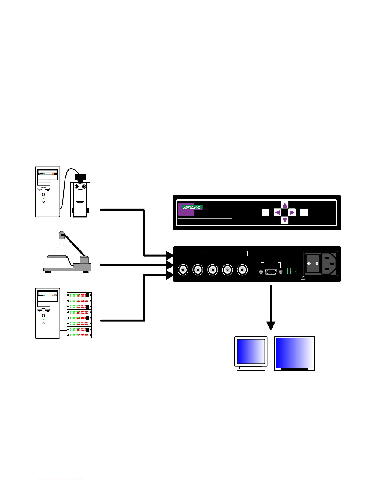
Industrial and Process Control Applications - The IN1401 can act as a bridge between the installed
base of proprietary process control systems and modern data displays. Because the unit accepts a
wide range of standard and non-standard analog video signals and converts them to standard VGA
resolutions and refresh rates, it also allows obsolete, long-persistence phosphor monitors to be
replaced with standard VGA monitors and flat panel displays. The IN1401 also provides enhanced
ergonomics by converting 50 and 60 Hz input signals to higher, flicker-free refresh rates.
A/V Display System Applications - The IN1401 provides an economical way to provide high quality
video scaling of NTSC and PAL RGB video signals from high-resolution cameras, visualizers,
document cameras and other devices featuring an RGB video output. The IN1401 also provides
superb upscaling for 640 x 480, 800 x 600 and 1024 x 768 resolution video signals, making it an
excellent companion for LCD and DLP display devices that have marginal on-board video scaling
capability. The IN1401 has been optimized for scaling RGB computer video signals, RGB signals
from document cameras, and other video signals that do not contain a great deal of fast motion. The
INLINE IN1402, IN1403, IN1404, IN1404XT and IN1408 Video Scalers are recommended for
applications requiring superb video scaling for composite video, S-video, component video and RGB
video signals containing fast, continuous motion.
Comprehensive Input Adjustment Controls - are provided to optimize the unit when used with
propriety and non-standard input signals. These input signal adjustments include: Total Pixels, Active
Pixels, Active Lines, Horizontal and Vertical Blanking, Phase and Scan Type. Once adjustments are
made to optimize non-standard input signals, these settings are stored and automatically recalled when
the same input signal is encountered again.
Blue Screen - This feature provides a full-screen blue image for set-up and testing purposes. The blue
screen output signal (activated via on-screen menu) is always available, even when the input signal is
missing or the input settings are incorrectly adjusted. Blue screen is ideal for establishing the desired
output resolution, refresh rate and position settings, and to verify the connection to the output display
device.
Additional Features Include:
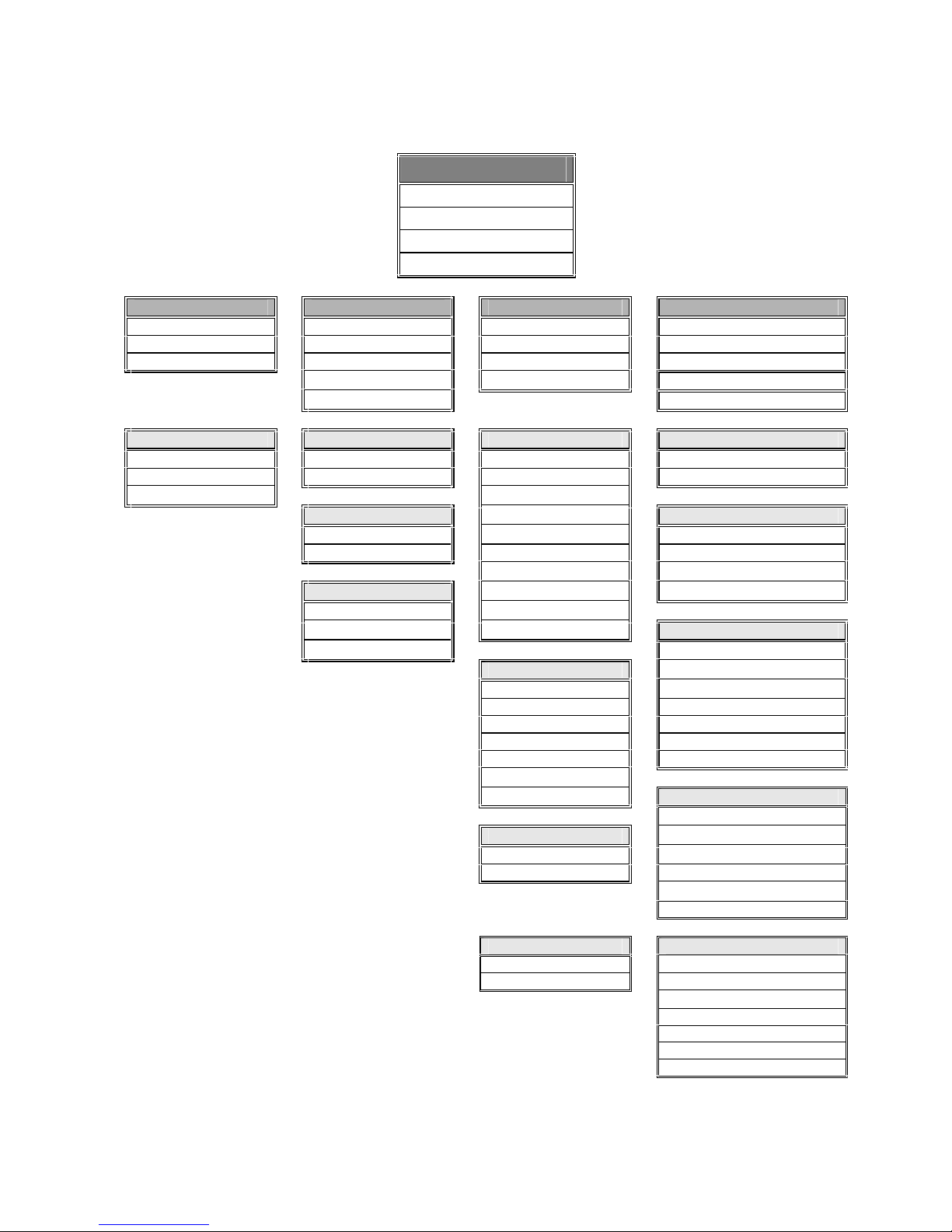
On-Screen Control Menus - provide intuitive control for input and output signal adjustments as well
as advanced settings such as reset to factory defaults. System Info is a menu option that uses the on-
screen display to show comprehensive information about both the input and output signals.
Selectable Output Resolution and Refresh Rate - The IN1401 offers a wide range of output
resolutions to match the optimum or native resolution of virtually any display device.
Output Signal Adjustments - are included for horizontal and vertical positions, brightness and
contrast, and individual gain controls for red, green and blue.

3
© 2002 - INLINE, Inc. IN1401 Operation Manual - v1.5 7/12/02 11:18 AM
RS-232 Serial Control (IN1401-2 Model Only) is provided for all scaler functions including
input selections, image adjustments and output settings. The IN1401-2’s comprehensive RS-232
control capacity facilitates complete system integration and effortless control when combined
with a third party control system.
Data Display Friendly Output - The IN1401 provides a progressive scan RGBHV output at standard
VGA resolutions and refresh rates, ensuring optimal compatibility with a wide range of CRT, LCD,
DMD, ILA, D-ILA, HDLA and Plasma Display devices.
Rack Mountable - Two IN1401 units may be mounted side-by-side using the optional IN9080 Rack
Shelf. A single unit may be rack-mounted using the IN9080 Rack Shelf and an IN9088 Half-Rack
Blank Plate.
Compatibility
INPUT
The IN1401 accepts progressive scan and interlaced RGBHV, RGBS or RGsB analog video signals at
horizontal scan rates from 15 KHz to 60 KHz. The unit automatically adjusts to different sync formats
and a wide variety of input signals including NTSC, PAL and most standard video scan rates.
OUTPUT
The IN1401 output video signal is compatible with a wide range of CRT, LCD, DMD, ILA, D-ILA,
HDLA and Plasma Display devices.
The IN1401 offers a wide range of output resolutions to match the optimum or native resolution of
virtually any display device. The output refresh rate is also selectable as desired. When used with
LCD or DMD displays, the 60 Hz output setting as recommended. Higher output refresh rates may be
selected for use on CRT type displays in order to reduce flicker and provide enhanced ergonomics.
The chart on page 13 indicates the available output resolutions and refresh rates.
Installation
This section offers step-by-step instructions for installing the IN1401 RGB Video Scaler. An
APPLICATION DIAGRAM is located on the following page.
Note: Read the instructions carefully before initiating the installation procedure. Make sure that
there is no power connected to the IN1401, and that the power button is off.
1. Place / install the IN1401 at the desired location. Make sure that the unit is seated on a flat
surface or is securely installed in a standard 19”equipment rack in a 1-U rack space (using the
optional IN9080 rack shelf).
2. Connect the IN1401 input (BNC connectors) to a data output device (featuring an RGB video
output), using three, four or five BNC cables (for RGsB, RGBS or RGBHV, respectively) or a
multi-conductor RGBHV, RGBS or RGB "snake". The IN7000 / IN7200 / IN7300 Series cables
are well suited for this purpose (see RGB Output Cables on page 15). While making connections,
take care to insure that the red output is connected to the red input, green output to the green
input, etc.
Note: The IN1401 will not accept S-Video or composite video signals.

4
IN1401 Operation Manual - v1.5 7/12/02 11:18 AM © 2002 - INLINE, Inc.
3. Connect the monitor, flat panel or other VGA display device directly to the IN1401 output port
using a standard 15-pin HD male-to-male VGA cable. INLINE’s IN8000M Series VGA cables
offer exceptional performance and are available in a variety of lengths.
4. Connect power to the IN1401 using the IN9230 IEC power cable (included).
5. Turn on the video source, the IN1401 and the monitor. The scaler has been factory pre-set to
support plug and play operation with most display devices. If it becomes necessary to manually
adjust / fine-tune the video image, refer to the INPUT SETTINGS section on pages 8 - 11 to
achieve optimum picture quality.
IN1401 APPLICATION DIAGRAM
!
H/C
VBG/GsR
FUSE; 0.5 A; 250 V; TIME DELAY
90-260 VAC; 0.20 A; 47-63 HZ
TECHNICAL SUPPORT: (800)882-7117
(714)921-4100
www.inlineinc.com
INPUT
IN1401 RGB Video Scaler
Monitor
IN1401 REAR VIEW
Video Microscope with RGB output
MENU ENTER
OUTPUT
TX GND RX
RS-232
IN1401 FRONT VIEW
Flat Panel Display
Process Controller
Document Camera with RGB output

5
© 2002 - INLINE, Inc. IN1401 Operation Manual - v1.5 7/12/02 11:18 AM
Operation
ON SCREEN MENU
This section offers a description of the on screen menus and their operations. To access the Main
Menu, press the MENU or ENTER Button. Use the arrow buttons to maneuver around within
the menu display(s). Press ENTER to select a command, and press MENU to exit.
The MAIN MENU commands and their functions are:
VIDEO - Changes input signal video parameters
INPUT - Changes input signal-timing parameters
OUTPUT - Changes output signal-timing parameters
OPTIONS - Displays advanced options
An illustration of the On Screen Display Menu System is provided on page 6, followed by a
detailed description of each menu command.

6
IN1401 Operation Manual - v1.5 7/12/02 11:18 AM © 2002 - INLINE, Inc.
IN1401 ON SCREEN DISPLAY MENU SYSTEM
Main Menu
Video
Input
Output
Options
Video Input Output Options
Brightness Blanking Resolution Factory Reset
Contrast Active Area Refresh Rate Auto Detect
Color Total Pixels Position Baud Rate
Phase Blue Screen Delimiters
Scan Type System Info.
Color Blanking Resolution Factory Reset
Red H-Blanking 640 x 480 Yes
Green V-Blanking 800 x 600 No
Blue 852 x 480
Active Area 1024 x 768 Auto Detect
Active Pixels 1152 x 864 Auto Detect On
Active Lines 1280 x 720 Auto Detect Off
1280 x 768 User Defined
Sync Type 1280 x 1024 Redetected Now
Interlaced 1365 x 768
Swap Fields 1365 x 1024 Baud Rate**
Invert Sync
1200
Refresh Rate* 2400
56 / 60 / 65 Hz 4800
72 Hz 9600
75 Hz 1920
85 Hz 38400
96 Hz 57600
100 Hz
120 Hz
Delimiters**
Brackets [ ]
Position Braces { }
H-Position Parentheses ( )
V-Position Slashes / \
Greater / Less than < >
Signs ! #
Blue Screen System Info
On Input
Off Horizontal
Vertical
Output
Horizontal
Vertical
Version
* Depends on the resolution **Functional for IN1401-2 Only

7
© 2002 - INLINE, Inc. IN1401 Operation Manual - v1.5 7/12/02 11:18 AM
VIDEO MENU
BRIGHTNESS - Changes the input signal brightness
CONTRAST - Changes the input signal contrast
COLOR - Changes the input signal gain (contrast) for each individual color. Red, green and
blue are available.
INPUT MENU
H-BLANKING - The number of pixels per line inside the blanking area that is on the left side
of the active area (including the horizontal sync width and the horizontal back porch).
V-BLANKING - The number of lines per frame inside the blanking area that is above the active
area (including the vertical sync height and the vertical back porch).
ACTIVE PIXELS - The number of pixels per line inside the active input area.
ACTIVE LINES - The number of lines per frame inside the input active area. For interlaced
input signals, this number refers to the lines per frame after de-interlacing, not the
number of lines per field.
TOTAL PIXELS - The total number of pixels per line including the blanking on both sides of
the input active area (active, horizontal sync width, back porch and front porch). Refer to
the Input Settings section on pages 8-11 to determine how to set the total pixels. The
total number of lines per frame including the blanking above and below the active area is
determined by the input signal and cannot be adjusted by the user.
PHASE - Adjusts the amount of phase shift applied to the input signal.
SCAN TYPE - Three options are available:
• Interlaced - for interlaced signals
• Swap fields - to switch the interlaced fields (if necessary)
• Invert Sync - to switch the sync polarity (if necessary)

8
IN1401 Operation Manual - v1.5 7/12/02 11:18 AM © 2002 - INLINE, Inc.
OUTPUT MENU
RESOLUTION - Because the IN1401 only scales up, users must choose an output resolution
that is greater than or equal to the input active area, as well as one that is compatible with
their monitor. The available resolution rates are listed on page 13.
REFRESH RATE - Allows users to choose the refresh rate that’s compatible with their display
device.
Note: Not all resolution and refresh rate combinations are available. Refer to the chart
on page 13 for a complete listing.
POSITION - Positions the output image on the monitor. Unlike input blanking it does not crop
the image or add blank borders.
BLUE SCREEN - Adjusts the output image on the monitor. Available anytime (even when the
input settings are incorrectly adjusted or the input signal is missed entirely), the blue
screen is used to adjust the outer settings (resolution, refresh rate and position) and verify
the image on the monitor. The video and input settings have no effect on the blue screen.
Once the output settings have been properly adjusted and verified on the monitor, the
blue screen may be turned off to adjust the video and input settings.
OPTIONS MENU
FACTORY RESET - Returns all video, input and output settings to factory default (except the
resolution and refresh rate).
AUTO DETECT - Four options are available:
• Auto Detect On - The default mode at power up that allows the IN1401 to
automatically detect new input modes and adjust accordingly.
• Auto Detect Off - Prevents the IN1401 from switching back and forth between
input modes, or flickering when small input changes occur (such as from a VCR in
fast forward or reverse).
• User Defined - All input modes have the same user definable settings, however,
they are restricted to values close to the input mode detected. If a full range of values
is necessary, the user-defined mode may be manually selected.
Note: If auto detect cannot determine the input mode, the user defined mode is
selected automatically.
• Redetected Now - The IN1401 automatically reconfigures when each new input
mode is detected and each new output mode is selected. In the event that the scaler
does not detect a change in the input mode, or should the input / output settings
become invalid, the Redetect Now option allows users to initiate a new detection
sequence and reload the input / output settings.
BAUD RATE - Allows RS-232 remote users to select the baud rate that matches their remote
control device system.
DELIMITERS - Use the on screen menu to select the desired command code delimiters.
INLINE scalers can be set to recognize six sets of leading and end codes when using an
RS-232 remote: parentheses ( ), brackets [ ], braces{ }, slashes \ /, less and greater than <
>, and signs !#. If desired, several INLINE products may be connected together on the

9
© 2002 - INLINE, Inc. IN1401 Operation Manual - v1.5 7/12/02 11:18 AM
same RS-232 serial control line with each device set for a different delimiter pair. Each
unit will only respond to codes sent with the appropriate delimiters and will ignore all
other codes.
SYSTEM INFO - This screen displays the following system information:
• Input Active Area • Input Horizontal Scan Rate
• Input Vertical Refresh Rate • If Input is Interlaced
• Output Resolution • Output Horizontal Scan Rate
• Output Vertical Refresh Rate • Program Version Number
Only the input horizontal scan rate and input vertical refresh rate are measured by the IN1401. If
the input signal includes extra pulses (such as equalization or serration pulses), the input vertical
refresh rate may indicate a value lower that the actual rate. All other values are simply repeated
as defined by the input and output settings. Although the IN1401 detects the input mode and
adjusts automatically (for the detected input mode and the selected output mode), the system will
reflect any changes made to these settings made by the user. This information may be useful for
setting other video parameters such as the input total pixels (see input settings below) or for other
video equipment connected to the IN1401.

10
IN1401 Operation Manual - v1.5 7/12/02 11:18 AM © 2002 - INLINE, Inc.
INPUT SETTINGS
The IN1401 adjusts automatically for different input and output modes. However, in cases where
the input signal has slightly different timing or is a non-standard mode, some settings may be
adjusted manually. All settings for each input and output mode (including non-standard input
modes) are stored internally so the adjustments will not have to be repeated after they are
optimized. The input settings are shown in Figure 1 and the formulas and figures listed on the
following pages will assist in the adjustment of these settings.
Blanking Area
Active Area
H-Blanking Active Pixels
Active Lines
V-Blanking
Total Pixels
Total Lines
Figure 1. Input Settings
The input settings control the following:
• H-Blanking - Left edge of image • V-Blanking - Top edge of image
• Active Pixels - Right edge of image • Active Lines - Bottom edge of image
• Total Pixels - Right edge of image
Use these controls to match the input video signal, framing the actual active area.
Note: Active pixels and total pixels are interactive. Setting one may require re-adjusting the other.

11
© 2002 - INLINE, Inc. IN1401 Operation Manual - v1.5 7/12/02 11:18 AM
In Figure 2, the input blanking is set incorrectly (as indicated by the dashed lines). If the H-
Blanking is set less than the actual H-Blanking, the IN1401 will look for the active area before it
really occurs. This results in a blank border on the left side of the active area, and cropping on
the right side of the active area. This gives the apparent effect that the image is shifted to the
right. Similarly, if the V-Blanking is set less than the actual V-Blanking, the IN1401 will again
look for the active area before it really occurs. This results in a blank border on top of the active
area, and cropping on the bottom of the active area. This gives the apparent effect that the image
is shifted down.
Incorrect Blanking
H-Blanking
V-Blanking
Active Area
Active Blanking Area
Figure 2. Incorrect Input Blanking
Do not confuse input blanking with the output position. The input blanking adjusts where the
electronic scaling process takes effect, which may add blank borders or crop the active area if set
incorrectly. The input blanking and active area should be manually adjusted to match the input
video signal, framing the actual active area on the monitor.
The output position simply moves the image on the monitor. It does not add blank borders or
crop any part of the image. However, the apparent effect of blank borders and a cropped image
may be due to the image being incorrectly positioned on the monitor. The blue screen is available
to adjust the output image on the monitor. It as available at any time, even when the input
settings are incorrectly adjusted or the input signal is missing entirely. Use the blue screen to
adjust the output settings (resolution, refresh rate and position) and to verify the image on the
monitor. The video and input settings have no effect on the blue screen. Once the output settings
have been properly adjusted and verified on the monitor, the blue screen can be turned off, and
the video settings may then be adjusted.

12
IN1401 Operation Manual - v1.5 7/12/02 11:18 AM © 2002 - INLINE, Inc.
In Figure 3, the active area is adjusted incorrectly, as shown by the dashed lines. If the active pixels are set less
that the actual active pixels, the IN1401 will only look for the active area inside this smaller region. This results
in an active area containing fewer pixels than are really present. This gives the apparent effect that the picture is
stretched horizontally. Similarly, if the active lines are set less than the actual active lines, the IN1401 will again
only look for the active area inside the smaller region. This results in an active area containing fewer lines than
are really present. This gives the apparent effect that the image is stretched vertically.
Blanking
Active Area
Active Pixels
Active Lines
Incorrect Active
Figure 3. Incorrect Active Area
Depending on the video source, the following input modes may have the same horizontal scan rate and
vertical refresh rate. The differences between these input modes will not be detected. The input aspect
ratio will automatically be maintained at the output by inserting blank borders around the image. However,
if you want to fill the entire monitor, the input aspect ratio may be set by adjusting the active pixels or
active lines, according to the input mode. This will stretch the image to fill the entire monitor. The total
pixels may also be adjusted to match the input mode as shown in the tables below:
Table 1. Input Modes for Horizontal Scan Rate = 31.5 KHz and Vertical Refresh Rate = 60 Hz
Active Pixels Active Lines Aspect Ratio Total Pixels
640 480 4:3 780 (progressive NTSC)
640 350 64:35 800
640 400 8:5 800
640 480 4:3 800 (factory default)
720 350 72:35 900
720 400 9:5 900
Table 2. Input Modes for Horizontal Scan Rate = 15.7 KHz and Vertical Refresh Rate = 60 Hz
Active Pixels Active Lines Aspect Ratio Total Pixels
768 480 8:5 910 NTSC 14.3
720 480 3:2 858 NTSC 13.5
640 480 4:3 780 NTSC 12.3 (default)

13
© 2002 - INLINE, Inc. IN1401 Operation Manual - v1.5 7/12/02 11:18 AM
In Figure 4, the total pixels are adjusted incorrectly. There are several ways to set the total
pixels. It is best to set the total pixels according to the input signal specifications. Otherwise, if
the input pixel clock is known, the input total pixels may be calculated using one of the methods
shown below:
• Check the On-Screen Menu: The input horizontal scan rate, as measured by the
IN1401, may be found in the options menu under SYSTEMS INFO on page 7.
• Multiply the input active pixels by 1.3 to approximate the input total pixels.
• Adjust the input total pixels to minimize any faint vertical lines that may be seen
within the image, as shown below in Figure 4.
The total pixels may be adjusted to move the lines closer together or further apart. Adjust the
total pixels until the lines are furthest apart or until they are completely out of view. If one line
still remains, it may be moved out of view using the phase adjustment. The input active pixels
and total pixels are interactive. Setting one may require readjustment of the other.
1. Set input total pixels according to input signal specifications.
2. Input total pixels = input pixel clock / input horizontal scan rate.
3. Input total pixels ≈1.3 x input active pixels.
4. Set input total pixels to minimize faint vertical lines (see Figure 4).
5. After the input active pixels have been set correctly, adjust total pixels for the
correct active width.
Blanking Area
Active
Area
Total Pixels
Figure 4. Incorrect Total Pixels

14
IN1401 Operation Manual - v1.5 7/12/02 11:18 AM © 2002 - INLINE, Inc.
VERY SLOW INPUT SIGNALS
If the input signal is very slow (pixel clock is less than 12 MHz), the IN1401 may display a poor
image as it is only designed for signals above 12 MHz. To improve the quality of the image,
simply increase the sampling rate by doubling the number of active pixels and total pixels by
using the on screen menu. The number of active lines remains the same. For example:
Parameter Actual Input Signal IN1401 Settings
Active Pixels 380 760
Active Lines 286 286
Total Pixels 482 964
Pixel Clock 7.512 MHz 15.024 MHz
OUTPUT MODES
The IN1401 supports the following Output Modes:
Refresh Rate (Hz)
Resolution Mode Aspect Ratio* 56 60 65 72 75 85 96 100 120
640 x 480 VGA 4:3
800 x 600 SVGA 4:3
852 x 480 HDTV - 480p 16:9
1024 x 768 XGA 4:3
1152 x 864 4:3
1280 x 720 HDTV –720p 16:9
1280 x 768 16:9
1280 x 1024 SXGA 5:4
1365 x 768 Wide XGA 16:9
1365 x 1024 4:3
DEFAULT POWER-UP BUTTONS
An output mode or a factory reset may be selected without the use of the IN1401 menu. This is
particularly useful if the monitor does not display an image or if the image is scrambled. Simply
hold down the front panel button while turning on the IN1401. To select both an output mode
and factory reset, hold down both buttons simultaneously while turning the scaler on.
MENU: 640 x 480 @ 60 Hz DOWN: 1152 x 864 @ 60 Hz
LEFT: 800 x 600 @ 60 Hz RIGHT: 1280 x 1024 @ 60 Hz
UP: 1024 x 768 @ 60 Hz ENTER: Factory Reset
OUTPUT POSITIONING
The output may be adjusted without entering the main menu sequence. Pressing the arrow keys
selects the output position controls if the menu is not on. Afterwards, press enter to save the
output position, or press menu to exit without saving the output position.

15
© 2002 - INLINE, Inc. IN1401 Operation Manual - v1.5 7/12/02 11:18 AM
LOW POWER SLEEP MODE
If no input signal is detected, the IN1401 will enter a low power sleep mode operation.
During this mode, the processor is still active and will continue to monitor the input for any
video signal. Upon connection to the video signal, the IN1401 will automatically return to its
normal mode of operation. The IN1401 menu may be displayed and adjusted without any
video signal connected. If the IN1401 is in its low power mode, press menu or enter to turn
on the unit and start the menu. All controls are available. The background will be blue if no
signal is present and cannot be turned off until a signal is connected. Upon exiting the menu,
the IN1401 will again return to its low power mode if no signal is present.
MAXIMUM INPUT AND OUTPUT MODES
There are six factors that limit the input and output modes of the IN1401:
1. Input Active Pixels ≤Output Active Pixels
2. Input Active Lines ≤Output Active Lines
3. Input Pixel Clock ≤95 MHz (After De-Interlacing)
4. Intermediate Pixel Clock ≤95 MHz (After Frame Rate Conversion)
5. Output Pixel Clock ≤135 MHz (After Image Scaling)
6. (Input Pixel Clock + 95) / 1.8 ≤95 (Bandwidth Formula)
LIMITATIONS OF SETTINGS
The following criteria must be met for all signals. Any attempt to adjust the settings beyond
these criteria results in an invalid video signal and will not be allowed. If any setting will not
move to the desired value, verify the equations below and refer to the list of problems /
solutions on page 17 of the Troubleshooting Section to find the alternate setting required.
Input Total Pixels > Input H-Blanking + Input Active Pixels
Input Active Pixels < Input Total Pixels - Input H-Blanking
Input Active Pixels ≤Output Active Pixels
Input Active Lines < Input Total Lines - Input V-Blanking
Input Active Lines ≤Output Active Lines
Input H-Blanking < Input Total Pixels - Input Active Pixels
Input V-Blanking < Input Total Lines - Input Active Lines
In addition to the above limitations, the predefined input modes only have a full range of 256
units. If a setting beyond +/- 128 units from the default value is desired, the user-defined
mode may be selected.
Note: All of the limits listed above apply to the user-defined mode.

16
IN1401 Operation Manual - v1.5 7/12/02 11:18 AM © 2002 - INLINE, Inc.
Remote Operation (IN1401-2 Only)
RS-232 CONTROL
The IN1401-2 model has an RS-232 serial control port that accepts serial commands from a control
system, computer serial port, or any other device capable of sending out serial ASCII commands at
compatible baud rates. A complete listing of RS-232 codes is included on the following pages.
Communication Protocol:
8 data bits
1 stop bit
No parity check
9600 baud (factory default setting)
Baud Rate Selection:
The IN1401 has a factory default baud rate of 9600 bps and can communicate at baud rates from 1200
up to 57,600. Baud rates can be selected using the Advanced Menu (see page 23).
ÁNote: The baud rate transmitted must match the baud rate selected on the IN1401
Command Code Structure and Delimiters:
All commands sent to the unit must contain a leading code, the command code, and an ending code.
Each command must be completely executed before the unit will accept a new command.
INLINE scalers can be set to recognize six sets of leading and end codes (delimiters) when using an
RS-232 remote: parentheses ( ), brackets [ ], braces{ }, slashes \ /, less and greater than < >, and
signs !#. The factory default serial delimiters are [ ].
Note: Only the IN1401 that has the same delimiters as the remote controller will respond.
A complete command consists of:
[The leading code
CH3 The command code.
]The ending code
Example: [CH3] commands the IN1401 to select channel 3.
Serial Control Cable Wiring
When controlling only one IN1401 unit, connect the RS-232 cable as follows:
Controller Transmit to IN1401 Receive
Controller Ground to IN1401 Ground
Controller Receive to IN1401 Transmit
When controlling multiple IN1401 units, connect the RS-232 cable as follows:
Controller Transmit to Each IN1401 Receive
Controller Ground to Each IN1401 Ground
Controller Receive to Only one IN1401 Transmit

17
© 2002 - INLINE, Inc. IN1401 Operation Manual - v1.5 7/12/02 11:18 AM
Key Concept
IN1401 SERIAL COMMANDS
COMMAND DESCRIPTION
ACI3 set baud rate to 1200
ACI4 set baud rate to 2400
ACI5 set baud rate to 4800
ACI6 set baud rate to 9600**
ACI7 set baud rate to 19,200
ACI8 set baud rate to 38,400
ACI9 set baud rate to 57,600
ACI? return baud rate
AL+ increase active lines
AL- decrease active lines
AL@ set active lines to
normal**♦
ALxxx set active lines to absolute
value♦
AL? return active lines
AP+ increase active pixels by 2
AP- decrease active pixels by 2
AP@ set active pixels to
normal**♦
APxxx set active pixels to absolute
value♦
AP? return active pixels
BH+ increase input horizontal
blanking
BH- decrease input horizontal
blanking
BH@ set input horizontal
blanking to normal**♦
BHxxx set input horizontal
blanking to absolute
value♦
BH? return input horizontal
blanking
BLU+ increase blue gain
BLU- decrease blue gain
BLU@ set blue gain to
normal**(128)
COMMAND DESCRIPTION
BLUxxx set blue gain to absolute
value (0-255)
BLU? Return blue gain
BLS0 blue screen ON
BLS1 blue screen OFF
BV+ increase input vertical
blanking
BV- decrease input vertical
blanking
BV@ set input vertical blanking
to normal**♦
BVxxx set input vertical blanking
to absolute value♦
BV? return input vertical
blanking
BRG+ increase brightness
BRG- decrease brightness
BRG@ set brightness to normal**
(128)
BRGxxx set brightness to absolute
value (000-255)
BRG? return current brightness
CMDCD0 set delimiters to brackets [
]**
CMDCD1 set delimiters to braces { }
CMDCD2 set delimiters to
parentheses ( )
CMDCD3 set delimiters to less and
greater < >
CMDCD4 set delimiters to slashes \ /
CMDCD5 set delimiters to signs !#
CMDCD? Return delimiters
CON+ increase contrast
CON- decrease contrast
CON@ set contrast to normal**
(128)
CONxxx set contrast to absolute
value (000-255)
When controlling multiple units, the Controller Receiver Terminal must con-
nect to only one IN1401 Transmit Terminal. Multiple IN1401 Transit Lines
may not be connected together; otherwise signal contention from multiple
units will result. Therefore, “receive” information is only available from one
IN1401 in this configuration. Each unit must be set to different delimiters.

18
IN1401 Operation Manual - v1.5 7/12/02 11:18 AM © 2002 - INLINE, Inc.
COMMAND DESCRIPTION
CON? return current contrast
DOWN front panel down button.
ENTER front panel enter key.
GRN+ increase green gain
GRN- decrease green gain
GRN@ set green gain to
normal**(128)
GRNxxx set green gain to absolute
value(0-255)
GRN? return green gain
IM0 set input mode to auto
detect ON**
IM1 set input mode to auto
detect OFF
IM2 set input mode to user
defined
IM3 redetect input mode now
IM? return input mode state
INFO? return unit version
LEFT front panel left key.
MENU front panel menu key.
PH+ increase horizontal position
PH- decrease horizontal
position
PH@ set horizontal position to
normal**♦
PHxxx set horizontal position to
absolute value♦
PH? return current horizontal
position
PHS+ increase phase
PHS- decrease phase
PHS@ set phase to normal**♦
PHSxxx set phase to absolute value
PHS? return phase
PV+ increase vertical position
PV- decrease vertical position
PV@ set vertical position to
normal** ♦
PVxxx set vertical position to
absolute valuε♦
COMMAND DESCRIPTION
PV? return current horizontal
position
RED+ increase red gain
RED- decrease red gain
RED@ set red gain to
normal**(128)
REDxxx set red gain to absolute
value (0-255)
RED? return red gain
REF0 set refresh rate to 60Hz**
REF1 set refresh rate to 72Hz
REF2 set refresh rate to 75Hz
REF3 set refresh rate to 85Hz
REF4 set refresh rate to 96Hz
REF5 set refresh rate to 100 Hz
REF6 set refresh rate to 120Hz
REF? return refresh rate
RES000 factory reset
RIGHT front panel right key.
SCS0 set resolution to 640 x 480
SCS1 set resolution to 800 x 600
SCS2 set resolution to 852 x 480
SCS3 set resolution to 1024 x 768
SCS4 set resolution to 1152 x 864
SCS5 set resolution to 1280 x 720
SCS6 set resolution to 1280 x 768
SCS7 set resolution to 1280 x
1024
SCS8 set resolution to 1365 x 768
SCS9 set resolution to 1365 x
1024
SCS? return current resolution
ST0 toggle interlaced(1=on)
ST1 toggle swapped
fields(10=on)
ST2 toggle invert sync(100=on)
ST? return scan type (add above
numbers)
UP front panel up key.
* This Command List is preliminary. The commands are not case sensitive.
** Default values when factory reset is performed.
♦Normal and available values depend on the current input or output mode

19
© 2002 - INLINE, Inc. IN1401 Operation Manual - v1.5 7/12/02 11:18 AM
Specifications
IN1401 RGB Video Scaler
Input
Connectors (5) Female BNC for RGBHV, RGBS, RGsB
Signal 0.7 Vp-p typical, 75 Ohm impedance
Signal Type Analog Video, Progressive Scan or Interlaced
Horizontal Scan Rate 15 KHz - 60 KHz
Refresh Rates 50 Hz - 120 Hz
Output
Connectors (1) 15-Pin HD Female for RGBHV
RGB Video 0.7 Vp-p typical, 75 Ohm Impedance
Sync H & V: TTL compatible
Resolution 640 x 480 to 1365 x 1024 (see chart on page 11)
Refresh Rate 60 Hz to 120 Hz (see chart on page 11)
Color Depth 24-bit
General
RS-232 Control
(IN1401-2 Only) 1200 to 57,600 baud, N, 8, 1; 3-Pin Phoenix
Power Supply Internal Switch Mode: 90 - 260 VAC; 47 - 63 Hz
Power Consumption 15 Watts
Shipping Weight 4 lbs. / 2 Kg
Product Weight 2 lbs. / 0.9 Kg
Dimensions 1.65”x 8.5”x 7.3”/ 4.2 cm x 21.6 cm x 18.5 cm
Regulatory Approvals UL1950, CAN/CSA-22.2 No. 950, 3rd Edition
CE: EN55022 (1987), EN50081-1 (1991),
EN50082-1 (1992 and 1994), EN60950-92
Included Accessories
IN9230 IEC Power Cable, 6’long (USA only)
Operations Manual
Optional Accessories
VGA Monitor Adapter and Extension Cables
IN8000M Series -15-pin HD male to 15-pin HD male, available in various lengths
Installation Cables
IN7000P-5 Series RGBHV Cable: Standard Resolution, Plenum Cable
available in bulk lengths
IN7000P-5K Series RGBHV Cable: Standard Resolution, Plenum Cable
available in 1000’bulk length
Rack-Mount Hardware
IN9080 - Rack Shelf
IN9088 - Half-Rack Blank Plate
Table of contents
Other Inline Media Converter manuals