Inmarsat Wideye Sabre Ranger Series User manual

1
SABRETM Ranger Installation Guide
© Copyright 2009 Addvalue Communications Pte Ltd.
All rights reserved. This publication and its contents are proprietary to Addvalue
Communications Pte Ltd. No part of this publication may be reproduced
in any form or by any means without the written permission of Addvalue
Communications Pte Ltd., 190, Changi Road, #02-02, MDIS Building, Singapore
419974.
Addvalue Communications Pte Ltd has made every effort to ensure the
correctness and completeness of the material in this document. Addvalue
Communications Pte Ltd shall not be liable for errors contained herein. The
information in this document is subject to change without notice. Addvalue
Communications Pte Ltd makes no warranty of any kind with regard to this
material,including,butnotlimitedto,theimpliedwarrantiesofmerchantability
and fitness for a particular purpose.
All trademarks, marks, names, or product names referenced in this publication
are the property of their respective owners, and Addvalue Communications
Pte Ltd neither endorses nor otherwise sponsors any such products or services
referred to herein.
SABRE™ and IOTA™ are trademarks of Addvalue Communications Pte Ltd.
Microsoft,Windows,WindowsNT,Windows2000,andWindowsXPareregistered
trademarks of Microsoft Corporation in the U.S.A. and/or other countries.
INMARSAT is a trademark of the International Mobile Satellite Organization.
The Inmarsat LOGO and the trademark BGAN are trademarks of Inmarsat (IP)
Company Limited. All trademarks are licensed to Inmarsat Limited.
All other company and product names may be the registered trademarks or
trademarks of their respective owners.
SABRE™ Ranger Installation Guide [May 2009]
Copyright
Warranty
Trademarks
SABRETM Ranger Installation Guide
2
Congratulations on the purchase of your SABRETM Ranger terminal.
When you unpack the package, please check that the following items are
present:
• SABRETM Ranger terminal
• AC/DC power adapter with power cable
• Mounting Frame (including four allen screws with washers, four bolts
with nuts and washers)
• Two U-bolts with four washers and nuts
• Ethernet cable (RJ45, Cat 5 Straight, 1.5m)
• Phone cable (RJ11, 1.8m)
• Multi-function cable (10 metres, packed separately)
• Heater power cable (only for SABRETM Ranger-V2)*
• AC/DC power adapter with power cable (additional unit only for
SABRETM Ranger-V2)*
• Installation guide
• Product CD (software utilities and documentations)
If any of the items are missing from the package, please contact your reseller
where you have purchased the SABRETM Ranger terminal package.
Note:
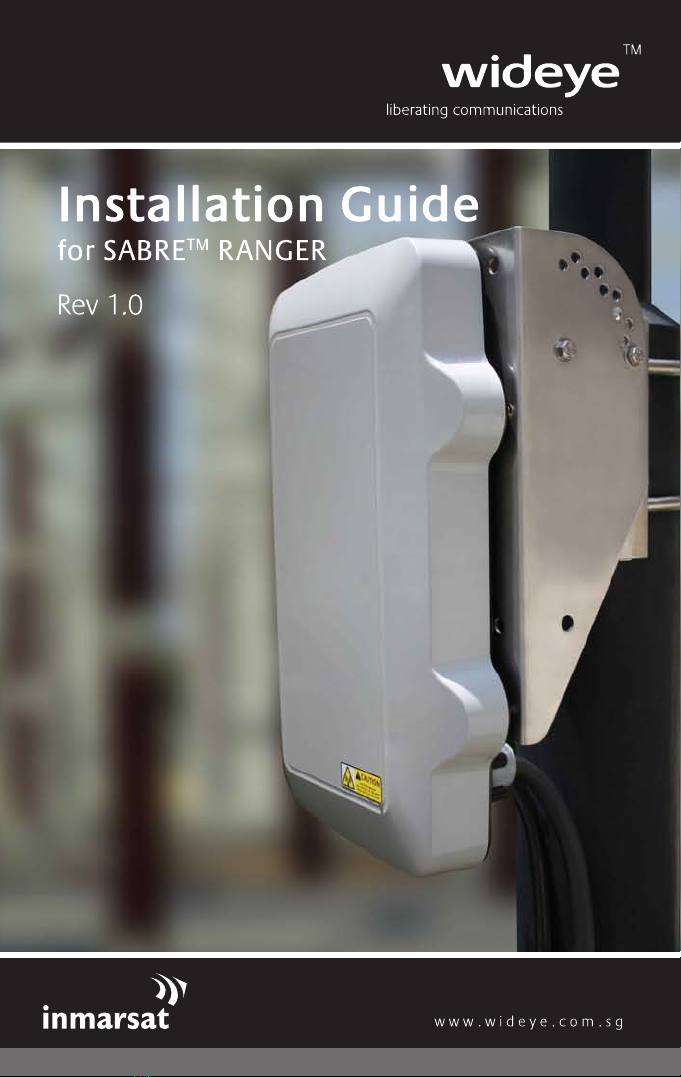
There are two variants of the SABRETM Ranger terminal:
Note*:
The pictures used in this guide shows the SABRETM Ranger-V2 terminal with the
heater option.
SABRETM Ranger-V1:
Terminal without the heater option
has only one cable gland hole on
the connector cover to connect the
Multi-function cable.
SABRETM Ranger-V2*:
Terminal with the heater option
has two cable glands holes on the
connector cover to connect the
Multi-function and Heater power
cables.
1 Getting Started
3
SABRETM Ranger Installation Guide
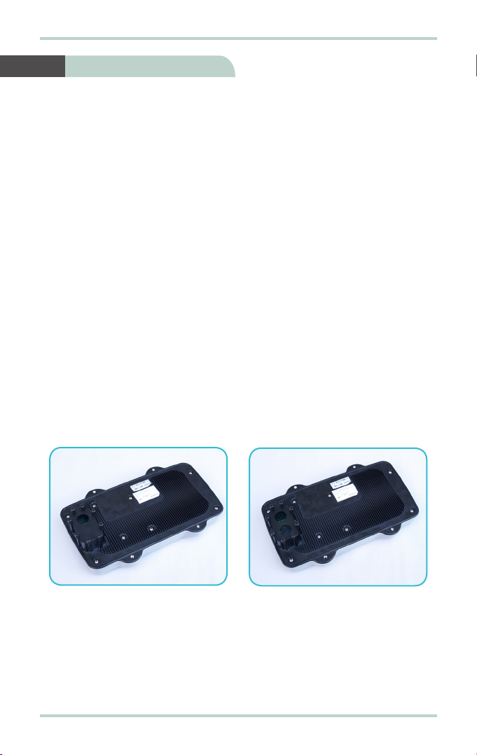
Follow these steps to install the SIM card:
1. Remove the eight thumb-head screws securing the connector cover.
2. Remove and keep the connector cover and the eight thumb-head screws in
a safe location.
3. Push tab and lift up the SIM card slot.
SIM card slot
Tab
2 Installing SIM Card
Connector
Cover

SABRETM Ranger Installation Guide
4
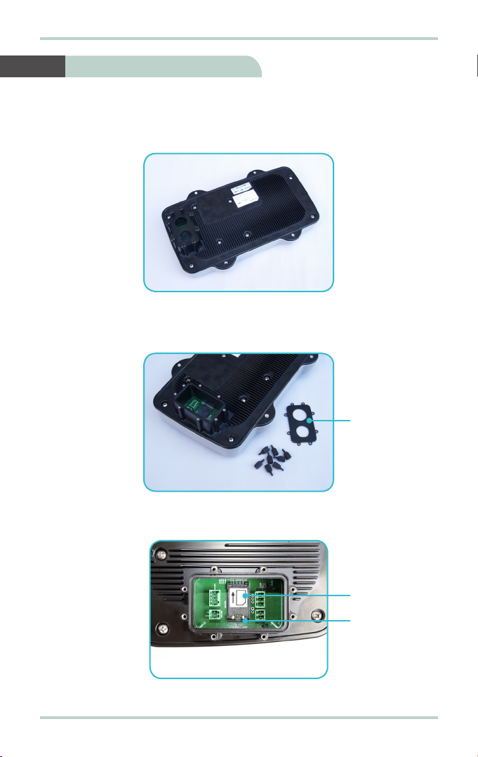
Follow these steps to connect the Multi-function and Heater power cables:
1. Remove the running couplers from the cable glands attached to the Multi-
function and Heater power cables.
4. With the gold-contacts facing down, position the SIM card as indicated and
slide the SIM card into the slot.
5. Push the SIM card slot down until it clicks and lock in place.
Heater
power
cable
Multi-function
cable
3 Connecting the Multi-function
and Heater Power Cables
5
SABRETM Ranger Installation Guide
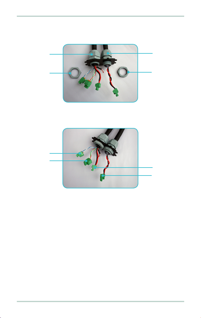
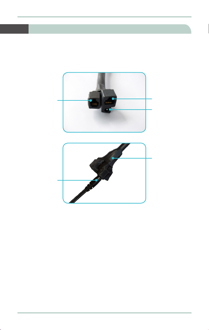
2. Thread the three connectors of the Multi-function cable and the connector
of the Heater power cable through the connector cover.
3. Install running couplers to secure the Multi-function and Heater power
cables to the connector cover.
Running
coupler
Cable
gland
Cable
gland
Running
coupler
Heater
power
plug
Power
plug
Ethernet
plug
Phone
plug

SABRETM Ranger Installation Guide
6
4. Install the Multi-function and Heater power cable plugs to the respective
headers on the SABRETM Ranger terminal.
5. Install and secure the connector cover with the eight thumb-head screws.
Power
header
Heater
power
header
Ethernet
header
Phone
header

7
SABRETM Ranger Installation Guide
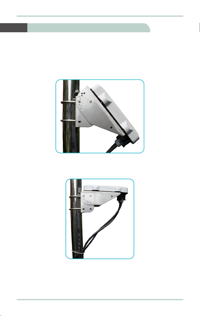
Follow these steps to setup the mounting frame:
1. Align the mounting frame.
2. Install four bolts with washers to secure the mounting frame together.
Follow these steps to install the mounting frame:
1. Place mounting frame on the back end of the SABRETM Ranger terminal.
Note:
The mounting frame can be installed in the vertical or horizontal position
as shown below.
2. Orientate the mounting frame to desired position.
3. Install four allen-screws with washers to secure mounting frame to the
SABRETM Ranger terminal.
4 Setting Up the Mounting Frame
5 Installing the Mounting Frame
Horizontal positionVertical position
SABRETM Ranger Installation Guide
8
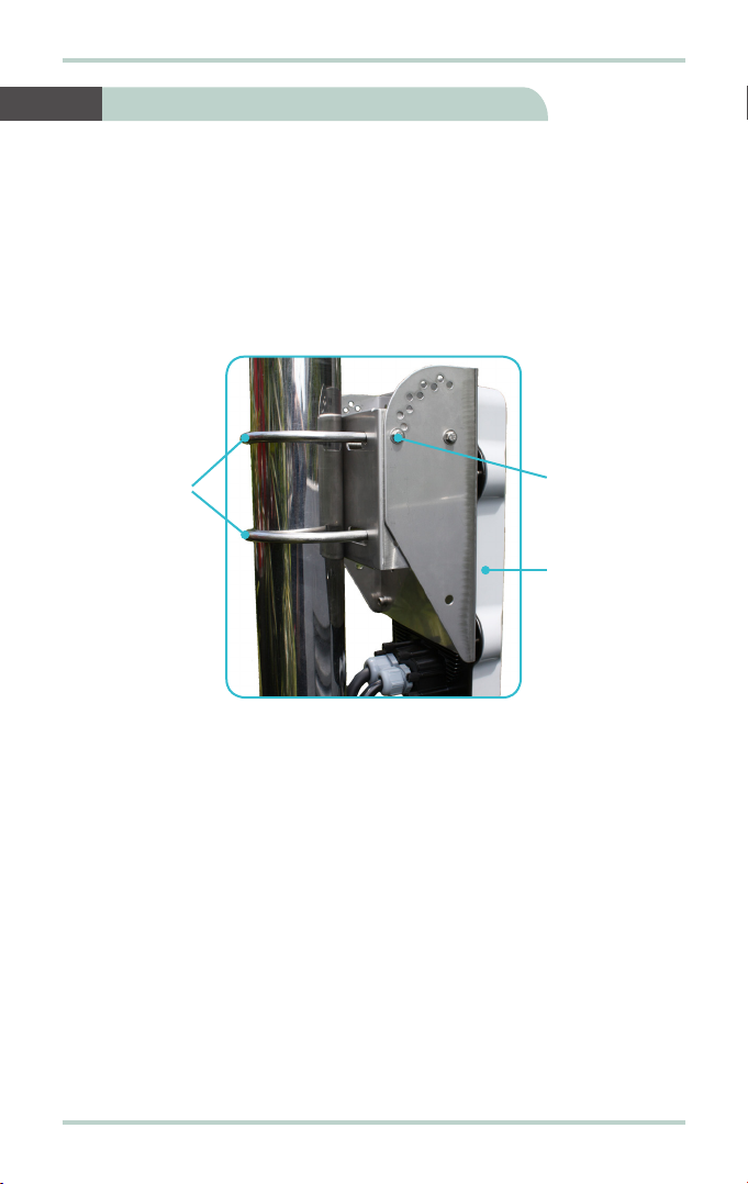
Follow these steps to mount the SABRETM Ranger terminal:
1. Locate a vertical pole or column to mount the SABRETM Ranger terminal.
2. Mount the SABRETM Ranger terminal to the vertical pole or column using
two U-bolts, four nuts and washers.
3. Tighten the four nuts evenly to secure the SABRETM Ranger terminal to the
vertical pole or column.
SABRETM
Ranger
terminal
Lock bolt for
elevation
Secure the
U-Bolt to
vertical pipe
or pole
6 Mounting the SABRETM Ranger
9
SABRETM Ranger Installation Guide
Follow these steps to position the SABRETM Ranger terminal:
1. Remove two lock bolts and nuts on either side of the mounting frame.
2. Adjust the elevation of the SABRETM Ranger terminal and secure its position
using the two lock bolts and nuts on either side of the mounting frame.
3. SecurethelengthoftheMulti-functionandHeaterpowercablestothepole
or column using cable ties.
Note:
Ensure there is some slack at both ends of the Multi-function and Heater power
cables to avoid any stress build-up, which may damage the cable glands.
7 Positioning the SABRETM Ranger
SABRETM Ranger Installation Guide
10
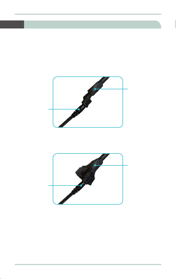
Follow these steps to power up the SABRETM Ranger (V1 variant) terminal:
1. Insertthepoweradapter outputplug intothe DCpowerinputsocketonthe
Multi-function cable.
2. Insert the plug end of the power adapter into an AC outlet.
3. Turn on the power to power up the SABRETM Ranger terminal.
8 Powering Up the SABRETM Ranger (V1 Variant)
Multi-function
cable
DC power
input cable
Ethernet
port
Phone
port DC power
input
socket
11
SABRETM Ranger Installation Guide
Note:
The following steps are applicable only if you are using the SABRE™ Ranger
(V2 variant) terminal:
Follow these steps to power up the SABRE™ Ranger (V2 variant):
1. Insert the power adapter output connector into the DC power input socket
on the Heater power cable.
2. Insert the plug end of the power adapter into an AC outlet.
3. Insert the power adapter output connector into the DC power input socket
on the Multi-function cable.
4. Insert the plug end of the power adapter into an AC outlet.
5. Turn on the power to power up the heater and SABRE™ Ranger terminal.
6. Allow 30 minutes for the heater to warm up the SABRE™ Ranger terminal.
7. Check to see if the SABRE™ Ranger terminal is working normally.
8. If the SABRE™ Ranger terminal is not working properly, proceed to power
cycle the terminal. After this process, the SABRE™ Ranger terminal should
be working normally.
Heater power
cable
DC power
input cable
9 Powering Up the SABRETM Ranger (V2 Variant)
Multi-function
cable
DC power
input cable
SABRETM Ranger Installation Guide
12
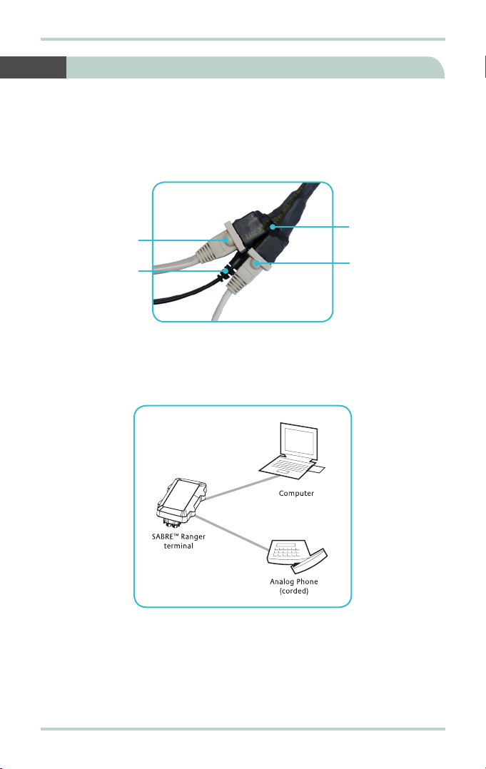
Follow these steps to connect the SABRETM Ranger terminal to your computer
using Ethernet:
1. Insert one connector end of the Ethernet cable to the Multi-function cable’s
Ethernet port.
2. Insert the other connector end of the Ethernet cable to your computer’s
Ethernet port.
A message confirming connection is displayed on your computer.
10 Connecting to your Computer via Ethernet
Phone cable
DC power
input cable
Ethernet
cable Multi-function
cable

13
SABRETM Ranger Installation Guide
The BGAN network requires valid GPS co-ordinates to successfully register your
SABRETM Ranger terminal for the first time or after you have performed a Factory
Reset. The terminal will perform the GPS acquisition automatically.
Follow these steps to obtain GPS co-ordinates:
1. Ensure that the SABRETM Ranger terminal is facing upwards and with an
open view of the sky.
2. Start your Internet browser.
3. Type http://192.168.1.35 in the Address field and press Enter.
The Connect to 192.168.1.35 login screen appears.
4. Typeinadmininthe Username field and wideye in the Passwordfield.Click
OK.
11 Obtaining GPS Co-ordinates


15
SABRETM Ranger Installation Guide
Establishing a connection with the BGAN network requires the careful
orientation of the SABRETM Ranger terminal towards the satellite, a process
called antenna pointing.
To perform antenna pointing, you will need a compass and the following
information from the Web Console:
• Pointing Angle (Azimuth and Elevation)
• Signal stength indicator bar
With the SABRE™ Ranger Web Console launched, follow these steps to register
with the network:
1. Select the satellite that you want the SABRETM Ranger terminal to point to.
2. Rotate the terminal left or right until it points in the correct horizontal
direction as indicated in the Azimuth reading with the aid of a compass.
3. Tilt the terminal slowly up or down until it points in the correct vertical
direction as indicated in the Elevation reading.
4. With the aid of the Signal indicator bar on the Web Console, fine tune the
pointing direction to obtain the maximum signal strength.
12 Registering with the BGAN Network

SABRETM Ranger Installation Guide
16
5. Secure the mounting after obtaining maximum signal strength.
Note:
For any service to commence, minimum 45dBHz signal strength is required.
6. Click Register Network to register to the BGAN network.
Once network registration is completed, the Registered to network. You
are now able to make phone call or send SMS and data transfer message
is displayed.
Note:
The GPS co-ordinates will not be displayed until you click Register Network
toregistertoInmarsat’sBGANnetwork.TheGPSdisplayprohibitedmessage
willbe displayediftheGPScoordinatesareprohibitedbytheBGAN network.

17
SABRETM Ranger Installation Guide
13 Making a Phone Call
Note:
This SABRETM Ranger terminal is not intended to be connected to any North
American (U.S., Canada) TNV circuit or PSTN (Public Switch Telephone Network).
Follow these steps to make phone calls:
1. Connect a corded analog phone to the Multi-function cable’s Phone port.
2. Dial the other party’s number using the following format:
00 <country code> <phone number> followed by #key.
SABRETM Ranger Installation Guide
18
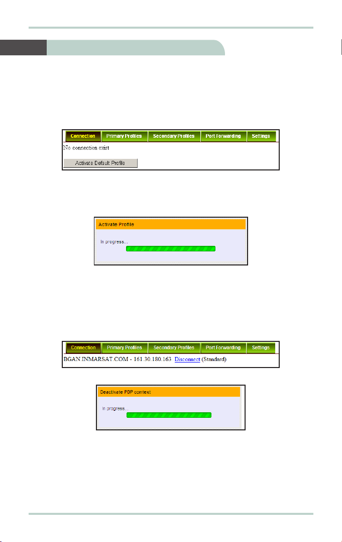
Follow these steps to activate the default profile:
1. Click Activate Default Profile.
The PDP context will be activated.
When connected, APN and IP Address details will be displayed.
You can proceed to use the Internet features.
Follow these steps to disconnect the data connection:
1. Click Disconnect.
The PDP context will be deactivated.
14 Activate PDP Connection

This manual suits for next models
2
Table of contents
Other Inmarsat Touch Terminal manuals


