manuals.online logo
Brands
  1. Home
  2. •
  3. Brands
  4. •
  5. Carel
  6. •
  7. Touch Terminal
  8. •
  9. Carel AX3000 Series User manual

Carel AX3000 Series User manual

+0500142EZ - rel. 1.0 - 03.07.2018
用户终端控制与远程显示装置MPXone / User terminal and remote display for MPXone
AX3000*
AX3000*小型终端连接到CAREL MPXone控制器时,用作集中商业
制冷应用软件的用户界面,其自带3位数字显示,显示数值范围
是:-999到999。通过NFC界面(近场通信)和BLE(低功耗蓝牙)
实现的无线连接,允许与采用安卓操作系统的移动设备(已安装
了CAREL“APPLICA”应用软件,安卓操作系统可以从Google Play中下
载(如需)此软件)进行交互作用。四键式键盘可允许用户修改
控制器设置。尺寸小、设计简单、与移动设备的可连接性均简化
了现场的参数配置和装置调试。更多信息,请参阅MPXone系统
手册+0300086EN,购买之前,可以在网站www.carel.com上的“文
件”中查阅。
初始操作
用户终端配备了框架,但可以在不影响IP防护等级的情况下轻松
拆除框架。
框架拆卸 步骤:在A点(图2)上,按住框架,轻轻向上
推,直到听到“咔哒”一声,然后在B点、C点、D
点上重复上述操作,直至拆下框架。
框架组装 反向重复拆除框架的操作。
在面板上安装用户终端
重要事项:仅满足以下条件时,才能保证前端的防护等级为
IP65:
• 矩形孔与平面的最大偏差:≤0.5毫米;
• 配电盘金属板的厚度:0.8-2毫米;
• 安装垫圈的表面最大粗糙度:≤120微米。
注意:用于制作配电盘的金属板(或材料)的厚度必须能够
确保终端安装的安全和牢固。
安装在面板上
前端
1. 将配电盘的电缆插入A点(图3);
2. 将电缆穿过电缆接头H;
3. 将控制器放置在开孔中,轻轻按住侧面配件,然后推动前端
直到完全插入为止(侧面接头会弯曲,搭扣会将控制器连接
到面板上)。
拆除
从后端打开配电盘(图4):
1. 按住配件,将控制器推出。
显示屏
用户终端 远程显示屏
3
1 2
2
1
图例 图例
1主域区 1主域区
2键盘 2操作模式
3操作模式
图标
图标 功能 开启 闪烁
电磁阀/压
缩机 电磁阀/压缩机启动 由计时器启动的压
缩机操作
蒸发器风扇 蒸发器风扇启动 -
照明灯 照明灯点亮 -
辅助输出 辅助输出启动 -
时钟 调度机启动 -
节能 Smooth Lines平滑线
启动 -
除霜 除霜启动 等待除霜
维修 维护请求
HACCP HACCP 启动 -
按键
向上 向下
• 增大/减小该值
• 滚动选择直接访问功能
• LED点亮:滚动选择菜单、参数、直接访问功
能
• LED闪烁:设置参数值
Prg
短按该键:
• 保存值,并返回参数代码
• 进入直接访问功能菜单(从主屏幕),并启
用/禁用功能
按住该键(3秒):
• 进入编程模式或返回上一级,但是不保存
• LED点亮:主屏幕/编程模式
Alarm
• 短按该健:显示屏报警
• 按住该键(3秒):重置报警
• LED点亮/闪烁:确认/启动报警
代码 型号 P/N Model
AX3000PS2002(0/1)(*)
用户终端:NFC连接,4
个按钮,蜂鸣器
AX3000PS2002(0/1)
(*)
User terminal, NFC conn., 4
buttons, buzzer
AX3000PS2003(0/1)
(*)
用户终端:NFC+BLE连
接,4个按钮,蜂鸣器
AX3000PS2003(0/1)
(*)
User terminal, NFC+BLE
conn., 4 buttons, buzzer
AX3000PS20X1(0/1)(*) 远程显示:不带键
盘,只读数据
AX3000PS20X1(0/1)(*) Remote display without
keypad, read-only data
(*)
(0/1): 单个包装/多个包装 (20 个装/包)
(*)
(0/1): single/multiple pack (20 pieces)
配件 /
Accessories
代码 型号 P/N Model
ACS00CB000020 用户接口电缆:1.5米ACS00CB000020 User interface cable, 1.5m
ACS00CB000010 用户接口电缆:3米ACS00CB000010 User interface cable, 3m
ACS00CB000022 用户接口电缆:1.5米,10
个装/包
ACS00CB000022 User interface cable, 1.5m,
multiple pack of 10
ACS00CB000012 用户接口电缆:3米,10
个装/包
ACS00CB000012 User interface cable, 3m,
multiple pack of 10
尺寸 /
Dimensions
- mm (in)
78.5 (3.1)
36.5
(1.4)
88.6 (3.5)
46.6
(1.8)
30 (1.2)
30 (1.2)
con cornice/
with frame
senza cornice/
without frame
dima di foratura
drilling template
71x29 mm
Fig. 1
框架拆卸/ Frame dismantling
A
D
B
C
Fig. 2
面板安装/ Panel mounting
1
A
H
2
3
Fig. 3
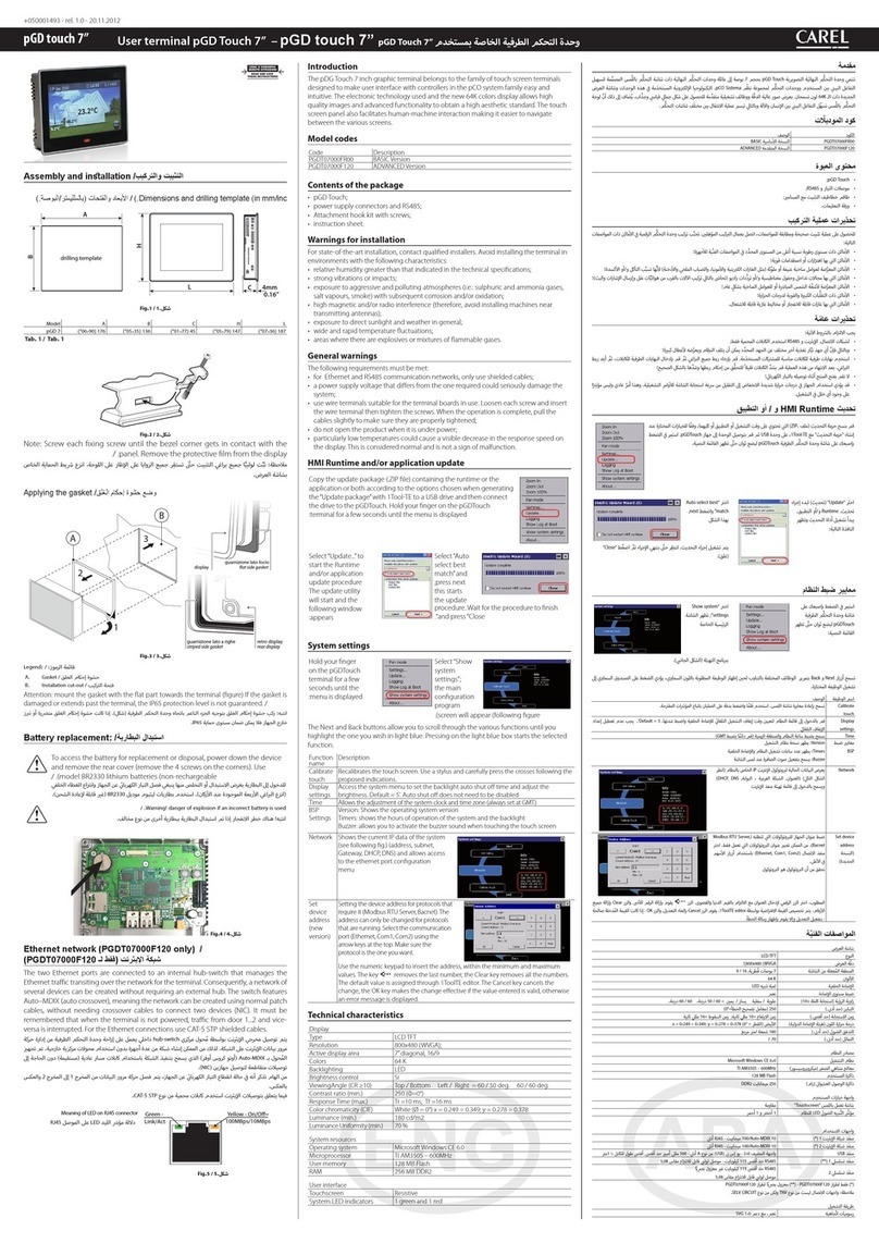
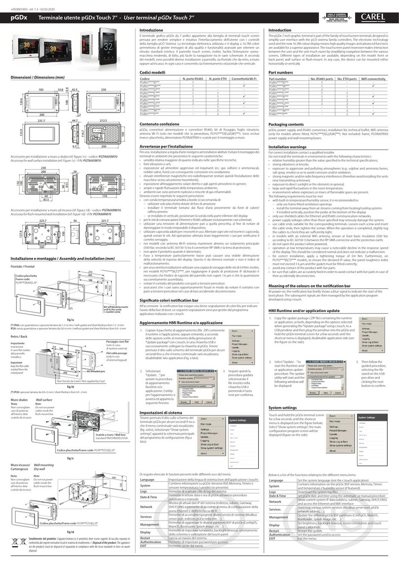
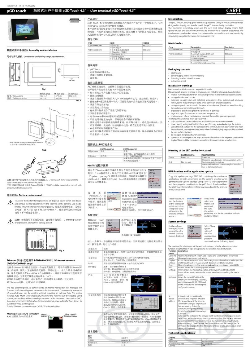
The AX3000* compact terminals, when connected to a CAREL MPXone
controller, are used as user interfaces for centralized commercial
refrigeration applications. They come with a three-digit display showing
values from -999 to 999.Wireless connectivity via the NFC interface (Near
Field Communication) e BLE (Bluetooth Low Energy), allows interaction
with mobile devices (after having installed the CAREL “APPLICA” app,
available on Google Play (on request) for the Android operating system).
The four-button keypad allows users to modify the controller settings.
Compact dimensions, simple design and connection to mobile devices
all simplify parameter conguration and unit commissioning in the eld.
For further information, see the MPXone system manual +0300086EN,
also available prior to purchase, on the www.carel.com website under
“Documentation”.
Preliminary operations
The user terminal is supplied with the frame already tted. Nonetheless,
this can be easily removed without aecting the IP protection rating.
Removing
the frame
Procedure: press the frame gently upwards at point A
(Fig.2) until hearing a click and repeat the operation at
the other points B, C, D so as to detach the frame
Assembling
the frame
Repeat the removal operations in reverse order
Mounting the terminal on the panel
Important: front IP65 protection is only guaranteed if the following
conditions are met:
• maximum deviation of the drilling rectangle from at: ≤ 0.5 mm;
• electrical panel sheet metal thickness: 0.8 - 2 mm;
• maximum roughness of the surface where the gasket is applied:
≤ 120 μm.
Note: the thickness of the sheet metal (or other material) used to make
the electrical panel must be suitable to ensure safe and stable installation of
the terminal.
Mounting on the panel
Front
1. insert the cable from the electrical panel into point A (Fig.3);
2. run the cable through the cable gland H;
3. place the controller in the opening, press lightly on the side tabs and
then on the front until fully inserted (the side tabs will bend, and the
catches will attach the controller to the panel).
Removal
Open the electrical panel and from the rear (Fig.4):
1. press on the mounting tabs and then push the controller out.
Displays
User terminal Remote display
3
1 2
2
1
Key Key
1 Main eld 1 Main eld
2 Keypad 2 Operating mode
3 Operating mode
Icons
Icona Function On Flashing
Solenoid/
compressor
Solenoid/compressor
active
Compressor
operationforced by
timers
Evaporator fan Evaporator fan on -
Lights Light on -
Auxiliary output Auxiliary output active -
Clock Scheduler active -
Energy saving Smooth Lines active -
Defrost Defrost active Awaiting defrost
Service Maintenance request
HACCP HACCP active -
Keypad
UP DOWN
• Increase/decrease value
• Scroll functions with direct access
• LED on: scroll menu, parameters, direct access
functions
• LED ashing: modify parameter values
Prg
Pressed briey:
• save value and return to parameter code
• enter direct access functions menu (from main
screen) and activate/deactivate functions
Pressed and held (3 s):
• enter programming mode or return to previous
level without saving
• LED on: standard display/programming mode
Alarm
• Pressed briey: display alarms
• Pressed and held (3s): reset alarms
• LED on/ashing: acknowledged/active alarm
NO POWER
& SIGNAL
CABLES
TOGETHER
READ CAREFULLY IN THE TEXT!
始终将信号电缆和电源电缆
放在不同导线管中。
警告
该产品将集成和/或整合到最终的仪器或设备中。制造商有责任验证最终的仪器或设备是否符
合其将投入运行的国家的现行法律和技术标准。产品交付之前,Carel已通过典型的测试设置
完成了相关欧洲指令和协调标准要求的检查和测试,但不得将所述测试设置视为已代表了一
切可能的最终安装条件。
WARNINGS
This product is to be integrated and/or incorporated into the nal apparatus or equipment. Verication of conformity to the laws and technical
standards in force in the country where the nal apparatus or equipment will be operated is the manufacturer’s responsibility. Before delivering the
product, Carel has already completed the checks and tests required by the relevant European directives and harmonised standards, using a typical
test setup, which however cannot be considered as representing all possible conditions of the nal installatio
n.
Always keep the signal cables
and power cable in separate conduits.
CAREL Industries HQs
Via dell’Industria, 11 - 35020 Brugine - Padova (Italy)
Tel. (+39) 0499716611 – Fax (+39) 0499716600 – www.carel.com – e-mail: carel@carel.com +0500142EZ - rel. 1.0 - 03.07.2018
CAREL保留在未事先通知的情况下对产品进行变更的权利。
CAREL reserves the right to modify its products without notice.
IMPORTANT WARNINGS
The CAREL product is a state-of-the-art product, whose operation is specied in the
technical documentation supplied with the product or can be downloaded, even prior to
purchase, from the website www.carel.com. - The client (builder, developer or installer
of the nal equipment) assumes every responsibility and risk relating to the phase of
conguration the product in order to reach the expected results in relation to the specic
nal installation and/or equipment. The lack of such phase of study, which is requested/
indicated in the user manual, can cause the nal product to malfunction of which CAREL can
not be held responsible. The nal client must use the product only in the manner described
in the documentation related to the product itself. The liability of CAREL in relation to its own
product is regulated by CAREL’s general contract conditions edited on the website www.
carel.com and/or by specic agreements with clients.
拆卸/ Dismantling
1
Fig. 4
更换 Replacing
如需更换用户终端,为避免发生故障:
1. 关掉该装置的电源;
2. 更换用户终端;
3. 重新启动装置。
In case of replacing the user terminal, to
avoid malfunctions:
1. switch o (unplug) the unit;
2. replace the user terminal;
3. restart the unit.
NFC/蓝牙通讯 NFC/BLE communication
近场通信(NFC)简单快速,可在与控
制器通信时使用。更多信息,请参阅
MPXone系统手册+0300086EN。
NFC (Near Field Communication) is
simple and fast and can be used when
commissioning the controller. For further
information, see the MPXone system
manual +0300086EN.
300086_028_R01
Fig. 5
(1)符合“微功率短距离无线电发射设备目录和技术要求”的具体条款和使用场
景,采用的天线类型和性能,控制、调整及开关等使用方法;
(2)不得擅自改变使用场景或使用条件、扩大发射频率范围、加大发射功率(包括
额外加装射频功率放大器),不得擅自更改发射天线;
(3)不得对其他合法的无线电台(站)产生有害干扰,也不得提出免受有害干扰保
护;
(4)应当承受辐射射频能量的工业、科学及医疗(ISM)应用设备的干扰或其他合
法的无线电台(站)干扰;
(5)如对其他合法的无线电台(站)产生有害干扰时,应立即停止使用,并采取措
施消除干扰后方可继续使用;
(6)在航空器内和依据法律法规、国家有关规定、标准划设的射电天文台、气象雷
达站、卫星地球站(含测控、测距、接收、导航站)等军
民用无线电台(站)、机场等的电磁环境保护区域内使用微功率设备,应当遵守电
磁环境保护及相关行业主管部门的规定;
(7)禁止在以机场跑道中心点为圆心、半径5000米的区域内使用各类模型遥控器;
(8)微功率设备使用时温度和电压的环境条件。
电气接线图 / Electrical connections
用户终端 User terminal
J8
J4 BMS
J3 J2
J5 FBus
S1 S3 5V
S2Y2
Y1ID1
ID2
ID3ID5
ID4S4
S6 +V
VL S5
to user terminal
ACS00CB0000** cable
远程显示 Remote display
GND
Rx+/Tx+
Power supply
Rx-/Tx-
J1J7
NO4CG0 G
J6
NO2 NO3
C
NO1
J2
J3
J4 BMSJ5 FBus
S1 S3 5V
S2Y2
Y1ID1
ID2
ID3ID5
ID4S4
S6 +V
VL S5
py
Fig. 6
报警表
当报警发生时,ALARM图标变为红色,用户终端显示相应报警代
码。
代码 说明
rE 控制探头
E1 S1探头故障
E2 S2探头故障
E3 S3探头故障
E4 S4探头故障
E5 S5探头故障
E6 S6探头故障
E11 S11串行探头未更新
E12 S12串行探头未更新
E13 S13串行探头未更新
E14 S14串行探头未更新
LO 低温
HI 高温
LO2 低温2
HI2 高温2
IA 外部触点瞬时报警
dA 外部触点延迟报警
dor 门开启过长
Etc 实时时钟未更新
LSH 低过热
LSA 低吸气温度
MOP 高蒸发温度
LOP 低蒸发温度
bLo 阀门阻塞
Edc 与步进驱动器的通讯误差
EFS 步进电机损坏/未接通
HA HA型HACCP报警
HF HF型HACCP报警
MA 与主机通信误差(仅在从机上)
u1...u9 与从机通信误差(仅在主机上)
n1...n9 网络中装置1... 9的报警
GPE 自定义气体参数误差
技术规范
电源 13 Vdc ± 10% ACU控制器电源;
最大电流 250 mA. 控制器连接推
荐电源:SELV或PELV
接头 (内置式) JST 4-针ZH P/N S4B-ZR-SM4A-TF
控制器连接电缆 最大长度:10米。B如果其长度
超过2米,且没有内置设备,那
么使用屏蔽电缆。
尺寸: AWG: 26
连接器:
• 终端侧:JSTZH 4条引线;
外壳:ZHR-4;终端 SZH-
002T-P0.5
• 控制侧:
–用户终端:JSTXH 4路,
外壳:XHP-4,终端 SXH-
002T-P0.6
–远程显示:线对线
蜂鸣器 所有机型均配备
温度传感器 内置
壳体 聚碳酸酯材料
尺寸:见图纸
组装 面板安装
显示 3位数字、小数点及多功能图标
操作温度 -20T60°C
操作湿度 <90%rH 无冷凝
储存温度 -35T70°C
储存湿度 <90%rH 无冷凝
NFC 最大距离:10毫米,可根据使用
的移动设备进行调整。
低功耗蓝牙 最大长度:10米,根据使用的移
动设备确定
防护等级 IP65 前端, IP20 后端
环境污染等级 3
球压试验 125°C
额定冲击电压 0.8 kV
启动和断开类型 1.Y
控制设备的结构 设备将进行整合
防电击等级 整合为1类或2类器械
串行接口 RS485以上的Modbus通讯协议
软件类和结构 A类
前端清洁 只能使用柔软、非研磨抹布和中
性洗涤剂或水
认证 CE, UL
电气安全:
EN60335-1, UL60335-1,
EN60730-1, UL60730-1
电磁兼容性:
EN61000-6, EN61000-3, EN55014-1,
EN61000-4, EAC
Alarm table
When an alarm occurs, the LED on the controller turns red and the user
terminal displays the code corresponding to the alarm
Code Description
rE Control probe
E1 Probe S1
E2 Probe S2
E3 Probe S3
E4 Probe S4
E5 Probe S5
E6 Probe S6
E11 Serial probe S11 not updated
E12 Serial probe S12 not updated
E13 Serial probe S13 not updated
E14 Serial probe S14 not updated
LO Low temperature
HI High temperature
LO2 Low temperature
HI2 High temperature
IA Immediate alarm from external contact
dA Delayed alarm from external contact
dor Door open for too long
Etc Real time clock not updated
LSH Low superheat
LSA Low suction temperature
MOP Max evaporation pressure
LOP Low evaporation pressure
bLo Valve blocked
Edc Communication error with stepper driver
EFS Stepper motor broken/not connected
HA HACCP type HA
HF HACCP type HF
MA Communication error with the Master (only on Slave)
u1...u9 Communication error with the Slave (only on Master)
n1...n9 Alarm on unit 1 ... 9 in the network
GPE Error in the custom gas parameters
Technical specications
Power supply 13 Vdc ± 10% supplied by ACU
controller; max current 250 mA.
Power supply recommended for the
connected controller: SELV or PELV
Connector (built-in) JST 4 pin ZH P/N S4B-ZR-SM4A-TF
Controller connection
cable
Max length: 10m. If of lengths longer
than 2m and device not uilt-in, use
shielded cable.
Size: AWG: 26
Connectors:
• terminal side: JST ZH 4 pin; housing
ZHR-4; terminal SZH-002T-P0.5
• control side:
– user terminal: JST XH 4 way,
housing XHP-4, terminal SXH-
002T-P0.6
– remote display: wires to wire
Buzzer Available on all models
Temperature sensor Built-in
Casing Polycarbonate material
Dimensions: see gures
Assembly Panel mounting
Display 3 digits, decimal point and
multifunction icons
Operating temperature -20T60°C
Operating humidity <90% RH non-condensing
Storage temperature -35T70°C
Storage humidity <90% RH non-condensing
NFC Max distance 10 mm, variable
according to the mobile device used
Bluetooth Low Energy Max length 10m, depend on the
used mobile device
Index protection IP65 at front,
IP20 at rear
Environmental pollution 3
Ball pressure test 125°C
Rated impulse voltage 0.8 kV
Type of action and disconnection 1.Y
Construction of the control
device
Device to be incorporated
Classication according to
protection against electric shock
To be incorporated in class 1 or 2
appliances
Serial interface Modbus over RS485
Software class and structure Class A
Cleaning the front side Only use a soft, non-abrasive cloth
and neutral detergents or water
Certications CE, UL
Electrical safety:
EN60335-1, UL60335-1,
EN60730-1, UL60730-1
Electromagnetic compatibility:
EN61000-6, EN61000-3, EN55014-1,
EN61000-4, EAC
Thecompleteusermanual (+0300086EN)forthe
product can be downloaded at www.carel.com
under the “Services / Documentation” section
or via QR Code.
Disposal of the product
The appliance (or the product) must be disposed of separately in
compliance with the local standards in force on waste disposal.
重要警告
CAREL始终致力于为您提供最先进的产品和服务,相关操作方法已在产品随附的技
术文档中加以说明,也可以在购买前从www.carel.com网站下载。客户(制造商、开
发商或最终设备的安装人员)承担与产品配置有关的所有责任和风险,旨在实现与
特定最终装置和/或设备有关的预期结果。如果未能完成用户手册中要求/指明的此
类操作,可能会导致最终产品出现故障;在这种情况下,CAREL不承担任何责任。
客户须按照与产品有关的文档中所述的方式使用本产品。CAREL的通用合同条款规
定了CAREL公司对其产品的责任,该条款可从www.CAREL.com网站和/或与客户达成
的特定协议中获得。
有关本产品的用户手册完整版(代码
+0300086EN)可从www.carel.com网站中
的“Services / Documentation”(“服务/文档”)
板块下载,或通过扫一扫左侧二维码获取。
产品的处置
根据当地现行的废物处置法规必须单独处置本设备(或本产品)
。
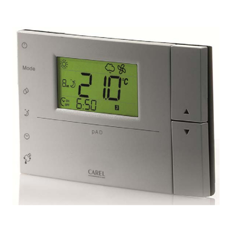
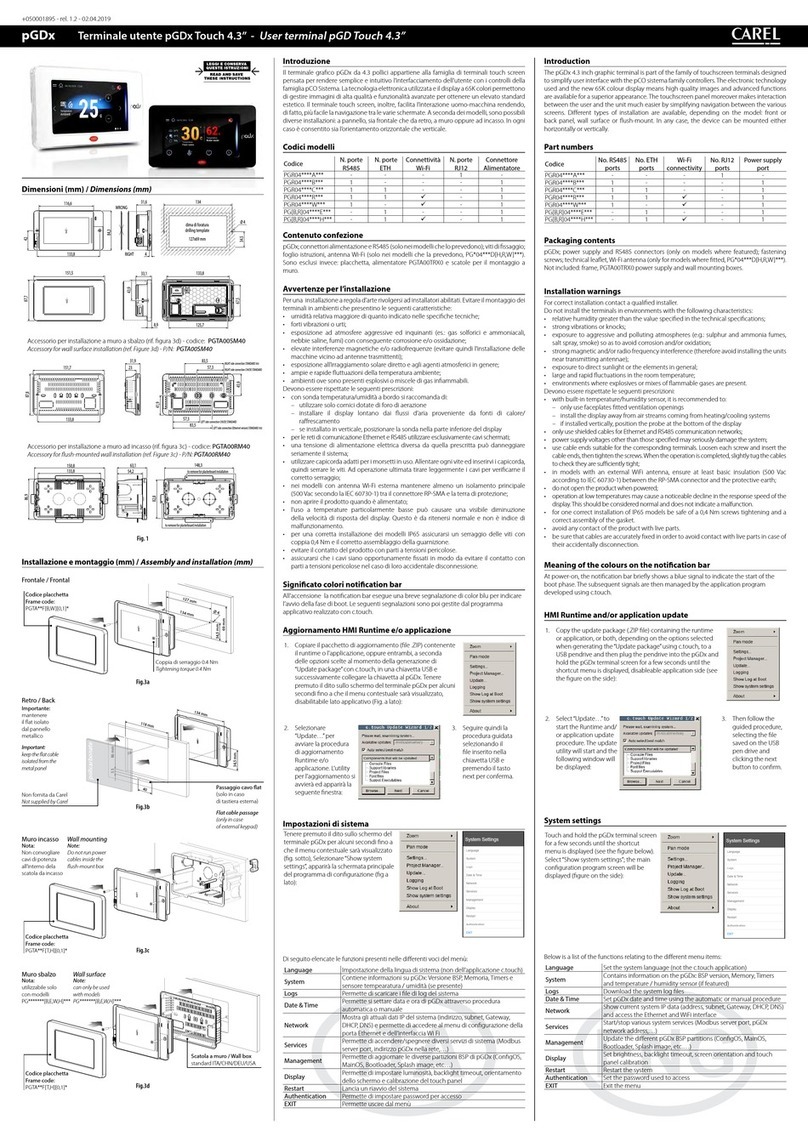
This manual suits for next models

3

Other Carel Touch Terminal manuals

Carel pGDx User manual

Carel

Carel pGDx User manual

Carel pGDx User manual

Carel

Carel pGDx User manual

Carel AX5000 User manual

Carel

Carel AX5000 User manual

Carel pGD touch Instruction Manual

Carel

Carel pGD touch Instruction Manual

Carel MTST User manual

Carel

Carel MTST User manual

Carel pGDx User manual

Carel

Carel pGDx User manual

Carel pGD Series User manual

Carel

Carel pGD Series User manual

Carel pGDx Series Instruction Manual

Carel

Carel pGDx Series Instruction Manual

Carel pGD 7 Series User manual

Carel

Carel pGD 7 Series User manual

Carel pGDx Touch 4.3” User manual

Carel

Carel pGDx Touch 4.3” User manual

Carel pGD Touch User manual

Carel

Carel pGD Touch User manual

Carel pGDx Touch 4.3 User manual

Carel

Carel pGDx Touch 4.3 User manual

Carel TH Tune User manual

Carel

Carel TH Tune User manual

Carel pGD Touch Instruction Manual

Carel

Carel pGD Touch Instruction Manual

Carel pGD Series User manual

Carel

Carel pGD Series User manual

Carel pGD touch PGDT04000FS00 Instruction Manual

Carel

Carel pGD touch PGDT04000FS00 Instruction Manual

Carel EasySet HYPW User manual

Carel

Carel EasySet HYPW User manual

Carel pGD Series User manual

Carel

Carel pGD Series User manual

Carel PLD Series User manual

Carel

Carel PLD Series User manual

Carel IR U Series User manual

Carel

Carel IR U Series User manual

Carel PAD User manual

Carel

Carel PAD User manual

Carel PAD User manual

Carel

Carel PAD User manual

Carel pGD Series User manual

Carel

Carel pGD Series User manual

Carel pGD touch 7 User manual

Carel

Carel pGD touch 7 User manual

Popular Touch Terminal manuals by other brands

Symbol VRC 6940 Product reference guide

Symbol

Symbol VRC 6940 Product reference guide

ZK Technology iFace 302 Series user guide

ZK Technology

ZK Technology iFace 302 Series user guide

Equitrac PageCounter Field service manual

Equitrac

Equitrac PageCounter Field service manual

Datecs Zettle user guide

Datecs

Datecs Zettle user guide

Datalogic F734-E Series user manual

Datalogic

Datalogic F734-E Series user manual

POSIFLEX TX-5600 user manual

POSIFLEX

POSIFLEX TX-5600 user manual

POSIFLEX Jiva LT-5600 user manual

POSIFLEX

POSIFLEX Jiva LT-5600 user manual

Teltonika FMC640 First start-up quick start guide

Teltonika

Teltonika FMC640 First start-up quick start guide

iMin D1 Installation and User Manual, Safety Instructions and Warning Booklet

iMin

iMin D1 Installation and User Manual, Safety Instructions and Warning Booklet

FlyTech POS455 user manual

FlyTech

FlyTech POS455 user manual

Elavon Verifone Evolution Series Quick reference guide

Elavon

Elavon Verifone Evolution Series Quick reference guide

3M 4588V-QCS Series instructions

3M

3M 4588V-QCS Series instructions

LAUNCH TECH HTT user manual

LAUNCH TECH

LAUNCH TECH HTT user manual

Elproma RB865io user manual

Elproma

Elproma RB865io user manual

Festo CPV10-GE-ASI-4E3A-Z M8 Brief description

Festo

Festo CPV10-GE-ASI-4E3A-Z M8 Brief description

Festo VIFB11 Series Brief description

Festo

Festo VIFB11 Series Brief description

HP Rp3000 - Point of Sale System Getting started guide

HP

HP Rp3000 - Point of Sale System Getting started guide

Worth Data RF Terminal 7000 owner's manual

Worth Data

Worth Data RF Terminal 7000 owner's manual

manuals.online logo
manuals.online logoBrands
  • About & Mission
  • Contact us
  • Privacy Policy
  • Terms and Conditions

Copyright 2025 Manuals.Online. All Rights Reserved.