manuals.online logo
Brands
  1. Home
  2. •
  3. Brands
  4. •
  5. InMotion
  6. •
  7. Security Camera
  8. •
  9. InMotion in30S1x1L User manual

InMotion in30S1x1L User manual

in30S1x1L Rev2
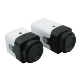
WDR ATM Camera
Quick Start Guide
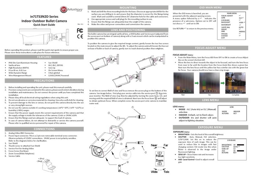
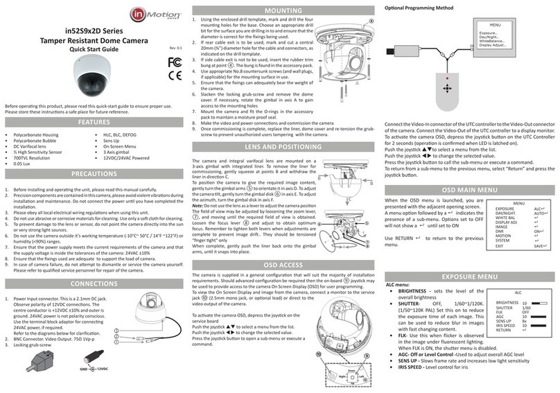
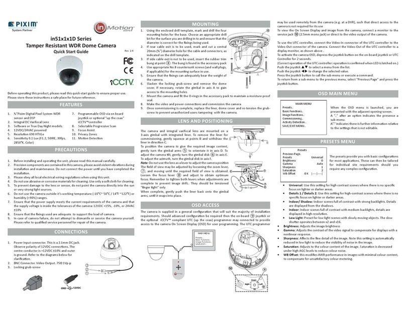
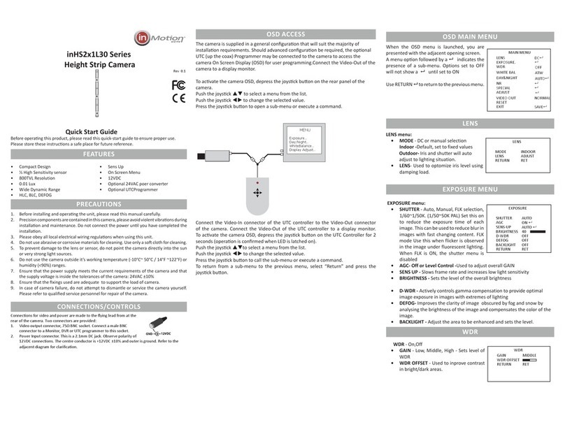
Before operang this product, please read this quick-start guide to ensure proper use. Please
store these instrucons in a safe place for future reference.
FEATURES
• ⅓”Pixim Digital Pixel System WDR
sensor and DSP
• Resoluon 690 HTVLe & pre-focussed
High Resoluon Lens
• Sensivity <0.28 Lux (F2.0, 50IRE, 30fps,
2850°K. Colour), 0.001Lux DSS on.
• Programmable OSD via oponal “up the
coax” iCCTVTM compliant controller
• Selectable Progressive Scan
• Mulple mounng bracket conguraon
PRECAUTIONS
1. Before installing and operang the unit, please read this manual carefully.
2. Precision components are contained in this camera, please avoid violent vibraons during
installaon and maintenance. Do not connect the power unl you have completed the
installaon.
3. Please obey all local electrical wiring regulaons when using this unit.
4. Do not use abrasive or corrosive materials for cleaning. Use only a so cloth for cleaning.
5. To prevent damage to the lens or sensor, do not point the camera directly into the sun
or very strong light sources.
6. Do not use the camera outside it’s working temperature (-10°C~ 50°C / 14°F ~122°F) or
humidity (<90%) ranges.
7. Ensure that the power supply meets the current requirements of the camera and that
the supply voltage is inside the tolerances of the camera: 12VDC±10%
8. Ensure that the xings used are adequate to support the load of camera.
9. In case of camera failure, do not aempt to dismantle or service the camera yourself.
Please refer to qualied service personnel for repair of the camera.
CONNECTIONS/CONTROLS
Connecons for video and power are made to the ying lead from at the rear of the
camera. Two connectors are provided:
1. Video output connector, 75Ω BNC socket. Connect a male BNC connector to a Monitor,
DVR or UTC programmer to this socket.
2. Power Input connector. This is a 2.1mm DC jack. Observe polarity of
12VDC connecons. The centre conductor is +12VDC ±10% and outer is
ground. Refer to the adjacent diagram for claricaon.
3. To enable the connecon to bare ended power cables, an oponal
adaptor is available. Observe polarity of DC connecons when using the
adaptor as mis-connecon of power may damage the unit. Such damage is
not covered under warranty Refer to the adjacent diagrams
4. Once connecons are complete, secure the video/power ying lead to
the camera bracket with the supplied cable e, to prevent accidental
disconnecon of the ying lead from the rear of the camera.
12VDC
GND
MOUNTING
The camera comes with a number of bracket opons, to enable the camera to be mounted
and posioned in restricted spaces. The brackets can be assembled in dierent combinaons,
with dierent pivot posions, to allow versale installaon.
The kits of parts includes:
1x Short U-Bracket ①
1x Long U-Bracket ②
2x Extension Arms ③
4x M2 Knurled lock screws ④
4x M2 Domed lock screws ⑤
4x M2 Flat pivot screws ⑥
1x cable tie
The dierent bracket conguraons are shown below:
Depending on the available installaon space, the knurled lock screws ④ may be interchanged
with the spare domed lock screws ⑤. The two combinations are shown in the illustrations.
Do not overtighten the lock screws. Remember to secure the power/video lead to the bracket
with the cable e as detailed in the previous secon.
OSD ACCESS
The camera is supplied in a general conguraon that will suit the majority of installaon
requirements. Should advanced conguraon be required then the oponal iCCTV™ compliant
UTC (up the coax) Programmer may connected to provide access to the camera On Screen
Display (OSD) for user programming. The UTC programmer may be used remotely from the
camera (e.g. at a DVR), such that direct access to the camera is not required for its use
MAIN MENU
Presets..
Basic Functions..
Image Functions..
SAVE/EXIT..
To view the On Screen Display, connect the Video-In connector of a UTC controller to the
Video-Out connector of the camera. Connect the Video-Out of the UTC controller to a display
monitor, as shown above .
To acvate the camera OSD, depress the joysck buon on the UTC Controller for 2 seconds.
(Correct operaon of the UTC controller: operaon is conrmed when LED is latched on.)
Push the joysck  to select a menu from the list.
Push the joysck  to change the selected value.
Press the joysck buon to call the sub-menu or execute a command.
To return from a sub-menu to the previous menu, select “Previous Page” and press the joysck
buon.
②
⑥
④
②
⑥④
③
⑥ ⑤
①
⑥
④
①
⑥④
③
⑥ ⑤
OSD MAIN MENU
When the OSD menu is launched, you are
presented with the adjacent opening screen.
A “..” aer an opon indicates the presence a
sub-menu.
A”.” indicates there is further informaon relave
to the sengs that is not editable.
PRESETS MENU
The presets provide you with basic conguraons
for most applicaons. These can then be tailored
for individual site requirements should you
require any complex conguraon.
• Universal: Use this seng for high contrast scenes where there is no specic
focus on lighter or darker areas.
• Details 1 / Details 2: Use this seng for high-contrast scenes where there is no
specic focus on lighter or darker areas.
• Indoor/ Shadow: Indoor scenes full of contrast with strong backlights. Details
are displayed from the shadows.
• Indoor: Indoor scenes full of contrast with medium backlights, details are
displayed in high resoluon.
• Low Light: Preset for low light scenes with slowly moving objects. The slow
shuer operates between x2 and x16.
• Brightness: Adjusts the image brightness
• Gamma: Adjusts the contrast of the video signal to compensate for displays with a
nonlinear response.
• Sharpness: Aects the ne detail of the image. Note this seng is automacally
reduced in low light to reduce the visibility of noise in the image.
• Saturaon: Adjusts to the colour content of the image. Saturaon is decreased
under high AGC levels to reduce colour noise.
• WBOset:this modies AWB performance in images with minimal colour content,
to compensate for unsasfactory colour metering.
BASIC FUNCTIONS MENU
• Day/Night Setup:
• Night control: Auto, selects Night mode in low
light; Color, disables night mode; Mono, forces
night mode, External selects control by the Lamp
Trigger input.
Auto Setup sub-menu - sets the transion points
for Day/Switching when auto is selected.
• Night Mode: Denes if burst is present in mono
• Night Max Gain: Denes Max AGC gain in mono
• Fluorescent: O, CRR reduces color roll under uorescent lighng
• Horizontal Flip: Mirror the image horizontally
• Video Level: Sets the video output level. This is factory set and should not need
MAIN MENU
Presets..
Basic Funcons..
Image Funcons..
Commissioning..
Acvity Detecon..
SAVE/EXIT MENU..
Presets
Previous Page.
Presets Universal
Brightness 0
Gamma Auto
Sharpness 1
Saturaon 2
WB Oset 0 K |----|----|
Basic Funcons
>Previous Page.
Day/Night Setup..
Fluorescent O
Horizontal Flip O
Video Level 100└┴⌂┴┴┴┘
CCTV System PAL..
Language English
Day / Night Setup
Previous Page.
>Night Control DC
Night Mode B/W + Burst
Night Max Gain 32
Rev 2.4
adjustment.
• CCTV System: Changes the TV Standard. Default is set according to shipping region
• Language: Opons are English & Spanish. The defaults are set by the shipping
region.
IMAGE FUNCTIONS MENU
• Progressive Scan: O, image is captured at eld rate, successive captures are used
for A and B elds. On, image is captured at 2x eld rate and eld A and B are gen-
erated from a single capture. Note: Camera must be rebooted to change between
scan modes.
• Backlight: On, camera is congured to reduce sil-
houeng eects of strong backlighng of a subject.
In this mode the camera behaves more like a CCD
camera.
• Digital Zoom: Default is o. Set to on and Digital
Zoom Sub-Menu is available when joysck is de-
pressed.
• Zoom: up to 4x zoom is available
• Pan & Tilt: When Zoom >1 it is possible to pan and lt around the image. 0 indi-
cates the central point of the image.
Note: Enabling zoom will disable Backlight feature.
• White Balance: Congures the operaonal white balance mode of the camera.
• ATW (default): Auto Tracking White Balance - camera automacally adjusts for
correct white balance.
• Push AWB: Use this to x white balance in
dicult lighng condions, hold a white card in
front of the camera, with light falling on it and
press the joysck to x the white balance.
• Manual: Use this to manually x the white
balance. Seng is given in °Kelvin and the range is
adjustable between 2000°K and 11000°K
COMMISSIONING MENU
• Camera ID: Assign a name to the camera, maximum 8 characters. Press joysck for
character entry.  Selects character. Press joystick to accept and move to next
character.  Escapes back to menu.
• ID Display: Sets tle display On or O
• Posion: Selects one of 6 preset posions for camera tle. Upper screen le,
centre or right, lower screen, le, centre or right.
• Privacy Masking: O, On, enables up to 12 Privacy
masks to obscure areas of the image. Turning a
zone on reveals its conguraon screen. Press the
joysck to cycle through the zone opons. A white
border indicates movement of the zone, green
increase size & red reduce size. Use to
move/re-size. A long press of the joystick closes
Image Funcons
>Previous Page.
Progressive Scan O
Backlight On
Digital Zoom O
White Balance ATW..
Digital Zoom
Previous Page.
>Zoom 1└⌂┴┴┴┴┴┴┴┴┘
Pan 0└┴┴┴┴⌂┴┴┴┴┘
Tilt 0└┴┴┴┴⌂┴┴┴┴┘
PUSH AWB Conrm
>Save AWB & All Changes.
Cancel.
*** WARNING ***
All user properties will
be written to flash
Commissioning
>Previous Page.
Camera ID..
Privacy Masking O
Mask Colour Black
Enable Masks 1~6
Previous Page.
>Mask 1 On..
Mask 2 O
Mask 3 O
Mask 4 O
Mask 5 O
Mask 6 O
Next Page
configuration.
• Mask Color: Black, White Red, sets the color of any enabled privacy masks
.
ACTIVITY MENU
• Alarm: Enabling acvity detecon displays an on screen
indicaon when moon is detected in any of the 4
zones.
• On: Enables acvity detecon. Pressing the joysck
reveals the acvity threshold, and adjusts the overall
sensivity.
• Setup Alarm Zone: Set Acve Zones enables the
individual acve alarm zones. Adjust Zone congures
the size & posion of each zone. The same method
is used to congure the size and posion of the Acvity Zones as Privacy Masking
Zones.
SAVE / EXIT MENU
• Save/RejectSengs&Exit:Reject or Save any changes made to the menus since the
last Save. **Note** Be sure to select Save to ensure any changes made are wrien to
the ash memory, other wise the sengs will not loaded on the next reboot of the
camera.
• LoadFactorySengs: Restores all menu sengs to the factory defaults
• Reset: Performs a soware reset (reboot) of the camera
• Menu / Firmware Version: Shows the rmware versions of the camera.
BRACKET DIMENSIONS
74mm
43mm
48mm
53mm
58mm
63mm
46mm
36mm
38mm
27mm
Acvity Detecon
>Previous Page.
Alarm On..
Setup Alarm Zone..
Alarm Zone Setup
Previous Page.
>Set Acve Zones 1 Zone
2 Zones
3 Zones
4 Zones
Adjust Zone 1
Adjust Zone 2
Adjust Zone 3
Adjust Zone 4
Save / Exit Menu
>Previous Page.
Save Sengs & Exit
Reject Sengs & Exit
Load Factory Sengs No.
Reset Camera
Firmware Revision 1.x - x
Menu Version 7.x-7.0x 0
SPECIFICATIONS
Image Sensor ⅓” DPS M8800
Signal System PAL / NTSC
Eecve Pixels 758 x 540 pixels
Resoluon 690 HTVLe
Min. Illuminaon (Sensor) 0.1Lux (F1.2, 50IRE, 30fps, 2850°K, Colour)
S/N Rao 50dB
White Balance Auto, 2000°K~11000°K
Dynamic Range 120dB Max, 101dB Typical
Electronic Shuer 1/50 ~ 1/100000 PAL (1/60 ~ 1/100000 NTSC)
Fast Shuer Normal, 1/100, 1/200 sec
Video Output 1.0V p-p, 75Ω
Power Supply 12VDC ±10%
Power Consumpon 1.7W
Dimensions (mm) 36H x 36W x 32D
Weight 80g
Operang Temp -10°C~50°C
Operang Humidity 90% non-condensing
Order ID PAL NTSC
2.5mm in30S1P1L25 in30S1N1L25
2.9mm in30S1P1L29 in30S1N1L29
3.8mm in30S1P1L38 in30S1N1L38
SUPPORT
North America:
inMoon CCTV Inc. USA
+1 214 960 4640
support-US@inmooncctv.com
Europe:
inMoon CCTV UK Ltd
+44 1782 366080
support-EU@inmooncctv.com
http://www.inmotioncctv.com

Other InMotion Security Camera manuals

InMotion in51TS2x2D Series User manual

InMotion

InMotion in51TS2x2D Series User manual

InMotion in45S3 2 Series User manual

InMotion

InMotion in45S3 2 Series User manual

InMotion in52TS3N2D Series User manual

InMotion

InMotion in52TS3N2D Series User manual

InMotion in52S9x2D Series User manual

InMotion

InMotion in52S9x2D Series User manual

InMotion in21 Series User manual

InMotion

InMotion in21 Series User manual

InMotion in10S1P1L User manual

InMotion

InMotion in10S1P1L User manual

InMotion in51S1P1D28V11 User manual

InMotion

InMotion in51S1P1D28V11 User manual

InMotion inHS2 1L30 Series User manual

InMotion

InMotion inHS2 1L30 Series User manual

InMotion in51S9P2D28V12 User manual

InMotion

InMotion in51S9P2D28V12 User manual

InMotion in71TS3N2D Series User manual

InMotion

InMotion in71TS3N2D Series User manual

InMotion in10S2x2L User manual

InMotion

InMotion in10S2x2L User manual

InMotion inTC Series User manual

InMotion

InMotion inTC Series User manual

InMotion in51S2x2D Series User manual

InMotion

InMotion in51S2x2D Series User manual

InMotion in60x1x1D Series User manual

InMotion

InMotion in60x1x1D Series User manual

InMotion in52S8x2D Series User manual

InMotion

InMotion in52S8x2D Series User manual

InMotion in30S1P1L25 User manual

InMotion

InMotion in30S1P1L25 User manual

InMotion in10S4x2L User manual

InMotion

InMotion in10S4x2L User manual

InMotion in10S3P2L User manual

InMotion

InMotion in10S3P2L User manual

InMotion in51x1x1D Series User manual

InMotion

InMotion in51x1x1D Series User manual

InMotion in51S3P2D28V22 User manual

InMotion

InMotion in51S3P2D28V22 User manual

InMotion in4 S1P1L Series User manual

InMotion

InMotion in4 S1P1L Series User manual

Popular Security Camera manuals by other brands

TRENDnet TV-IP300 Specifications

TRENDnet

TRENDnet TV-IP300 Specifications

Pulsar S108-CR quick start guide

Pulsar

Pulsar S108-CR quick start guide

Speco O8B7M quick start guide

Speco

Speco O8B7M quick start guide

Monacor TVCCD-25IR quick guide

Monacor

Monacor TVCCD-25IR quick guide

TRASSIR TR-D2251WDIR4 quick start guide

TRASSIR

TRASSIR TR-D2251WDIR4 quick start guide

Novus NVIP-5DN3613AH/IR-1P/F Short user manual

Novus

Novus NVIP-5DN3613AH/IR-1P/F Short user manual

IMOU Floodlight Cam quick start guide

IMOU

IMOU Floodlight Cam quick start guide

Bosch Junior Quick manual

Bosch

Bosch Junior Quick manual

LG LNV7210 owner's manual

LG

LG LNV7210 owner's manual

Bosch KBE-335V28-20 instruction manual

Bosch

Bosch KBE-335V28-20 instruction manual

Avigilon H5 installation guide

Avigilon

Avigilon H5 installation guide

Idis Direct IP DC-D Series installation manual

Idis

Idis Direct IP DC-D Series installation manual

Brickcom Vandal Dome V2 Series user manual

Brickcom

Brickcom Vandal Dome V2 Series user manual

Burg Wächter BWFC-261KDIA Quick installation guide

Burg Wächter

Burg Wächter BWFC-261KDIA Quick installation guide

Arlo Pro 4 Setup

Arlo

Arlo Pro 4 Setup

Dahua Technology DH-IPC-PFW83242-A180-S2 quick start guide

Dahua Technology

Dahua Technology DH-IPC-PFW83242-A180-S2 quick start guide

Moog PDW7CS-9 user guide

Moog

Moog PDW7CS-9 user guide

Lanpro LP-355IR installation guide

Lanpro

Lanpro LP-355IR installation guide

manuals.online logo
manuals.online logoBrands
  • About & Mission
  • Contact us
  • Privacy Policy
  • Terms and Conditions

Copyright 2025 Manuals.Online. All Rights Reserved.